For those of you who don't know, Dolton Junction is North America's largest operating mechanical lever frame interlocking tower located about 15 miles south of downtown Chicago. Over a couple of years while traveling on Amtrak Train 50, "The Cardinal" I have had opportunity to photograph the tower and parts of the interlocking and I seeing the ongoing series on Chicago area towers I feel its a good idea to share them here.
The massive complex that is Dolton Junction was created by the intersection of 4 railroad main lines. The Chicago and Western Indiana railroad ran north to Dearborn St Station as a terminal line that concentrated traffic from a number of other railroads, most notably the Chicago and Eastern Illinois, which eventually wound up owned by Union Pacific. Splitting the C&WI were the parallel east-west main lines of the Indiana Harbor Belt and the Baltimore and Ohio, Chicago Terminal railroads. Finally, playing the spoiler and crossing all the of the other main lines at an angle was the Pennsylvania Railroad's "Panhandle Route" main line from Columbus Ohio. Because the PRR was involved you can find an interlocking diagram here.
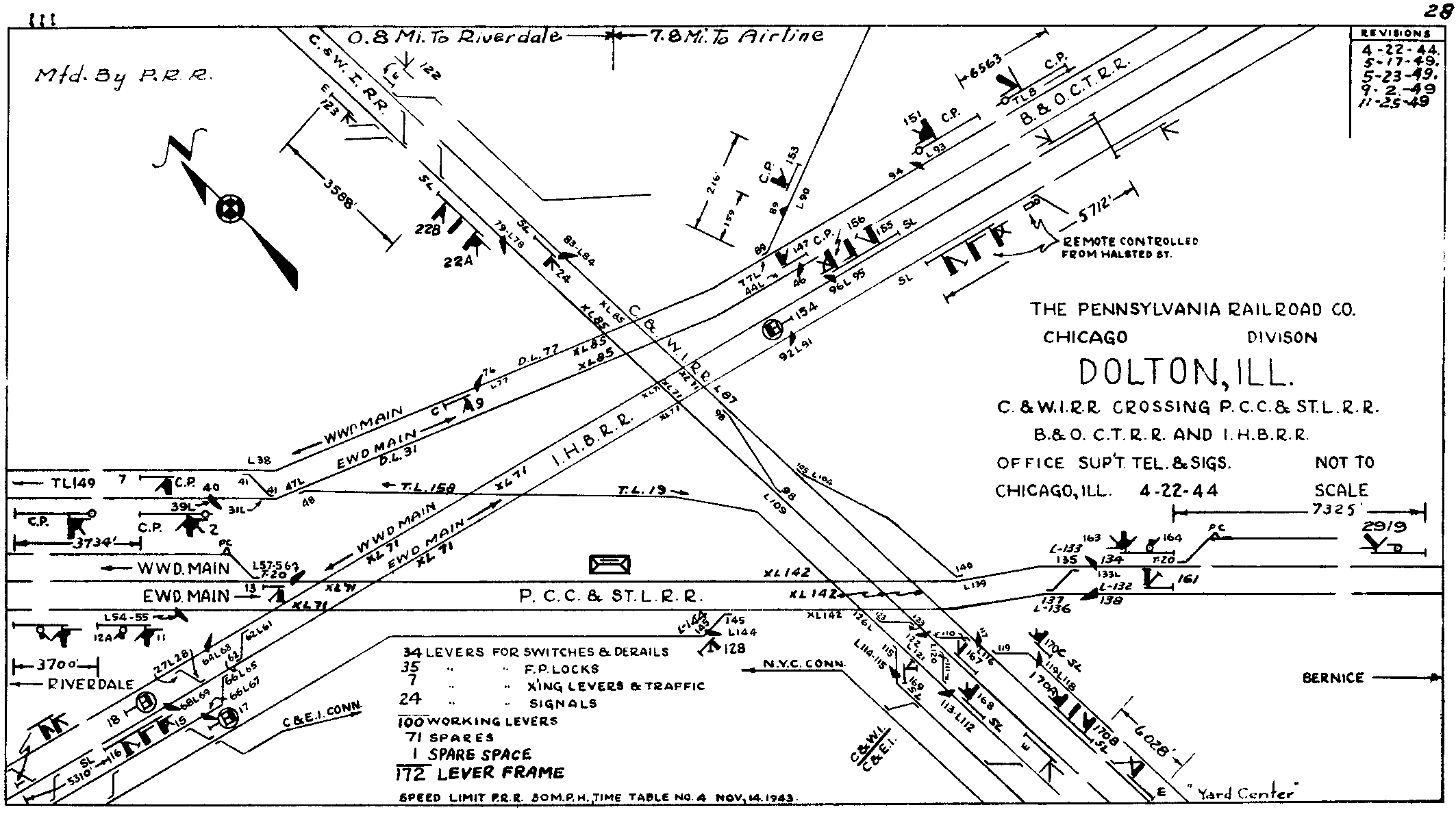
The tower at Dolton Junction was built in 1897 and contained a 178 lever frame with 100 active levers. As built the interlocking contained a total of 20 diamonds which included an extra 4 from various connection tracks between the main lines. At the time most of the routes through the plant were fitted with split point derails to prevent any catastrophic Stop signal violations.
Today the interlocking plant has seen some expensive reconfigurations carried out on the old mechanical frame. With the removal of the PRR route the number of diamonds has been reduced to 11 and a few new crossovers and connector tracks have been installed. Still the interlocking is operated as an island of manual control with CTC on all sides. Most of my photos were taken from the rear of a south/eastbound train as it passed through the interlocking in 2009.
Entering Dolton Junction from the North we pass the southbound home signal which is back to back with the signals for an independent interlocking that connects the C&WI line with the B&OCT line. The Doton signals stand out as they are older searchlights and not Darth Vaders.
Next we cross the B&OCT diamonds.
Then the IHB diamonds.
And now the tower itself. I believe you can just make out some of the levers inside the open window.
Another angle....
A blog devoted to explaining the ins and outs of North American railroad signaling, past, present and future. This blog seeks to preserve through photo documentation the great diversity and technical ingenuity of 20th century signaling and interlocking hardware and technology. Related topics cover interlocking towers and railroad communications infrastructure.
Note, due to a web hosting failure some of the photos and links may be unavailable.
Saturday, February 23, 2013
Monday, February 18, 2013
CORK Tower Closes: 1929-2013
At 10am on Tuesday February 19th, 2013 Amtrak's CORK Tower in Lancaster, PA will was planned to close for good and when it does finally close that will also drop the curtain on the last fully paper dispatched railroad main line in North America (although the LIRR probably still has some branch lines that can qualify as paper dispatched). CORK tower was opened in 1929 as the PRR re-routed its Main Line around downtown Lancaster (resulting in the infamous 1000 foot mile) and along with a shiny new station building the entire area was signaled by a new brick interlocking and an 67 lever US&S Model 14 interlocking machine. From end to end the whole interlocking was 3.2 miles long and controlled a junction of the Main Line with the Columbia Branch to COLA, the Reading Lititz Branch crossing both the Main Line and Columbia Branches, the Lancaster terminal area, the junction of the PRR New Holland Branch and, until 1948, the 4 track to 2 track squeeze on the main line at the Conestoga River Bridge.
CORK did not go quietly and was probably one of the most protracted interlocking resignalings of all time. The process started way back in 2005 (!) when the interlocking was dramatically reconfigured from its PRR vintage layout with the old station tracks being removed and the disused main tracks (previously used by freight trains that did not like high level platforms) being physically moved over to serve the platforms. The pneumatic point machines were replaced with electrics, new crossovers were added (but not activated) and many of the old freight sidings were reconfigured and a new freight bypass track installed. In 2008, with Rule 562 operation on its way east from Harrisburg, the old junction with the Lititz Branch was spun off as its own LITITZ interlocking, and about a year later the old Model 14 machine was finally retired with the remainder of CORK's territory being split into a new CORK interlocking west of the Station, CONESTOGA interlocking east of it and HOLLAND interlocking at the New Holland branch junction.
CORK was not about to have a little thing like re-signaling stop it as it simply exchanged its Model 14 for a bunch of panel machines controlling not only LITITZ, CORK, CONESTOGA and HOLLAND, but also the new interlocking at LEAMAN (formerly a TBS) and PARK (replacing the old PARK tower). CORK soldiered on with a 24/7 operator looking at the little portrait on the model board for three more years until Amtrak finally managed to move its NEC Mid-Atlantic dispatching facility from 30th St Station to Wilmington, DE in the fall of 2012. While the Section B and C dispatchers made the move with their large paper block registers, their new digs were fully equipped for computers and other modern amenities unlike the "back room" on the 8th floor of 30th St. With CORK's territory already under remote control it was simply a matter of adjusting the Wide Area Network to send the work out of State.
While it was inevitable that the Harrisburg Line would wind up as traditional CTC, the sad part is that both is and the southern NEC are no longer dispatched from a purpose built railroad structure. While Amtrak's new operations center in Wilmington is next to the NEC, it is not in a station or other PRR related building. The real irony is that the state of Pennsylvania has spent hundreds of millions of dollars to allow Amtrak to offshore about 10 or so jobs to Delaware while former dispatching offices in the Harrisburg Station not sit empty. Oh well, perhaps one day CORK and the other preserved towers will see new life as museums, or maybe not.
UPDATE: Due to unspecified issues the cutover was not successful and CORK remains in operation as of 2/22/13.
Saturday, February 9, 2013
PHOTOS: CPL Recycling at Landenburg Junction
Once upon a time in North America railroads were either seriously strapped for cash or railroad signaling hardware was abnormally expensive, but unlike today where re-signaling means installing 100% new signaling equipment and throwing out the old as recently as the 1990's it was common practice to reuse as much of the exigent hardware as possible. In today's post I will examine Landenburg Jct interlocking on CSX's Philadelphia Sub.
Today Landenburg Jct is hardly remarkable consisting of the end of a signaled siding on the mostly single track Philadelphia Subdivision. The Junction in Landenburg Jct refers to a connection with the Wilmington and Western Railroad, now a steam heritage line. I am not sure if this was ever a fully interlocked junction, but today the connection is not interlocked and the signaled siding interfaces with a small local freight yard. The CSX Philly sub used to be the Baltimore and Ohio railroads main line between Baltimore and Philadelphia and like many North American main lines it was operated as a two track line running single direction ABS. Because railroad interlockings used to be very expensive unless one was either the PRR or NYC they would tend to be used sparingly with simple crossovers and minor junctions being worked by hand with safety provided by timers and electric locks.
At some point, probably in the 1970's, the line was converted to a single bi-directional track with controlled sidings and CTC operation. However to save on costs much of the original ABS signaling hardware was retained. In the case of Landenburg Jct that means much of the original B&O Color Position Light equipment. At block signals the common practice was to simply move one signal over into the now empty trackbed to act as the reverse direction signal for the remaining track. I suspect that much of the track circuit logic from the old ABS line would have also been retained with some CTC modifications. An example of this type of block signal can be found a little to the south at Havre De Grace, MD.
The interlockings were a slightly different story as while a hand operated set of points could make due with protection by single direction ABS signals, and interlocking required signal protection on all routes. Extra signals could be installed, but back before the 1980's it was still common practice to install signals only to the right of the track they applied to due to the use of long hood diesel locomotives. Short of installing a new signal gantry, bracket or cantilever mast a dwarf could be installed governing the exit from the siding, but this could pose visibility problems and was susceptible to damage located between the running tracks.
However the B&O/Chessie System implemented a more innovative strategies to solve this problem that took the form of the bracket dwarf. This consisted of the original ABS signal for the removed/siding track altered to govern the new single main track with a dwarf signal attached to govern trains exiting from the siding. Here is what the bracket dwarf looks like at Landenburg Jct.
To allow trains on the main track to sight the signal that governs it over another train on the siding the mast must be extended to raise the CPL target up about 5-7 feet. Furthermore, because the dwarf is not visible a doll arm must be installed to indicate that a track intervenes between the signal mast and the track it applies to.