
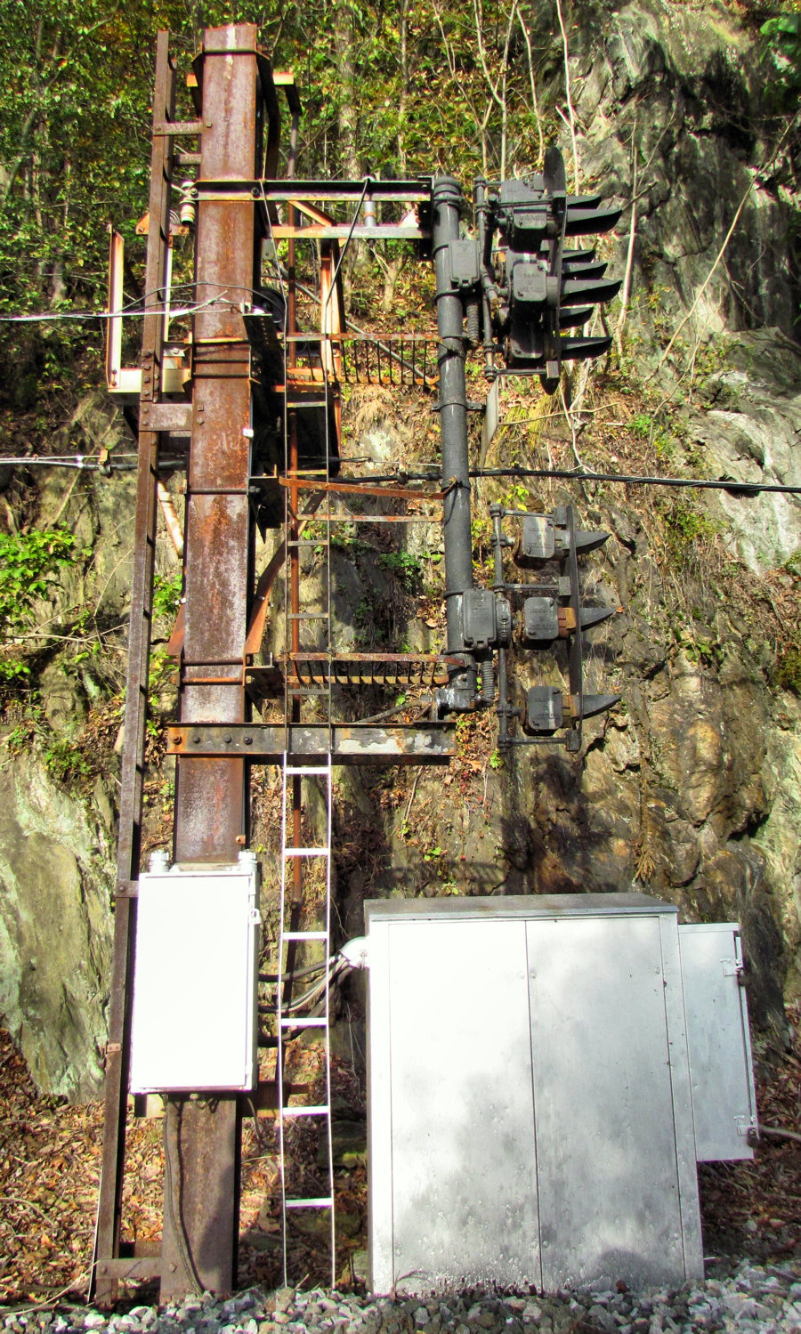
The interlocking is located in an extremely remote area with no road access. It can only be reached via a hike from Susquehanna State park or by boat. Here we see the eastbound signal gantry at CP-MIDWAY built out of a two track catenary support. Both signals were controlled from Lever 234 in COLA tower.

The signals have both been repainted, although one can tell the underlying surface was not properly treated and the new paint is already starting to flake. One interesting feature is the Stop and Proceed marker on the main track 234L signal, which NS had removed at a number of similar interlockings during the refurbishment drive. The 234LA siding signal features an economy style lower head lacking a Restricting \, instead relying on the Stop and Proceed lamp in the center.

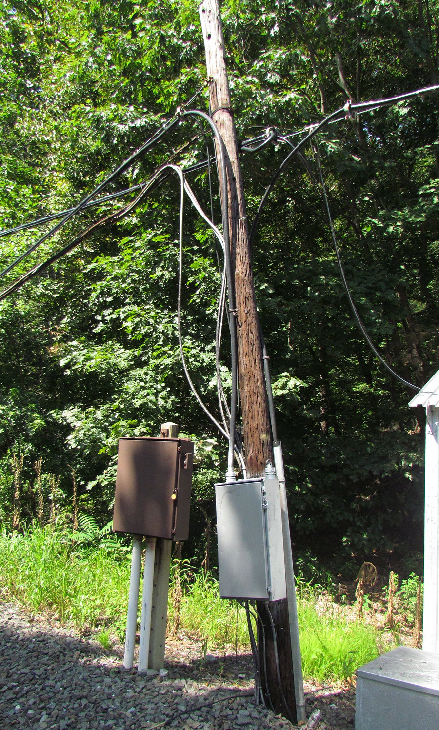
The old power supply is located between the eastbound signal gantry and the relay hut. As I have mentioned before the 6.6kv 100Hz signal power supply was replaced in favor of low voltage taps to the nearest utility pole. Below the power supply platform (still holding its original transformer) are the decommissioned CTC/telecom pole line and the bundle of signal cables running to the eastbound gantry.

The CP-MIDWAY relay hut has also gotten a nice new coat of cooling silver paint in addition to a satellite dish to replace the dying pole line.

The 504B code line that was replaced during the latest refurbishment was of the PVC wrapped telecom variety that has been in use since the 1960's. The 2011 catenary pole removal process saw much of this cable get scrapped as well, but a segment survives between HOLDWOOD and MIDWAY, for slide fence and block state transmission. In addition to CTC codes the line also carries telecom circuits for the signal post telephones that were common before the use of radio relay networks. Here we can also see the still used cloth wrapped interlocking cable bundle originating from the relay hut for its run to the eastbound gantry.
The relay hut is directly adjacent to the lever 233 switch.

The M23 electric point machine and the switch itself was also refurbished. Turnout speed is Medium (30mph).

Opposite side of the MIDWAY relay hut showing the service door, battery box and auxiliary relay cabinets.

Here is the current interlocking power supply which runs on utility poles heading to the west. The poles appear to have a few years on them so I suspect they were installed to supply the electric point heaters and NS just went to that power instead of their own by installing a 60Hz to 100 Hz frequency converter.

Here we see CP-MIDWAY looking west from the 234R signal. Because of white periods on Amtrak's NEC, there is very little traffic during daylight hours and therefore the signals all remained at Stop.

This combines the features of the 234L and 234LA signals with a full upper head and economy style lower head with Medium speed routes. Note the 'SP' plate for the slide fence between here and the C237 automatic. Speaking of the C237/238 signal, until the re-signaling project there was no westbound signal on the siding at the C238 location. This created a moderately long 3.3 mile block, but also required the westbound signal at CP-MIDWAY to inform trains of diverging movements at CP-HOLTWOOD. Trains making back to back diverging movements would receive an Approach Medium on the 234R at MIDWAY (although it would be possible for trains to diverge under Medium Clear and then get a cab signal drop at the C238 non-signal).

Here we see the proximity of the sheer rock cliff to the Port Road and its infrastructure. The electrified territory signal mounts used a dual platform system that can be caged in to protect workers from coming in contact with the overhead lines. Access between platforms was accomplished via hatches.

Alright, that's enough interlocking talk for one day. Time to move on and cover some block signaling locations. Between CP-MIDWAy at ~MP22 and CP-WEST HARBOR at MP13 there are three automatic blocks, each about three miles long, which appears to be the standard on the Port Road.
The first of the ABS signaling locations is C188/189 located just east of MP19. This signal matches the pattern of many other ABS signals on the Port Road / Enola Branch where single pole catenary supports are employed. Here one signal is mounted on the mast in the same manner as CP-MIDWAY's 234R while the other is given its own mast. Looking east towards the C188 mast signal we can see this pattern first hand.
The single head C188 ABS mast signal is displaying a Clear indication and is painted in the PC/Conrail style with the silver base. The river side of the track is seeing some ballast erosion from NS MoW trucks using it as an impromptu road.
In the other direction we see the catenary pole mounted C189 signal, which is dark for a reason I will get into later.

The C189 signal is the distant to CP-MIDWAY and supports a lower head | for Approach Medium indication. In the foreground we see the relay cabinet and battery box. In the background the remains of the catenary supports can be seen. From what I could tell the CTC code line is in service for transmission of block state between signal locations. In addition to it being left in place I could not hear any audio track circuit whine.

Here we see the old and new power supplies. The old power supply is of course in evidence by the platform and rusty transformer. The new power supply consists of a small twisted pair of low (120-480v) power running from the nearest utility feed about 1 mile to the west.


Here we see the C189 signal mounted above the relay cabinet. The pole line circuits tuck in in the side of the catenary support I-beam and then run down into the relay box. Before the refurbishment the code line was run into the small silver interface box located low on the cat pole. However at all the signaling locations these taps have been cut and the tables now run directly into the cabinet.
As a special audio-visual bonus here is a video showing off some of the sounds generated by the electromechanical signaling plants at CP-MIDWAY and the MP 18 automatic. The 180 and 75 ppm ticking noises are from the cab signal code generators pulsing out codes for Clear and Approach respectively.
As we reach the last signaling location to be covered in this set I am going to throw in one of the 2004 photos just to provide a reminder of how things looked before the re-signaling and refurbishment projects of the 2009/10 time frame. The C156/157 automatic signals are a further three miles from the C189/188 set. C156 shows some NS improvements in the form of a new 'SP' plate, but the signal head is badly rusted. The pole line runs into the small interface box at the base of the cat pole and the 6.6kv power supply is in service and hooked up to the transformer. Also note how the C156 signal is dark in this photo.
.JPG)
Here we see a closeup of the C156 signal 10 year later, lit up this time and displaying approach. The old power supply has been disconnected, but the rusty signal head has seen a new coat of paint.

The C157 signal is of the mast variety and in this photo can be seen displaying Clear. If you are wondering what is going on with which signals are lit and which signals remain dark, I was also a bit confused until I realized that the signals are approach lit only in the direction opposing the established current of traffic. These signals had what the PRR considered to be reliable power and therefore they felt no need to use full approach lighting, however power was still at a slight premium so approach lighting was provided for signals opposing the flow of traffic. This simplified the logic, saved power and made it easy for workers to determine which direction a train might approach from.
This somewhat unique application of approach lighting became apparent when traffic was thrown by the dispatcher while these photos were being taken causing the C156 signal to change from Approach to unlit Stop and Proceed and C157 to change from unlit Stop and Proceed to Clear.
The effects of this chance was captured on video in the form of more electro-mechanical cab signal code generator sounds starting with a 75ppm code for Approach that changed to a 180ppm code for Clear.
C157 also received a Conrail era upgrade to a Safetran style PL head. The NS rehab replaced the signal cable to one that ran outside of the signal mast and base. Not sure why running signal wires up through the concrete base and the mast were once popular, but they certainly make fixing a fault much more painful.
Relay cabinet and battery box. The handles marked C366 are for the isolation switches for the signal power supply. When trees or whatever would cut the signal power, maintainers could use these section switches to isolate the break then restore power from the nearest traction substation.

Here we again see the new and old power supplies. The old supply is in the form of a transformer that is at least being honest about its PCB content and the new supply is another 120-480v twisted pair running a mile back east to the nearest utility connection.

That's it for this installment of Port Road trips. Next time we will feature both ends of the Pilot siding and the MP9 automatic signal location.
No comments:
Post a Comment