Search This Blog

Monday, February 29, 2016

Switch Position Indicators

Switch Position Indicators are to railroad signals as Uber is to a taxi.  It serves basically the same purpose, but without the high cost and pesky regulation.  Switch Position Indicators (SPI) are exactly what they say on the tin, indicators (I'm focusing on the illuminated ones here) that indicate the position of an attached switch, either normal or reverse.  As they are not part of an interlocking, the SPI is typically mounted on or near the switch and broadcasts its indication in both directions simultaneously. The typical colors are green for normal and yellow for reverse.  Red is not typically employed since switches SPIs are attached to are usually trailable so there is indeed no wrong way to go through them.


Here we see an old US&S ES series SPI modified with LED lamps.  Previously centrally mounted electric bulbs would have shown through in each direction.  Out on the main lines, hand throw or spring switches would be fitted with kerosene lanterns that would be mechanically rotated 90 degrees to indicate the switch position.  These were eventually replaced by reflective "flags", also mechanically rotated in accordance with switch position, but I am focusing on the electric variety.


Electric SPI's like these were typically found in yards attached to trainable point machines with the SPI's indication being determined by a separate circuit controller.  If the switch points were on center, not valid for either route, the SPI would remain dark.


Here is a clearly lower quality GRS supplied SPI with plastic lollipop lamps indicating a reverse switch position.  This one is in light rail use and is attached to a standard GRS Model 5F point machine.  This switch is in use on the VTA light rail line and is actuated by the LRV's themselves via a transponder system.


Here we see a typical yard ladder setup with remote controlled switches and SPIs.  The apparent cheesiness of the indicators steps from the fact that they are not considered safety critical devices like normal railroad signals and don't have to be weather resistant, fail safe, etc. 


Now just because trains are moving at restricted speed doesn't mean that one can just shrug off derailments.  These units at Amtrak's Lumber St Yard in Chicago have a special third, lunar white, lamps that illuminates when something is over the switch and the points are locked.  I am not exactly sure of the mechanism that detects when a train is over the points (track circuit, treadle, inductive sensor) , but it appeared to work.


Outside of yards, spring switches were one of the earliest applications of SPIs on main line track.  Popular on pre-CTC single track lines, spring switches eliminated the need for trains to have to re-line siding switches for the main and in certain applications eliminated any need to stop and throw at passing points all together.  However where such lines lacked ABS signals to protect against misaligned points, SPIs were the answer, giving oncoming trains moving at above Restricted speed assurance they weren't about to careen into a siding.


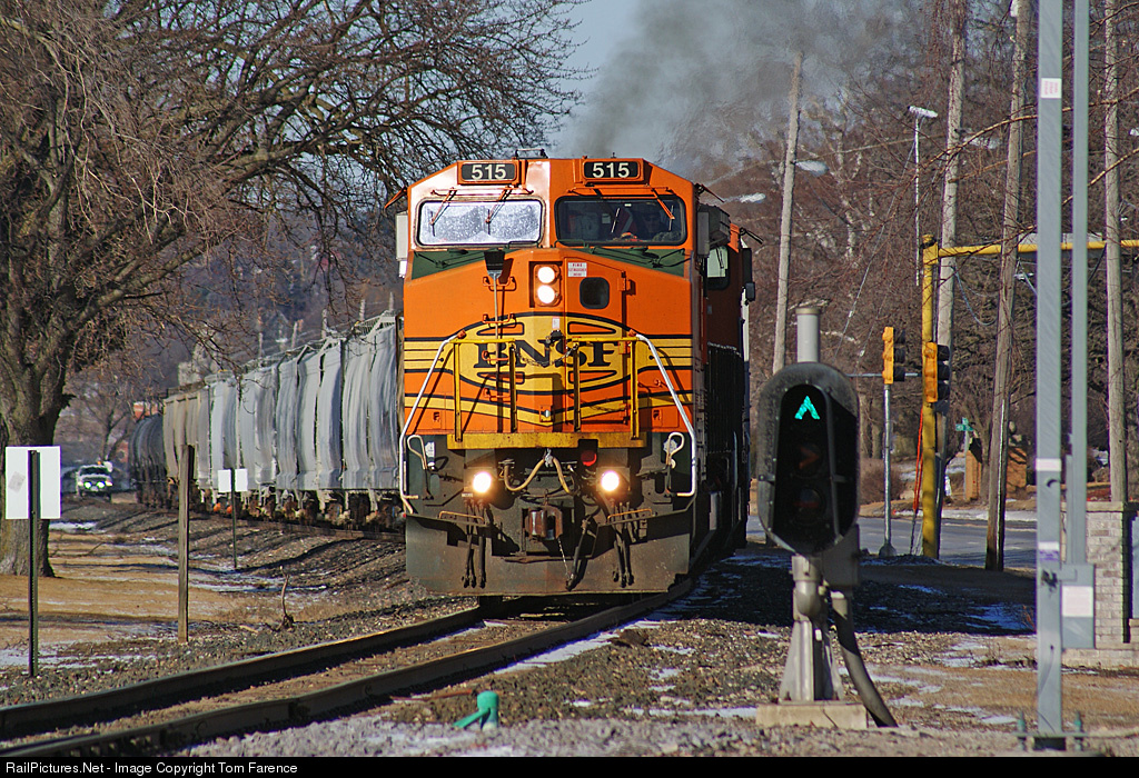
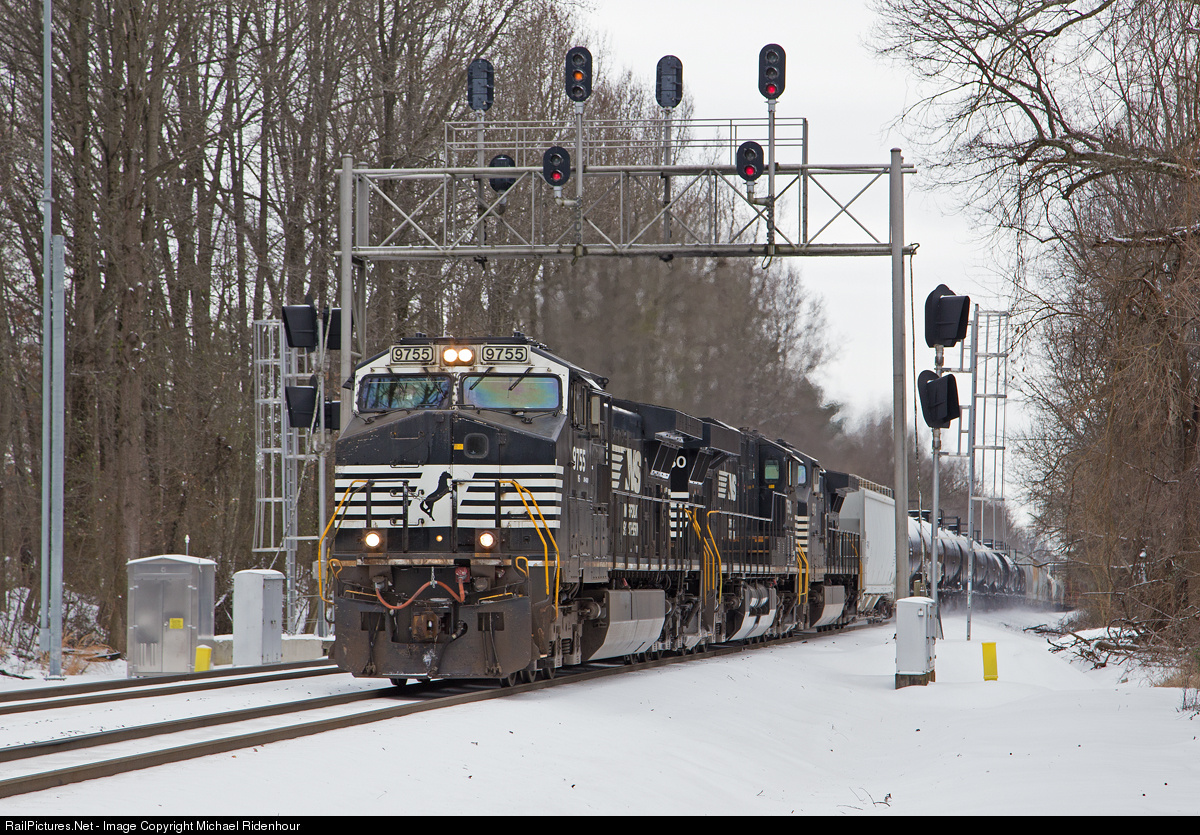
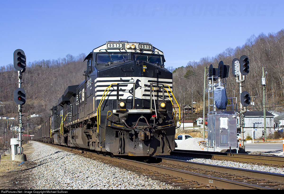
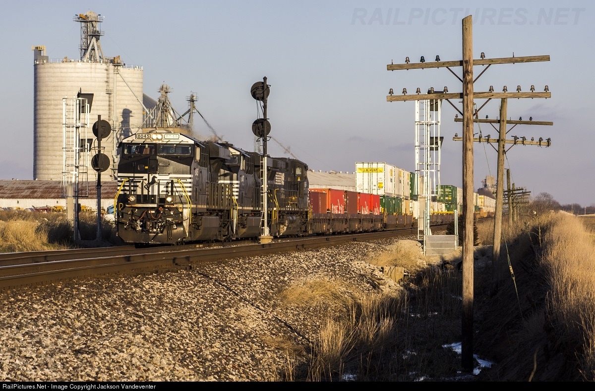
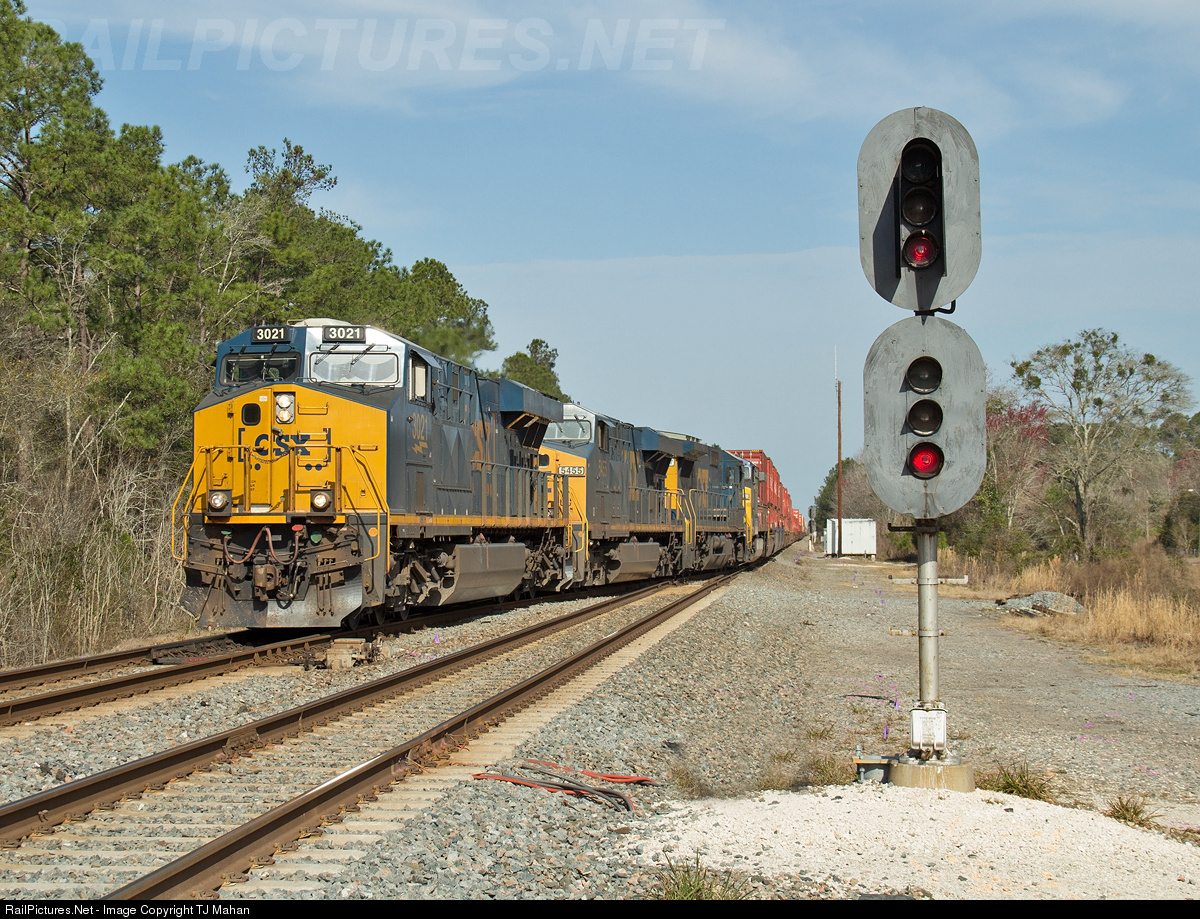
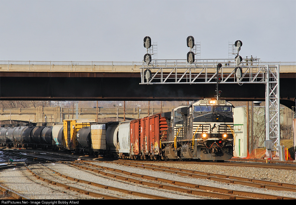
Lately, railroads are getting increasingly bold with their use of indicators on unsignaled secondary tracks.  Non-interlocked junctions might require sizable freight trains to have to stop and line a switch, possibly multiple times as cars are set out or backup moves made.  Not to mention the hassle of having to wait for a member of the crew to walk to train after restoring a hand throw switch.  Equipped with radio or transponder controlled switch machines just as we saw on the line rail line, these non-interlocked power switches are being fitted with a slightly higher class of SPI.  This example makes use of a standard Darth Vader type signal head with modified lamps showing normal, reverse and on-center positions.  As you can clearly see, SPIs do not convey block information.


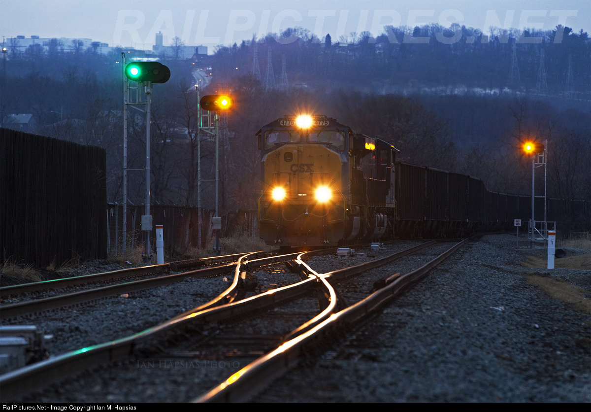
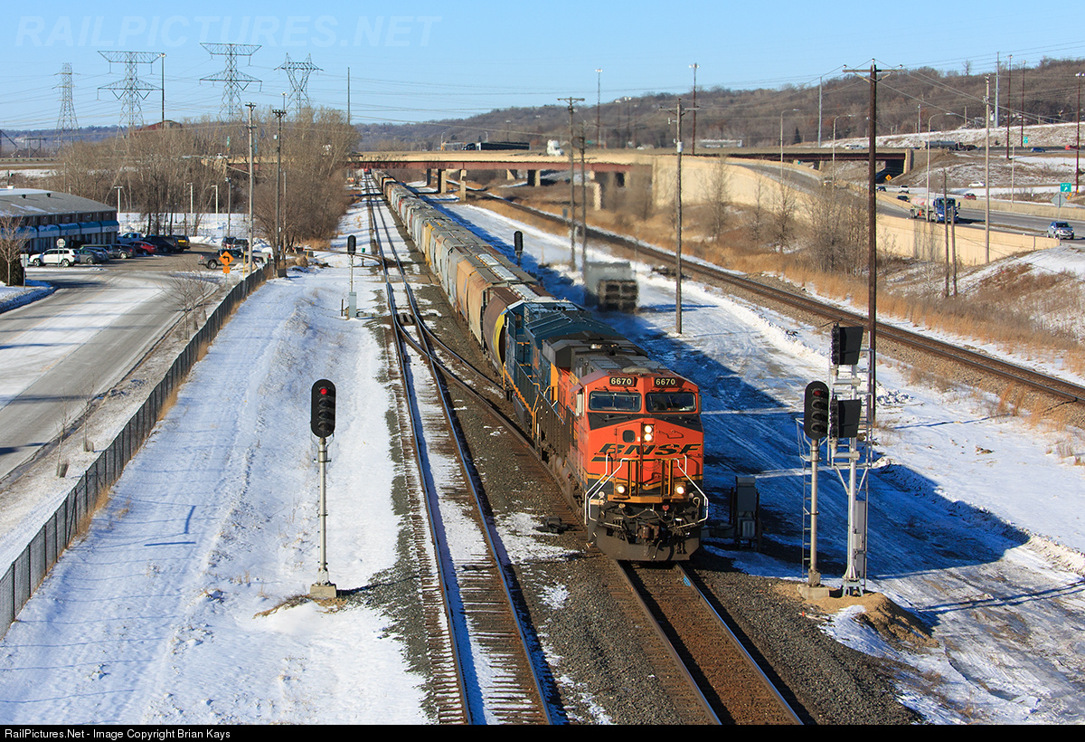
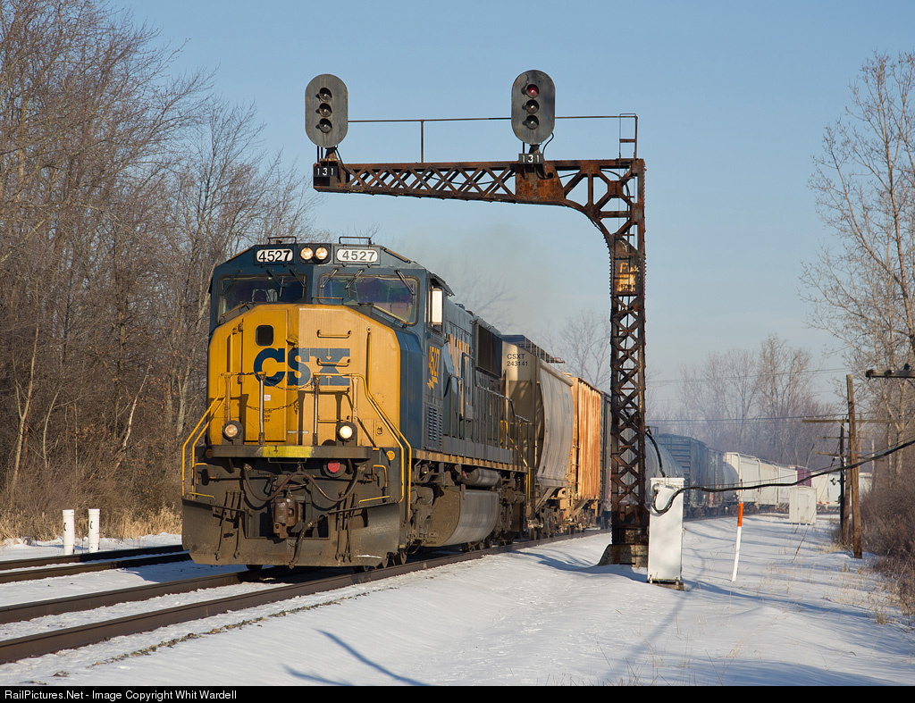
Here we have perhaps the pinnacle of SPI craziness, a full crossover with M23 point machines protected by a full past SPI .  As with BNSF above, CSX  has sought to differentiate their signal-like SPIs from regular signals.  Their method is to use CNW style horizontally mounted signal heads.  This practice has been picked up by a few other roads while another popular method is to use ovoid signal heads with the cheap style signals seen in the Amtrak photos.

That's it for today.  This wasn't meant to be anything really in depth, just a little heads up for when non-interlocked interlockings appear on a rail line near you.

Tuesday, February 23, 2016

Newsruary

Alright, let's see what's going on in 2016.  On the former NY Central main line the CSX re-signaling effort is reaching towards Buffalo as seen here at Corfu and MP 402.


 Hey, surely aluminum tubular signal bridges have a place in the 21st century.  Hmm, guess not.


 Southern style masts with Safetran clamshells aren't even safe in mast form like these examples on the old N&W main line.  I'm thinking that 2008 PTC law should be called the signal uniformity act.


 Of course NKP re-signaling is nothing new.  This time an intermediate example with H-5 searchlights.


 At least one can't say it all about saving $.  These Soo Line economy heads are also playing second fiddle to Darth Vader masts.


New signals are still creeping up the old C&O Northern Division with this cute cantilever a recent victim, however they are hanging on in a few places.


This Darth Vader cosplayer didn't stand up to scrutiny by CSX's signal team.  Replacement bases are already in place near Jacksonville.


In what I think qualifies as good news, the re-signaling at CP-BETHLEHEM is taking way longer than I had expected so...yay?


Yeah, no real good news this month.  :-(

Monday, February 15, 2016

PHOTOS: OVERBROOK Interlocking

So it's been a while since we last visited the PRR Main Line and this time I have something special.  OVERBROOK interlocking, straddling the border between the city of Philadelphia and Montgomery county, is not only an important part of past and present Main Line services, it is also an active interlocking tower dating from 1926 with all of the PRR trademarks on display for all to see.  OVERBROOK and its interlocking is highly accessible, being located in the middle of a commuter station.  However what makes this tower truly special is that in the 2003-2004 time period I was able to visit it on several occasions and spent hours inside watching the operations and even working the U&SS Model 14 machine.  This will be the first of a three part look at OVERBROOK, the first covering OVERBROOK interlocking, the second OVERBROOK tower (inside and out) and the third OVERBROOK's CTC territory.


OVERBROOK is the first typical crossover interlocking on the Main Line after ZOO.  It was later expanded to include the west end of the old Belmont Freight yard and CTC control over the junction with the old Schuylkill River branch at VALLEY interlocking, but the core of its operations were the 4-track crossover tracks that ran the length of the station.  Here is a 1972 interlocking diagram showing OVERBROOK's territory at the peak of its responsibilities.


The original 4-track crossover part of the interlocking controlled by the US&S Model 14 interlocking machine dates from 1926.  In 1941 OVERBROOK assumed control of the west end of PRR's 52nd Street Yard, situated between the main line passenger tracks stretching between OVERBROOK and ZOO by means of a direct wire relay interlocking. Not a separate interlocking in its own right, this new territory was made part of OVERBROOK interlocking itself, but referred to as the "Woodbine" section of OVERBROOK on signaling documents.  OBERBROOK was also given CTC control over the aforementioned VALLEY interlocking on the Main Line and JEFF interlocking on the Schuylkill branch.  Woodbine, VALLEY and JEFF were all controlled from a new US&S unit lever CTC machine installed on the operator's desk in the bay window and is the reason OVERBROOK is shown with two interlocking machines on the diagrams.  Finally, in 1964, OVERBROOK was given one last CTC interlocking, MANAYUNK, when the Schuylkill branch was cut back to a single track at that passenger station.  Here is how OVERBROOK appeared after 20 years with Amtrak in 1992.


You can see that Woodbine and the old 52nd St yard complex has been greatly diminished as freight traffic left Amtrak territory in the 1980's.  VALLEY has also been simplified, JEFF has been transferred to SEPTA control and MANAYUNK no longer exists after passenger service was cut back to Cynwyd.  Finally here is how OVERBROOK's territory looks at the time of this writing in 2016.


The biggest change is the route that Main Line passenger track 4 takes between ZOO and OVERBROOK.  Previously it had flown over the freight yard complex on a long truss bridge at VALLEY interlocking.  (That is how freight traffic was able to access the yard from the middle tracks at OVERBROOK).  However in the early 1990's twin crises emerged with a common solution.  PCB from the former PRR electric MU shoppes at Paoli had contaminated large parts of three counties and the VALLEY flyover bridge was rapidly deteriorating and could no longer support passenger train speeds.

Realigned track 4 (far left) and the old VALLEY flyover.
The solution was to shift track 4 over to run adjacent to tracks 1 and 2 on the site of the former freight yard and then build a new SEPTA MU maintenance facility on the newly available space.  This had the side effect of requiring three new interlockings, STILES, PAXON and WOODBINE (not to be confused with OVERBROOK's Woodbine section mind you), which would then be controlled by ZOO, as it had a leverman job to support the extra workload.  The effect on OVERBROOK proper was the further truncation of the Woodbine section, removing the #14 and #15 running tracks the 017 switch.  This left only a triplet of signals, the 20R and 018R, and a single switch, the 019.  The reason for the leading zero was to differentiate levers on the CTC machine from levers on the Model 14 machine.


The westbound 018R signal at OVERBROOK's Woodbine section.
As I mentioned before, OVERBROOK's Woodbine section was located directly adjacent to the new Amtrak WOODBINE interlocking, but confusion was minimized through the use of colorized position lights on the newly hardware.

1941 PRR PL vs 1994 Amtrak PL. Taste the difference!
 Originally intended for terminal freight moves, the 019 is a slow speed switch with Slow Approach displayed for diverging routes on high PRR signals.  The best indication the 018R can give is Approach Medium for a diverging route over the 17 switch at OVERBROOK.

OVERBROOK 018R displaying Slow Approach over the 019 switch reverse.
Eastbound movements at OVERBROOK's Woodbine section were provided with a 4-track signal bridge hosting signals for the center tracks 2 and 3.  In 1994 the bridge was re-purposed to also support WOODBINE's eastbound home signal as well.  Tower, between OVERBROOK and ZOO, all 3 tracks are technically bi-directional, although reverse movements on #1 track will encounter a string of PL dwarf signals displaying slow speed indications.  Prior to 1994 track 4 was only signaled for westbound movements, but this was upgraded when the three new interlockings were added. As you can see, due to its slow speed and somewhat redundant nature, the track 3 route over 019 switch isn't used much, but the famous 4-track main line does start here.

I should also mention that OVERBROOK was the site of a 1954 experiment to equip the upper head Stop position with red lenses, a measure that was later adopted by the Penn Central and Conrail.  However Amtrak did not embrace this modification (at first) and OVERBROOK was converted back some time after 1976.

OVERBROOK 20R displaying Slow Approach over the 019 switch reverse.
WOODBINE interlocking, that provides a seldom used westbound exit from SEPTA's Overbrook maintenance facility, is notable for the frequently displayed Slow Approach indication on its westbound mast signal.  This is due to OVERBROOK's rather unique layout involving pocket tracks.


Only a few hundred feet separate the eastbound Woodbine signal bridge from OVERBROOK's westbound signal bridge.  Despite all 4 tracks being technically bi-directional, only tracks 2, 3 and 4 (from left to right) are given high signals on the bridge as reverse movements on 1 are exceedingly rare and made at slow speed (no cab signal code).  However they are still made under signal indication without a track warrant. Track 2 is Rune 251 in the eastbound direction west of OVERBROOK so its 14R signal does not provide straight route indications.  The 12R and 8R signals on tracks 3 and 4 do have Clear indications (as seen on the 8R) however you might notice the absence of an Approach / on the upper head.  This is due to the short distance between the westbound gantry and the pocket exit signal on track 4 or the interlocking exit signal on track 3.  While most railroads would use speed control followed by a straight approach for short signal blocks, the PRR was on of the few that would follow it up with a Slow Approach.  This was due to the availability of a slow speed indication on standard high signals.


Friday, February 12, 2016

No Clipping

As the exciting future of solid state lighting increasingly becomes the present, some of you may have noticed that LED lamps are a bit more, sterile, for lack of a better term, than their incandescent predecessors.  Now I am not talking about the narrow spectrum or the supposed "coldness" of the light, but specifically the way that LED's behave when flashing.


When flashing LEDs are very binary in operation.  On, off, on, off.  As soon as the voltage crosses some threshold the LED lights up, as opposed to an incandescent bulb that has distinct rising and falling edges as evidenced in the following montage.


But wait, perhaps LED's are not to blame.  Amtrak's FAIR interlocking was an early test for retrofitting incandescent position light lamps with LED light sources and its flashing indication aren't quite so harsh.


If you are wondering if this effect is caused by the flasher relay or other interlocking hardware I actually came upon a natural experiment that is only possible in Position Light territory.


As Amtrak's Train 19 rolls past the 6AE signal at FAIR interlocking, the two green PL lamps appear to be flashing out of sync, but what is actually occurring is that the top lamp is set to flash in a clipped LED style and the bottom is flashing in a ramped incandescent style.

I asked some electrical engineers and they suspected that the magic is all with the details of the LED's local power supply.  It appears that the early units at FAIR have a capacitor tied into the circuit, slightly delaying the flash cycle as it charges and then delaying the cycle as it discharges. The other (cheaper?) supplies appear to only supply a fixed voltage or nothing.

I don't know what is driving the clipped style LED signal lamps appearing all over the world.  It might be cost, or simple ignorance or even a belief by the signal vendors (or component purchasers) that the more binary behavior is desirable.  Hopefully, as was the case with Amtrak's initial LED tests, some railroads will request components that behave in a warmer, more analogie style.

PS: If anyone has EE experience and knows how the power supply circuits are constructed, please share in the comments.