Search This Blog

Tuesday, December 31, 2013

Heya Toots! - The Story of the Interlocking Horn

Anyone who has spent time in towers or gotten up close looks at CTC consoles or video displays may have noticed the presence of buttons (or icons) labeled horn or whistle or emergency horn.  Occupying the same general category of ancillary functions as point heaters, maintainer call lights and low air alarms the "Interlocking Horn" is a vestige of a time long past when communication was intermittent and unidirectional, but still serves a purpose to this day.

The concept of an interlocking horn is pretty simple and basically serves as a method for the dispatcher or operator controlling the interlocking to communicate with train crews or other personnel who might happen to be in the area.  As you may have already surmised the use of binary state sound generators to transmit information have been generally supplanted by radios and mobile phones, but interlocking horns can still be found mounted on present day relay huts installed up through the current day (2014).

 I first learned of interlocking horns in a discussion of Pennsylvania Railroad block operation where they were described as being used to stop trains in an emergency if the operator became aware of an unsafe condition, but the train had already passed the controlling signal.  The operator would sound the horn and upon hearing it either the locomotive crew or (more likely) the rear end crew would bring the train to an immediate stop and use a line side telephone to communicate with the tower operator.  The practice always sounded a bit dodgy to me as trains are a loud place to work and unlike a visual signal it is a bit harder to verify that an alertness signal is not being sounded.  Still, horns can be made very loud and with 2 or 3 people riding in the caboose it was likely that at least somebody would catch the signal that the bridge ahead was out.  Still, a quick glance through the current NORAC rulebook shows that interlocking horns are a bit more complicated than that with a vocabulary that approximates the old trainline communication whistle system that was ultimately supplanted by crew radios.  Here is the exact text of NORAC rule 18.

18. Horn Signals Used by Dispatchers or Operators
The following are horn signals that may be used by Dispatchers or Operators at interlockings or other designated points. The signals are illustrated by “o” for short sounds and “—” for long sounds.
SOUND INDICATION
(a) — All movements within interlocking limits must stop immediately.
(b) o o Normal movement may be resumed after receiving the proper signal or permission of Operator.
(c) o o o Whistle or Horn test.
(d) o o o o Signal maintainer must call the Dispatcher or Operator.
(e) o o o o o Electric traction employee must call the Dispatcher or Operator.
(f) o o o o o o Trackman must call the Dispatcher or Operator.
(g) A bell, horn, white light or oscillating white light at remotely controlled signals and interlockings indicates that any employee, except on moving trains, must immediately communicate with the Dispatcher or Operator.
 Long story short the interlocking horn was intended to stop train movements or get some sort of wayside employee to call the dispatcher or operator.  In my discussions with current operators and dispatchers I have found that in modern times the horns are rarely used in this capacity.  More often than not they are used to scare children or other trespassers off the tracks or perhaps to warn nearby employees of approaching train movements although in those situations a full time whistle/safety man is often on had to do the job.


Naturally the Pennsylvania Railroad made frequent use of interlocking horns due to their embrace of and electro-pneumatic interlocking plants.  With a source of compressed air on hand, it was trivial to attach a horn to the side of the tower and then run a wire to a button inside.  Due to the length of some interlockings one horn would not be sufficient to provide warning at both ends so multiple horns were used with one being placed on the tower and others being mounted to remote air compressors or other air handling equipment.


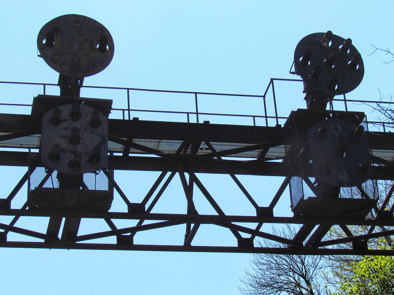
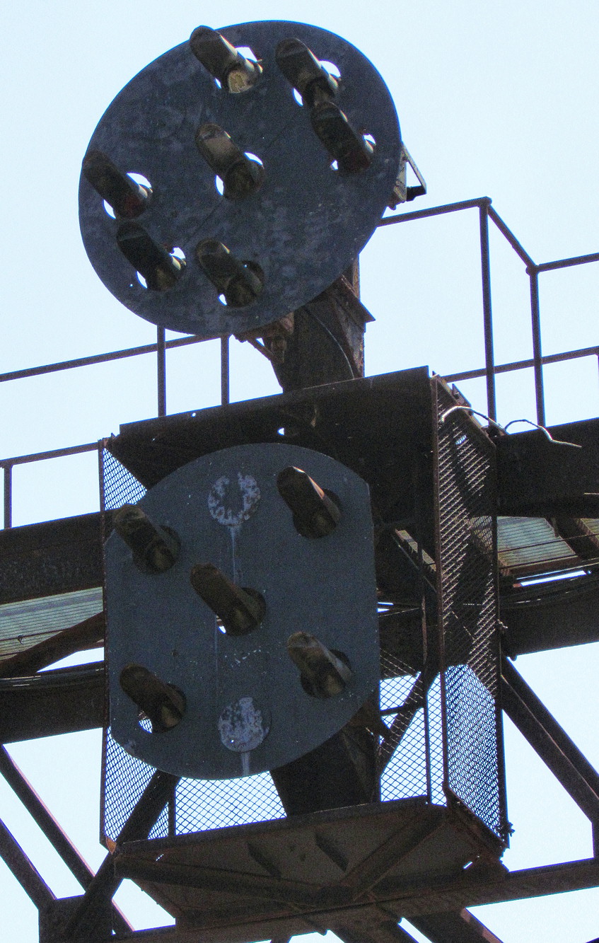
Horn buttons in towers could be mounted on their own as seen in OVERBROOK, but often times they were placed on a panel with numerous other buttons for lights or communications or special interlocking functions.


The most common horn configuration makes use of two bells, one pointed in each direction to provide maximum coverage.  Usually the horn bells are symmetrical, but there are some examples of the horns being asymmetric.


The most amazing thing is that the concept of the interlocking horn outlasted the interlocking tower era itself.  Like point heaters and maintainer call lights interlocking horns were mounted on CTC era relay huts and hooked up to the code line for dispatchers to sound remotely.  Still, this isn't entirely surprising seeing that portable radios were not reliable until the 1980's and dispatchers still needed a way to get MoW crews in the area of a relay hut to phone home.  Where electrically operated switch machines removed the need for an on site compressed air plant, "klaxon" type electric horns were employed. As you can see with this example at NORGE interlocking on the CSX Peninsula Sub the small single bell was clearly intended to communicate with trackside workers and not the train crew.

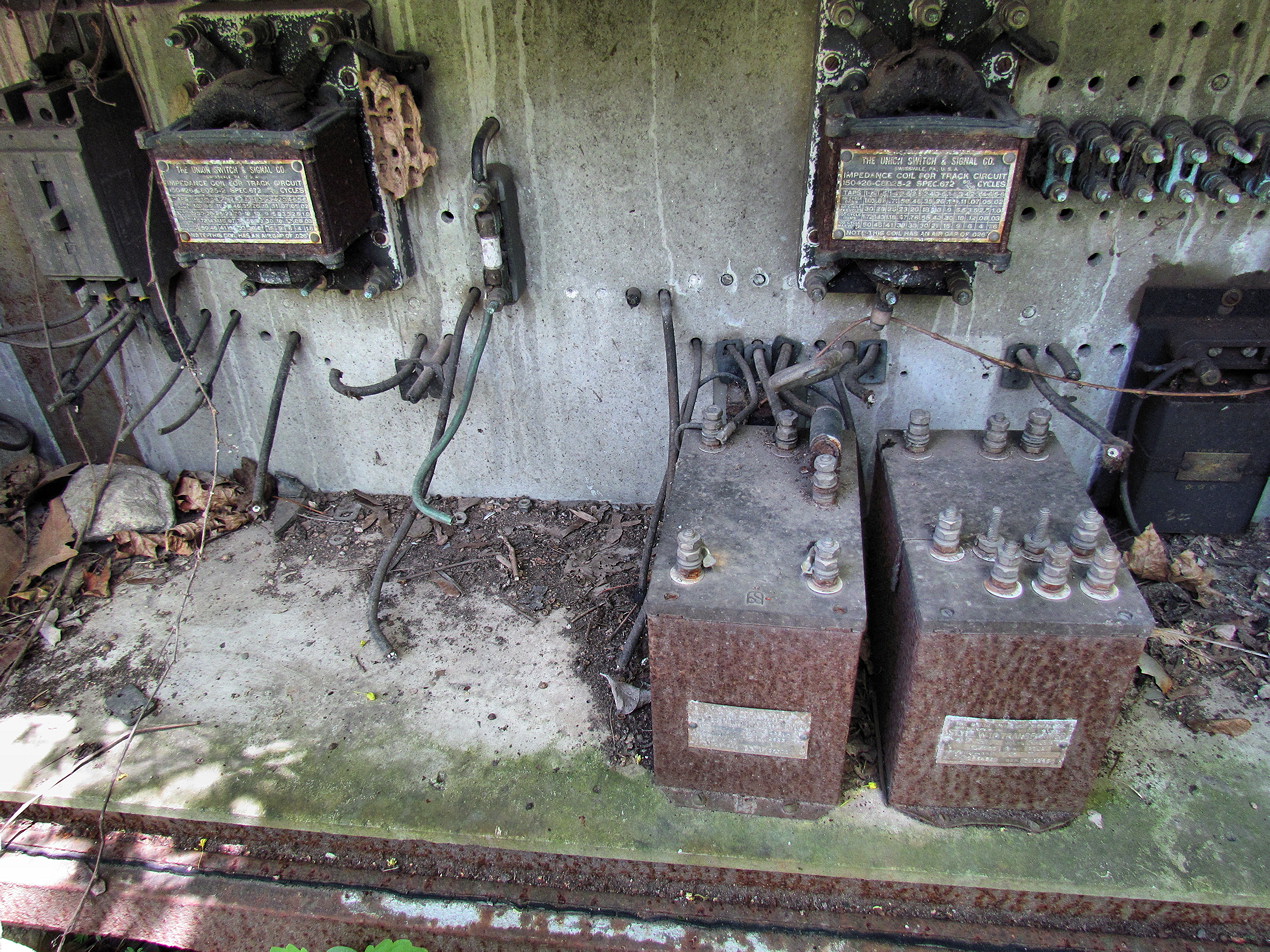
Insect infestation is a problem in Tidewater Virginia.

Unfortunately as these and other 1970's era CTC relay houses are being replaced the new CSX standard hut does not provide for the continued employment of interlocking horns.  Even in the 1970's use of interlocking horns was not uniform as can be seen with LEE HALL interlocking being provided with an slender truck style horn while only two miles away WEST LEE HALL was not provided with one at all.

Truck horn and exposed cloth and tar insulated wire bundles.  Classy.

 As technology marched on so did the design and employment of the horns used at interlocking.  In fact some could barely be considered horns at all like this loudspeaker device mounted to the relay hut of LEADENHALL ST interlocking in downtown Baltimore, MD.


Interlocking horns were not just the purview of the PRR or former Chessie system lines.  Here we see a relay hut at CPO-4 on the D&H Colonie Sub which had been recycled from CPF-130 on the Freight Main Line sporting a small, 100% external klaxon type unit.


 New Jersey Transit is perhaps one of the last believers in the concept of the interlocking horn.  Here is a 2003 photo taken of the recently installed ATLANTIC interlocking relay hut in Atlantic City New Jersey with a compact twin bell unit mounted squarely on the side.

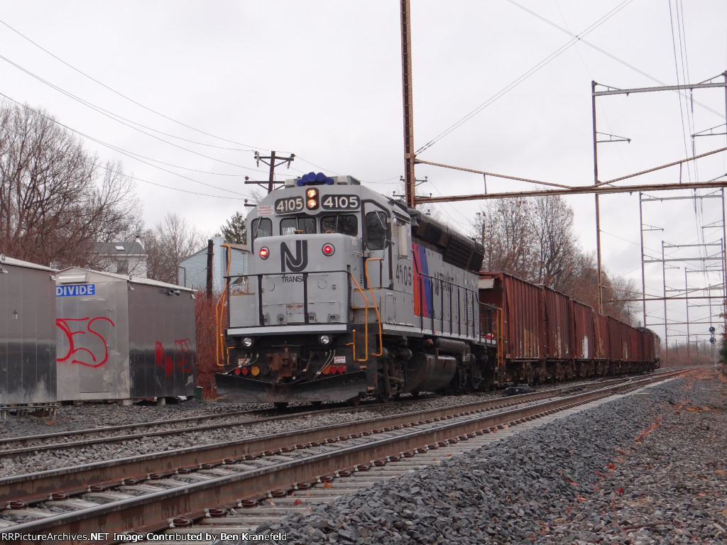
NJT is also committed to the lineside telephone box.
A decade later we see that NJT is still at it with a similar unit installed on the side of the brand new (2013) DIVIDE interlocking in Pennsauken, NJ.  A similar horn was applied to the new JORDAN interlocking two miles to the east.

http://www.rrpicturearchives.net/showPicture.aspx?id=3708211
Yes, that is a new relay hut design.
I am sure if I scoured my records thoroughly enough I could find other examples of interlocking horns on other railroads, but I am pretty sure you get the point.  The takeaway is that the next time you are out shooting some classic signal, make sure you get a nice closeup of that odd looking horn on the side of the relay house.  They are yet another disappearing vestige of our signaling and communications past.

Tuesday, December 24, 2013

PHOTOS Port Road Trips - WAGO Interlocking

In our third episode of Port Road Trips we will examine the Conrail era WAGO interlocking which replaced the older CLY interlocking as the southern endpoint of the Northern Central Main Line / Enola Branch parallel running configuration.  The replacement of CLY was motivated by the general redundancy of the NCRR line and the replacement of the 2x2 configuration with a single 2-track ABS line running on the Enola Branch alignment.  While the NCRR no longer ran through to Baltimore, there was still local freight traffic to York and other points in the vicinity so a new interlocking was constructed closer to where the Enola Branch and NCRR lines originally met at Wago Junction  Here is how this section of the line appeared in the 1998 Conrail Employee Timetable. Note that as sometimes happened on Rule 251 ABS lines the interlockings were not prefixed with CP.  I don't know why that was, but for the purposes of this writeup I will follow the same practice.


For a more detailed view of WAGO interlocking here is an interlocking chart dating from 1997.  There are a number of differences between this chart, the 1998 timetable and the facts on the ground in 2012 and I will get into them as we move through the interlocking. All of the differences are of the "stuff being removed" variety" so the chart has everything that was ever part of the plant.


The changes involved in the switch from WAGO to CLY actually begin between the two points with a Block Limit Station named GOLD being established at MP 56.  This was installed to allow trains requiring needing to move eastward at WAGO to pull out onto the main line and then reverse. With GOLD the dispatcher would not have to hold the track all the way to STELL or use a less precise milepost "station" on the Form D.  GOLD was located just east of the NCRR MP 72 automatic.


WAGO interlocking was typical for 1980's Conrail interlockings, making use of existing signaling arrangements as much as possible.  In this case the new interlocking was situated at NCRR milepost 67 ABS signaling location south of CLY which allowed reuse of the old PRR signal bridge. Like the other 4-track ABS signal bridges on the 2+2 section this one was elevated on risers (note the old milepost) to clear the overhead catenary when they were installed in the late 1930's and due to the NS re-signaling this is probably the only surviving bridge of this type.  Note the disused mounting for the westbound Enola Branch ABS signal at the right of the gantry. 


For East (South) bound train WAGO presented a crossover from track two to 2, an interlocked lead to the  Brunner Island Power Station and a connection to the Northern Central, now known as the York Secondary.  Both the power station and York Secondary tracks were non-signaled and would normally result in Restricting indications.  As you can make out on this backlit photo of the eastbound signal bridge the Track 1 "2E" signal is equipped to display a Slow Approach indication as well as restricting.  As the interlocking is quite long this was most likley used with an "End of Block" sign when entering the York Secondary. 


The Track 2 "4E" signal likely displayed Slow Approach as well, but this distinction was obscured by the additional ability to display Medium Clear and Medium Approach indications for wrong-railing trains crossing over to the "right" direction track.  If you are a bit confused here since I already said that WAGO only contained a single facing point crossover you would be correct.  WAGO was originally built with a full set of crossovers and later had one removed due to infrequent use.   The full lower head on the 4E signal is an artifact of this older configuration.


 The old ABS relay cabinet is still in place at the west end signal bridge and still includes a few old signal transformers.


The only remaining crossover at WAGO, #1 switch, appears to have recently undergone some basic upgrades including roller mounted blades and additional electric point heating which includes loop heating elements under the points in addition to longitudinal elements on the rails.


The WAGO relay hut is again typical of Conrail practice being constructed of Corten "protective rust" steel and featuring a milepost number on the blue station sign.


Tuesday, December 17, 2013

DIY Interlocking Machine

I tend to prefer my interlocking towers and interlocking machines "in the wild" that means in service on a real railroad and not "in a zoo" (tourist line) or stuffed (in a museum).  Now while something like HARRIS tower and its PLC controlled Model 14 or SoNoToMo and its interactive lever frame are great fun in some way it would have been better had they still been in service, invulnerable to Chinese cyber attack.  However today I have discovered an interesting example of an interlocking machine that was neither caught for a Zoo or stuffed for a museum.  This one was hand built from scratch for a model railroad and while I don't think it would pass muster at GRS it is certainly better than what most people use on their layouts. 


Yup, you are seeing that correctly.  This person has built a replica GRS interlocking machine entirely out of wood, from scratch.  The best part is that it is being wired up to run the largest New York City Subway model layout in North Dakota. I'm actually nt exactly what if any interlocking logic it uses, but there are a while mess of relays involved so its not completely braindead.


I have to give major props to the wiring job as well. 


The builder would have actually prefered a US&S machine (and you can see some of the design elements), but the pistol grips were easier to implement and also control the model train stuff.  Still, I'm not complaining.

Saturday, December 14, 2013

Some Year End News

I've been building up a stockpile of domestic news items in additional to my recent international coverage.  Surprisingly CSX is not topping the list as instead we turn to the increasing rate of re-signaling on CN/CP.  This time the ax is falling on the CP C&M Sub which currently hosts Amtrak's Hiawatha route and was a haven for new-install searchlight type signals. This photo was taken at Wadsworth.

http://www.railpictures.net/viewphoto.php?id=461822&nseq=120

Here is a CN example on their Minntac Sub which consisted of one of the old Iron lines in the north of that state.  Again this was another supposed searchlight haven due to the backwater status and lack of PTC necessity.  :-(  This photo was taken in Wolf, MN.

http://www.railpictures.net/viewphoto.php?id=460449&nseq=702

Ok, now we can move onto to CSX.  Here the re-signalling effort on the Abbeville Sub have been moving westward through the Athens, GA area reaching the Harper Siding west of town.  Again another senseless project that is replacing a fairly new signaling system installed in the 1980's.  Here is the MP 517 auto laying dead and on the ground.  Luckily I have a friend in the area and forced her to drive me all over to document the classic SAL signals including 517.9.

http://www.rrpicturearchives.net/showPicture.aspx?id=3708634

This isn't really news, but just a view on the Philly Sub of a train taking a color light Medium Approach indication into the Van Bibber siding from the east.  This is another location I was able to document.


Sunday, December 8, 2013

Petone (New Zealand) Signalbox to Close

I don't normally do foreign (non-North America) signaling news simply because there is so much of it and it would require all sorts of explanations of how such and such technology compares to what most of the other readers of this blog are familiar with.  The small signalbox at Petone, NZ is special because not only has it been very well documented by the Hutt Valley signaling page, but also because both New Zealand and Australia see a lot of North American style signaling practices, even if it is by way of UK licenses of traditional US&S and GRS technology. Also like North America New Zealand is rapidly running out of manned interlocking towers so the loss of this one is worthy of note.

Petone signalbox showing the 67 signal displaying Clear for a Wellington bound train.
 The interlocking tower, or Signalbox in commonwealth terminology, is almost entirely North American in design with a familiar black CTC-style desk console and searchlight signals out in the field.  It is an all relay plant that today control controls two crossovers and one turnout for a branch line.  It is stunning that it has held on in service for as long as it has, even with just a single 12 hour shift.


 As you can see here in this photograph of the console the amount of territory and interlocking appliances under Petone's control has shrunk dramatically since it was built in the 1950's, especially in the Petone Station area.  I should also mention that Petone is CTC in the PRR fashion with remote interlockings on ABS signaled lines instead of lines with actual traffic control.

Click here for a higher resolution image.
Unfortunately, but not surprisingly, Patone box is being re-signaled and is finally closing on Christmas Day, 2013.  More unfortunately is that the new interlocking is going to use "tip over" LED signals and axle counters instead of track circuits because its always better to infer the location of trains than, you know, DETECT THEM.

68 reverse direction dwarf signal and its new replacement.  The line will be moving from ABC to CTC.
 Anyway if you happen to live in New Zealand make sure you get out there and grab some photos before the box closes.  You have no excuse thanks to all the nice sunny weather this time of year.  If you are interested in the re-signalling project check out this very detailed page here:

http://valleysignals.org.nz/petone/newpetone.html

UPDATE:  Friend of the blog  Sophisa, who lives in the Wellington area, actually went out and took a number of very nice photos for me including the outstanding high res CTC console shots.  Just goes to show what the ladies are capable of in the sausage fest that is railroading.  Thank you so much!!  You can find all her photos here.

What's going on here o.0
DOUBLE UPDATE:  Found a photo of the "new" PETONE CTC console.


Wednesday, December 4, 2013

Non-Conditional Cab Signal Drops

In the wake of the recent Metro-North derailment I wanted to share a few bits and pieces on non-conditional cab signal drops as a way to control train speed for non-signaling related reasons or to warn Engineers in advance of a particular hazard. While Cab Signaling or any kind of signaling is typically seen as a way to warn trains of dynamic hazards, there have always been cases where signaling has been employed as a tool to show trains for static hazards. Typically railroads have preferred to use line speeds for such static hazards as the regulatory issues and costs are much less. Case in point being equilateral turnouts where all routes get Clear signals and the restriction is listed in the employee timetable. However on speed signaled roads the most common use of signaling to control timetable speeds is seen with slow speed terminal trackage where all routes, straight and diverging, are signaled for 15 mph.

If one scours enough interlocking diagrams it is easy to find examples where what might meet the signaling definition of a "straight" or Normal Speed route provides a more restrictive signal indication in order to deal with a particular high risk speed restriction. One well known example was the former CP-WEST PITT interlocking on the Conrail Pittsburgh Line that retained its 15mph Slow Speed routes due to a sharp curve west of the Pittsburgh Station. Even after the interlocking was removed westbound trains still encounter an Approach Slow at CP-PITT or CP-EAST PITT before the MP353 automatic displaying Clear.

Signaled speed restrictions are certainly more expensive than signs or ink.
Technical signaling enhancements like IIATS and the British AWS both contained mechanisms for non-conditional activation, which had the benefit of being cheap to employ due to there being no need for attached power or logic in such situations. To this day there are a number of ATS protected speed restrictions on the former ATSF "Super Chief" route from Chicago to Los Angeles, even outside of ATS territory as locomotives on the route are generally ATS equipped.

1920's technology is sufficient to alert a drowsy Engineer.
This finally brings up the use of "phantom signals" or non-conditional cab signal drops to control train speed at high risk speed restrictions. I have heard this was employed in a number of locations by the PRR, but was unable to find any references for that, but the most notable use of this practice came from Amtrak in the result of the Back Bay Derailment in the late 1980's where a high speed Amtrak train approaching Boston at 100mph failed to brake in time for the sharp 30mph curve at the west end of the Back Bay station. As a result Amtrak agreed to install non-conditional cab signal drops at a number of "high risk" speed restrictions along the Northeast Corridor. These include:

* BAY Interlocking near Baltimore for southbound trains.
* Frankford Junction Curve outside Philadelphia for southbound trains.
* Elizabeth, NJ S-Curve for northbound trains.
* Boston Back Bay station for northbound trains.

Unlike a rapid transit system with some sort of hard ATC or ATO system where the speed is enforced through the entire restriction, Amtrak's method dropped a Clear (125mph) cab signal to an Approach Medium (45mph) signal and then lifted it after a distance sufficient for the Engineer to apply a brake application sufficient to suppress the Automatic Train Control system.

While other eastern commuter railroads such as SEPTA and NJT have installed similar "speed control" cab signal drops on their territories, Amtrak's did the best at getting the train to slow without sufficiently gumming up the works. For example SEPTA now has extensive cab signal speed enforcement in the area of JENKIN interlocking that goes beyond what is required by timetable speeds and NJT recently re-signaled the approach to the Delair Bridge with a non-conditional Approach Limited at the new JORDAN interlocking replacing what had been Clear signals all the way across the bridge and hitting trains with a 2-mile 45mph slow zone.

Anyway the real reason I brought this up was because I actually found a sweet video on YouTube showing a Metroliner cab car as it runs at the front of a Keystone train from Linden, NJ through the Elizabeth S-Curve. You can watch the cab signal drop about 50 seconds into the video and then pop back up about 30 seconds later before the train even gets within sight of the curve. Still, the speed has been slowed and the Engineer still has sufficient operational leeway to not lose time.


There is no reason that Metro North should not have adopted this practice sometime in the last 20 years for the clearly high risk speed restriction at Spuyten Duyvil. The northern limits of CP-12 are 0.7 miles from the curve and the southern limits 0.2 miles. A non-conditional cab signal between those two points would have provided ample warning to any drowsy engineer with room to bring the train to a complete stop if necessary.  I am sure MNRR will apply this "solution" both at the Spuyten Duyvil curve (and, I assume, the similar curve at New Rochelle) in advance of whenever they complete their PTC project, but keep in mind that the PTC project that will cost 300-500 million dollars on Metro-North alone would have been just as effective as the existing ATC technology if used properly. Why pay more?