Brighton Park Crossing appears on collections of interlocking charts, but it isn't an interlocking. It appears on lists of Chicago Rail Junctions, but it's not really a Junction either. What it was was a mess, a throwback to a time when railroading was a confusing and messy affair, a piece of living history that became a somewhat sanitized museum before vanishing into our rapidly homogenizing rail environment. Now largely remembered as unique, Brighton Park during its heyday wasn't anything special, especially in the Chicago area, but it still represents an important case study not on the history of railroad signaling and how it developed in North America.
For those of you who don't know,
Brighton Park Crossing was a
non-interlocking railroad crossing at grade between the compass east-west
Chicago and Alton main line, and the three parallel compass north-south main lines of the
New York Central – Chicago Junction,
Baltimore and Ohio Chicago Terminal and
Pennsylvania Railroad Panhandle Route. There were 8 tracks crossing 2 tracks that gave the plant a total of 16 diamonds with three wye legs and a number of crossovers thrown in to boot. The obvious question is of course, how did this complex crossing between three of the richest railroads in the country stay a non-interlocked manual operation during an era when the same railroads could and did afford to make something better at other similar locations in the region. Now of course I haven't been able to turn up the exact decision making process that lead to Brighton Park's ultimate configuration, but we are in a position to make a few good guesses.
The first, and perhaps foremost reason, was that this was simply not a priority route into Chicago. For the New York Central and PRR, this was not used by the streamliners making their grand entrance into Chicago from New York, but instead something more like the service entrance used by delivery vehicles. For the NYC all this route did was act a way to interchange freight with "western" roads. For the PRR the situation was essentially the same except for a smattering of passenger trains using the "back door" at Union Station to reach such thrilling destination as Indianapolis and Cincinnati. Only for the B&O was this their primary route into a downtown passenger terminal, but the B&O had long since given up trying to compete on time with its larger rivals, instead focusing on luxury. While the crossing did affect the Alton main line, the Alton was the priority user with the Pennsylvania Railroad being responsible for maintaining the crossing protection as the Panhandle railroad was built after the Alton. However being first is not always an advantage as whatever agreement was struck with the PRR would remain in effect even if conditions later changed. If the Alton had signed off on a non-interlocked crossing and did not wish to renegotiate then a non-interlocked crossing it would stay.
 |
| As you can see Brighton Park was not the B&OCT's biggest problem in reaching downtown Chicago in a timely fashion. |
The second reason is the simple fact that interlocking technology was still very expensive back in the day and
a similar interlocking plant at the 4x4 75th St interlocking (aka Belt Crossing) required a 132 lever mechanical frame that was not retired until the late 1990's. Making matters worse is that diamond crossings are notoriously tricky to signal properly because you cannot use traditional track circuits over a long string of diamonds. Because diamonds are already impractical to incorporate into track circuited rail single diamonds are simply excluded from the circuit. However multiple diamonds can potentially allow cars to "hide" in the dead section so in that case a construct called a
"trap circuit" must be used. This works sort of like an axle counter before such things existed and basically makes sure that a diamond is marked as "occupied" as long as the train that tripped the circuit on one side of the diamond, also trips the circuit on the other side, in sequence. Multiply the logic over 16 diamonds and 10 tracks in both directions and you have quite the headache. Furthermore Brighton Park did not stand in isolation. Similar crossings existed at
Ash St (8x4),
26th St (8x1) and
12th St (7x2 + 2x5) and all would have needed to have been interlocked to realize any of the benefits. Finally, speeds on the north-south trunks were only about 20-30 mph, so having to stop and proceed at crossings did not add significantly to the schedule.
The third reason is a bit softer, but one that I believe is still a strong unconscious motivator to preserve a status quo. If Brighton Park were to be interlocked, it would become more susceptible to policy capture and with the PRR pulling the levers the other railroads preferred leaving routing decisions in the hands of low level employees instead of higher level managers. Because it was not an interlocking Brighton Park was worked by switchtenders, which is even lower on the totem pole than a tower operator. They would be out and about, in full view of the crews and even switchtenders from other railroads. In the absence of some high priority passenger train there would be strong social pressure to be as fair as possible with regard to which train was allowed through the diamonds.

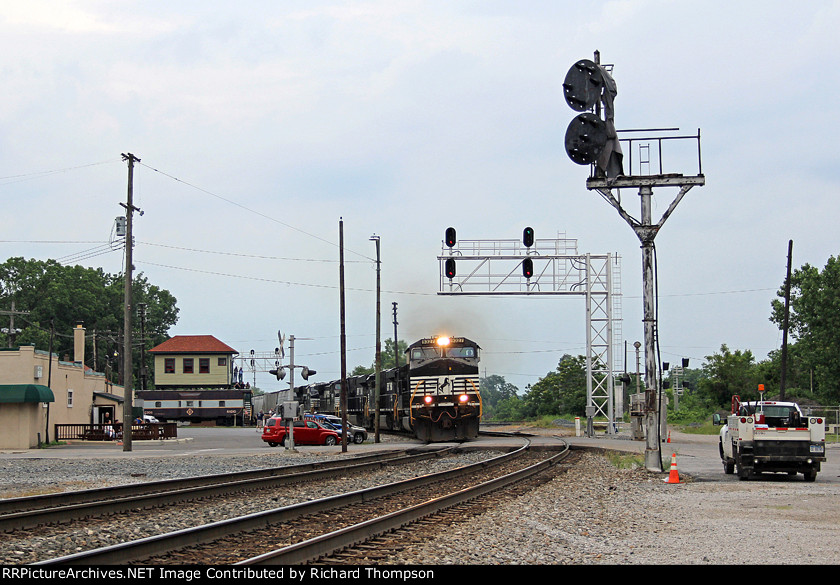
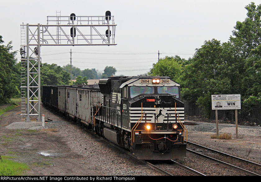
So lets take a look at Brighton Park as it was in its heyday before looking at what it eventually became. Before it was retired Brighton Park was known for its switchtender's shanty, 10 diamonds and that semaphore bracket. Back in the day however there was not one but
two primary tender shanties, four semaphore locations and and three additional tender shanties. Of all the manual crossings on the Panhandle trunk Brighton Park was easily the most complex in terms of the train control apparatus and this was mostly because this wasn't just a simple crossing like Ash Street, but actually had some switches that needed tending. These consisted of two western wye connections between the B&OCT and the Alton, a southeastern wye connection from the NYC to the Alton and a twin pair of facing crossovers between the Panhandle and the B&OCT. Operation of each of these crossovers was assigned to a specific switchtender with the Alton, PRR, B&O and NYC all employing tenders at Brighton Park to throw their assigned switches. The diagram above actually marks which switches were assigned to which tender.

Of course the mechanically operated semaphores at Brighton Park became its most iconic feature. At the time of its closure there were 8 signals still in operation, 5 on the central bracket mast and 3 on a secondary mast in the northwest corner of the crossing. These were directly operated from an 8 lever S&F mechanical frame via pipelines. The system was simple. When it was time for a train to proceed across the crossing the switchtender would raise the semaphore corresponding to the line and direction. The B&O, PRR, NYC and Alton each had 1 semaphore for each timetable direction for a total of 8. The B&O, Panhandle and Northbound Alton signals were mounted on the bracket, NYC and southbound Alton on the single mast. After Conrail abandoned the PRR Panhandle main line, a single ex-PRR running track was left in place for industrial work and it inherited the Panhandle semaphores. The lever frame provided basic mechanical locking to prevent conflicting movements from being routes (ie Alton xor anything else). Check out
Jon Roma's Flickr page for additional photos of the semaphores and pipeline system.
I mentioned before that the B&OCT had wye connections with the Alton. As you can see, with the Panhandle route standing in between the B&OCT and the Alton something had to be done. This came in the form of two additional semaphore signals which would protect the diamond crossings of each wye track with the Panhandle main line. The south wye was protected by an additional 4 semaphores worked from a 4 lever mechanical frame at the opposite end of the "A" tender Shanty. The north wye was protected by a similar set of 4 semaphores, this time worked by a miniature lever frame next to the mast outside of the "B" tender shanty.
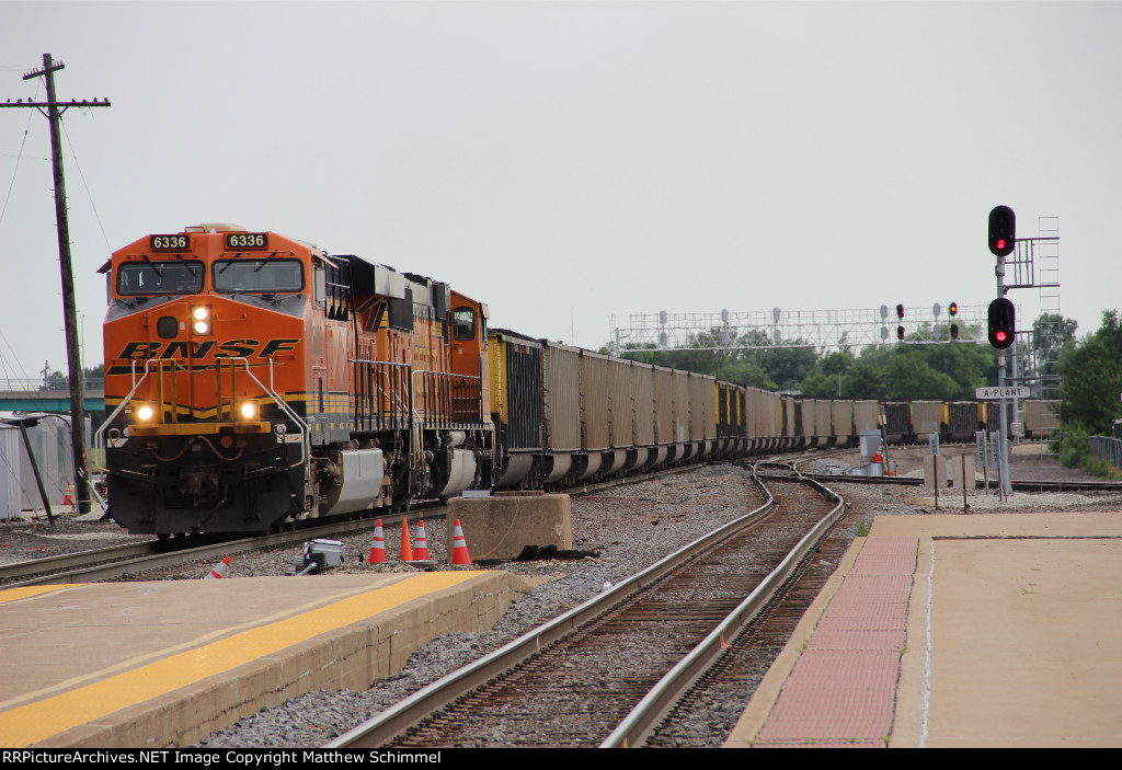
Since the 1940's and the resulting contraction of rail traffic, Brighton Park has been rationalized into the form we know it today. You can find a complete rundown of the current state of Brighton Park
on its own Chicago Rail Junctions page, but in summary, the former PRR Panhandle main line was completely ripped out leaving just the single industrial track behind with Conrail shifting traffic to the former New York Central line. The B&OCT dropped its wye connections to the Alton as that route decreased in importance and other interchange points became available. This reduced the number of diamonds to 10 in a 2x5 configuration. Without the wye tracks all the many switchtender positions and tender shanties were eliminated including the PRR "B" shanty and the two semaphore masts protecting the wye tracks. This left behind the "A" shanty and the 8 semaphore signals guarding the Alton crossing itself.

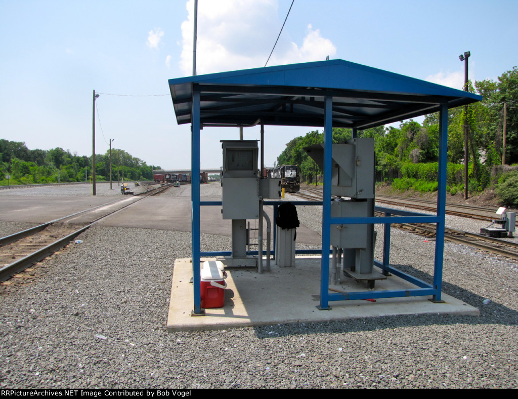
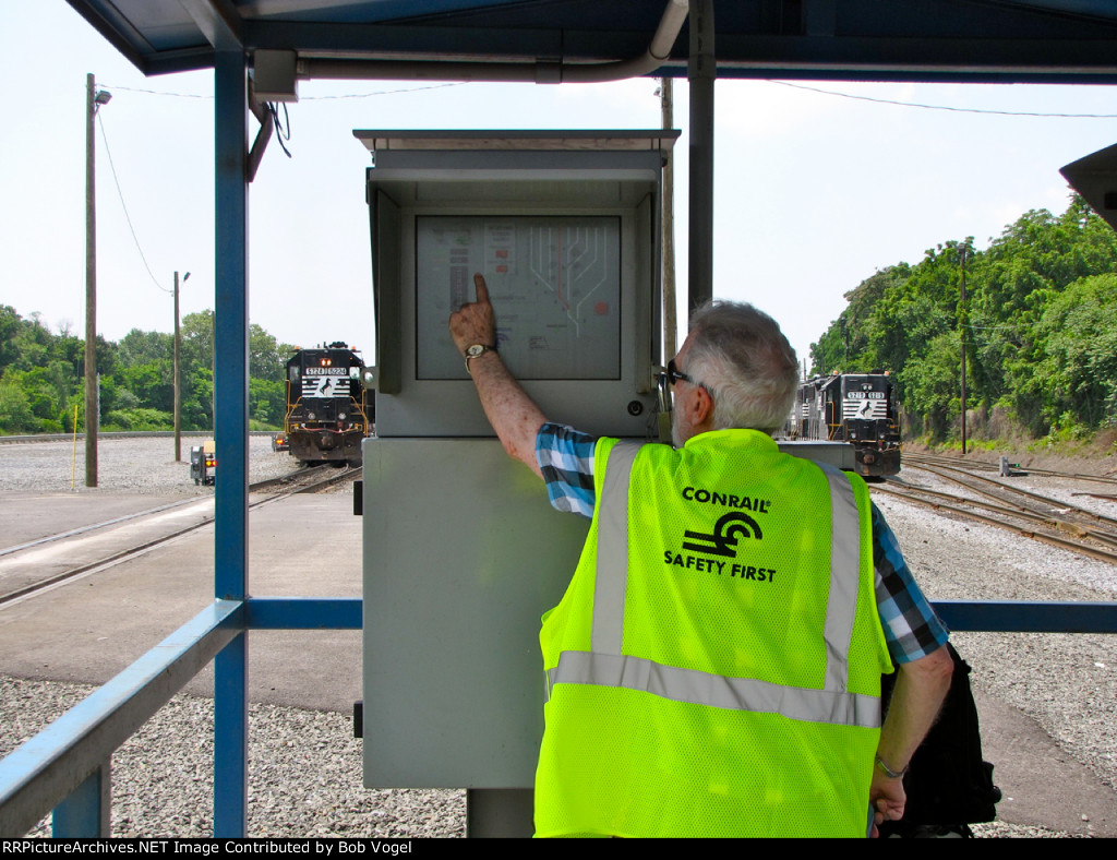
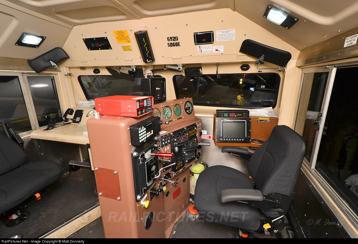
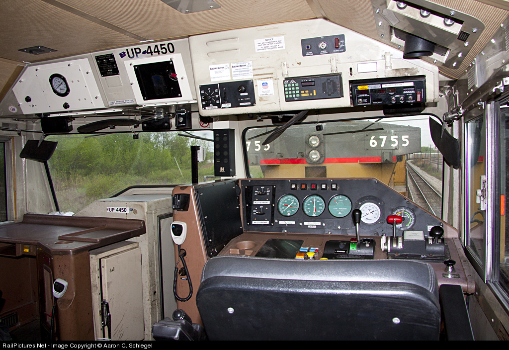
Like i said before Brighton Park isn't an interlocking and without the need to either house relays and electronics or keep them dry, the operating environment is rather minimalist. There is a door, some windows, an air conditioning unit and an external portable toilet. Even calling this a "cabin" would be generous and just about the only thing Brighton Park has in common with an interlocking tower is "Tower Window Syndrome". In this view you can see the pipelines emerging from the shanty's lever frame and passing through a set of cranks before running out to the two masts.


