OVERBROOK tower was built by the PRR in 1926 and was, chronologically, in the first wave of the all-brick style of towers that would become a trademark of the PRR in its later years. OVERBROOK was soon expanded in 1941 as part of a CTC project that gave the tower control over the remote interlockings VALLEY and JEFF (on the Schuylkill Valley Branch ), as well as having its own limits expanded with control over the west end of Belmont Yard installed as OVERBROOK's "Woodbine" section under direct wire control.

Still, compared to other PRR towers, OVERBROOK is notable for its rather diminutive size. Similar to later 1930's towers such as WINSLOW and YORK, it still presents itself as a bit smaller, especially compared to its sister towers elsewhere on the electrified main line.

The smaller size is more apparent in the quarter view where we can see that there is only one window on each of the sides, compared with two on the WINSLOW/YORK series of towers. One feature that reduced the footprint was the location of the air compressor plant outside the tower.

Despite its location in a big city, Amtrak was never hesitant to store spare signaling components such as PL signal targets and A-5 point machine covers, in the open, behind the tower.

Like most PRR towers, OVERBROOK is fitted with an internal staircase with a ground level entry. The money really shows with Flemish bond brickwork with a number of decorative courses. Also note the canopy over the door complete with slate shingles.

The PRR standard bay window takes up most of the width of the tower and today is outfitted with a number of VHF radio antennas. Also present is the interlocking horn, which is still functional and used to clear off people crossing the tracks in the station area.

A train order lamp, consisting of a single PL-2 unit, is still mounted on the east side of the tower. With 4 tracks and one bi-directional, there was less need for train order hooping at OVERBROOK, but it still took place from time to time. The 80's or 90's vintage Amtrak tower sign is clearly showing its years. Don't look for any further investment in tower aesthetics as efforts to re-signal the line loom.

Here is another view of the front of the tower, complete with a 9/11 flag, before the platform was rebuilt in 2003.

Opening the door we are immediately greeted by the sound of clockwork ticking and the smell of the 1940's as we walk right into OVERBROOK's relay room. Normally the relay room is locked and only accessible by C&S personel, however OVERBROOK is the rare exception where the operator can also poke about in the guts of the interlocking. In this particular bay of the relay room we can see older shelf relays off to the left and "newer" plug type relays on the right. Note the maintainer's chair, phone and stash of spare plug relays. This interlocking and tower is actually assigned its own full time maintainer, likely near retirement and the only person who knows how things works.

The shelf relays are attached to the 1926 portion of the interlocking, which basically means the 4-track crossover. Unfortunately I took these pictures back in 2003 when my camera card capacity was 96 photos, or I would have taken a lot more.


A quick examination of the labels on the plug relays indicate that they were installed in 1941 to control the direct wire Woodbine section. While that part of the plan was been reduced to a single switch and signal pair. Back in the day these relay banks supported 8 switches and 4 signal levers. It is likely that most of the plug relays are no longer active, but remain due to the cost of reconfiguration.

This photo of the rear of the first plug relay bay reveals why there is a full time employee dedicated to maintaining the plant. One has to admire the cable management. I doubt Google could do better.

In this wider shot of the rear plug relay board we can see the cable penetration in the ceiling for the signal wires to reach the Model 14 and CTC machines on the second floor. We can also see an additional set of shelf relays on the back wall.

Here is the lower half of the #4 relay panel, but more importantly this shows the location of the cab signal core generators and some spare US&S 504b code equipment.

These electro-mechanical cab signal code generators, create the 180ppm, 120ppm and 75ppm codes used by the PRR's cab signal system. These electro-mechanical devices have a tuned set of contacts that move back and forth at the appropriate rate, sending pulses of 100hz AC current into the rails. The interlocking plan has a single set of code generators whose signals are sent to the various track circuit end points where they are injected into the rails.

Control of the remote interlocking plants of VALLEY and JEFF was accomplished via the US&S 504b code system, that used sequences of DC pulses similar to a rotary dial phone system. These relay units would encode and decode the commands sent to and front the remote sites. State codes from the field would be reflected on the model board while changes to the unit levers on the interlocking machine would be send out as pulses.
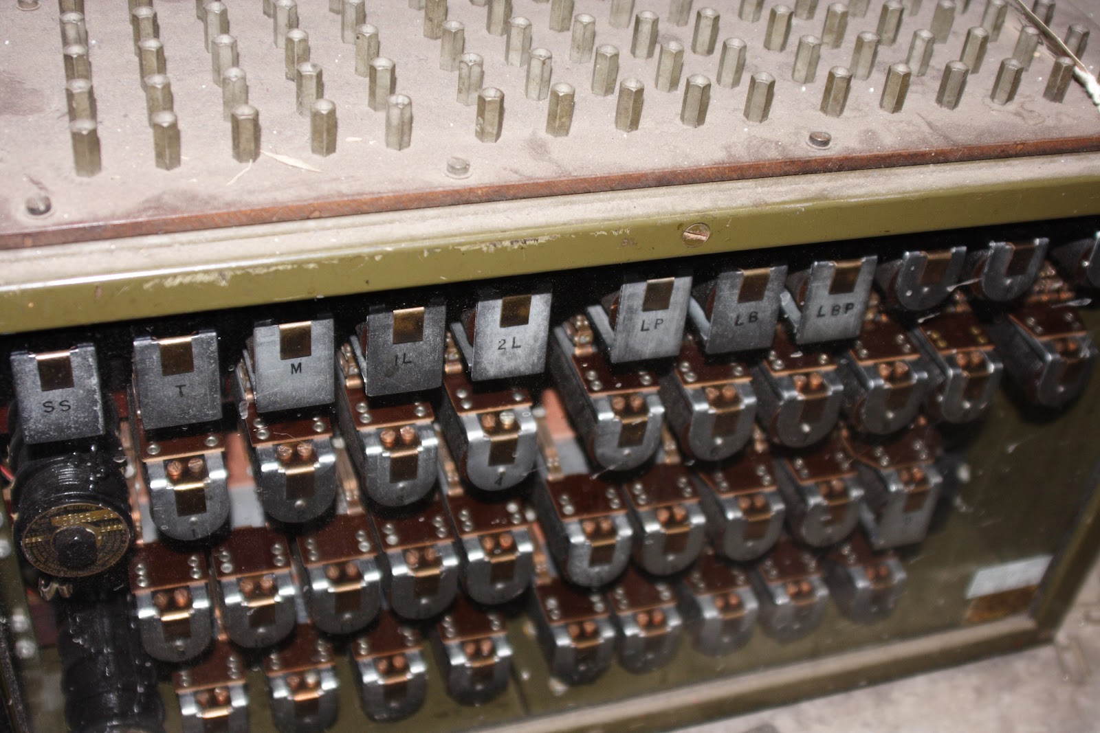

These 504b relay components are not hooked up and I assume they are spares. Note the telecom grade relay components compared to the railroad grade glass covered relays. Because the code system is not considered safety critical, the cheaper grade of relay is employed. Check out this video here for some additional information on the 504 code system.

Heading up the stairs into the operator's area we find the 19-lever USUS Model 14 interlocking machine sitting in the middle of the room with the operator sandwiched between it and the 1941 vintage CTC console. As I mentioned before, this dual machine setup is reflected on the tower diagraom on the interlocking chart. This is one of the smaller Model 14 machines I have explored and you can see it is only two inspection panels wide.

The machine has 17 levers with 19 spaces, lever spaces 2 and 3 being unused. 7 levers control 13 switches and 1 derail, 8 levers control 22 signals and two levers are for traffic control.

Here we see the two traffic levers, #1 and #5. #5 controls the bi-directional #3 track between OVERBROOK and BRYN MAWR. When BRYN MAWR tower was still in service, the operators of both towers would need to set their traffic levers in the same direction to set the direction. After BRYN MAWR burned down OVERBROOK's lever was given sole control of traffic on track 3. The #1 lever controls traffic on #1 track between VALLEY and OVERBROOK. The small button over the 1 lamp has to do with engaging the CTC system to affect the change. While from the signal diagram #1 track does not appear bi-directional, reverse moving trains receive Slow Clear on the opposite direction dwarf signals. Also, don't let the label fool you. The #4 lever controls the #3 track exit signal. This simplifies the interlocking in regards to the bi-directional track. It is the only "semi-automatic" signal in the 1926 plant and is usually left displayed for westward traffic.

Between levers 5 and 14 we can see the accumulation of 80 years of wear and tear on the levers. OVERBROOK is not some sleepy outpost as each rush period sees a flood of local and express trains all needing to be switched through the plant. Note the two blocking devices on the #7 switch lever, which leads to the dump siding on track #4. One can is for the rusty rail, the other is because the track was actually out of service at the time. The #8 and #10 signals are cleared for a westbound train on track #4.

On levers 13-19 we can see the #16 and #18 signals are cleared for the next eastbound movement on track #1. Note the small stops placed on the machine to prevent the reverse direction 16R or 18R signals from being displayed by mistake when restoring the two levers.

What from behind the machine looked like the model board, is actually the timer bank. In the 1930's, the US&S Model 14 was updated with integral, zone timers. Each bank of signal levers would have a timer mounted inside the machine that would be used to run them down in case a route needed to be canceled. Prior to this, and also in non-Model 14 plants, one or more glass globe timers would be provided elsewhere in the tower. Because the PRR was so well endowed financially, they took the extraordinary measure of supplying separate glass globe timers for EVERY signal lever. Here we see the timers for signals 4 through 10. Signals 4, 8 and 10 have a medium length release time of between 2 and 3 minutes. Signal 6 governs the dump siding and has a short release time of 1 minute. The release time is based on the line speed and the distance after the last signal so that an approaching train can be stopped before the route is changed. I am unsure what the knife-switch-like device (looks like a morse code key) is for. It could be the westbound train order light.

On the other side of the timer bank we find the 12, 14, 16 and 18 signal timers. These are long release with times between 4 and 5 minutes and control the signals on the tracks with ostensibly longer approach distances. It is notable that back in the day timers were each custom tailored to the signals they controlled. Today, most interlockings are fitted with a single 8-13 minute timer. Ouch! The thing is that all these costly timers are infrequently used because OVERBROOK and its Model 14 machine are equipped with approach locking, which allows signals to be canceled without running time as long as a train is not in the approach block. Once very common, this feature was removed outside of cab signal territory due to the race condition of a train passing a signal as it drops. On modern plants is almost never installed in North America leaving the few towers as the last refuse of its convenience.
Also visible here is another one of those strange mousetrap switches, the interlocking horn buttons for the east and west ends of the interlocking (only the west horn is still functional) and a tray full of blocking device cans.


Continuing on the theme of the PRR sparing no expense, OVERBROOK is also fitted with a panel blocking device. This was a convenience for the operator that relieved them of needing to apply the can type blocking devices to the levers and then re-applying them to accommodate various non-blocked routes that might use blocked levers. A panel blocking device provided dial switches on each single direction track out of the interlocking that, when turned would either block any route exiting via that track with the current of traffic or allow any route exiting via that track against the current of traffic. It's primary use was to protect reverse direction movements, since panel protection is not provided for bi-directional tracks, but it could also be used for any other situation where a track was out of service.

Well that's it for part 1. In part 2 we'll examine the CTC console and model board, the electric traction section breaker panel and all the other miscellaneous items in OVERBROOK's operating floor.
Thank you for this EXTENSIVE coverage of a relay room and the interlocking frame - I must definitely find some time to go through all the details ...
ReplyDeleteH.M.