
The solution was for railroads to become their own utilities and to string AC power lines on the pole line that was already carrying the telegraph and signal wires. The simplest (and most popular) form of this was a 440-480v twin wire setup running on the outer position of the lowest group of wires (where it was least likely to drop into low voltage DC C&S lines).

Of course one can't just plug medium voltage AC into low voltage DC relays and expect it to work. For this one needs a transformer and at every signal location along the line one was usually supplied on the pole to avoid bringing the 440 into the sensitive relay cabinets. The transformers aren't very big, and its easy to not even notice they are there. This example, on the B&O main line, likely dates from the 1950's or earlier. The 440v supply passes through two ceramic fuses so that the specific signal location can be isolated.

On the opposite end of the spectrum, here is a modern style signal power transformer supplied by the Olsun corporation in 2003. The AC-DC rectifiers are located in the relay cabinet or hut.

The next level of signal power supply involved a single or three AC feed in the kilovolt range. These were typically employed by wealthier eastern railroads with multi-track main lines and interlockings that could draw a lot of power. Of course higher voltages required larger transformers. Basically something on the order of what would be seen on residential utility poles. This retired three phase example was found on the N&W H-line running north out of Roanoke.

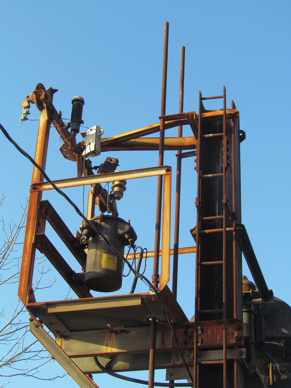
This active example was encountered at CP-SLOPE on the former PRR main line back in 2012. It had been installed before PCB's were banned in the 70's and has a big yellow sticker to that effect.
With transformers, frequency matters. The higher the frequency, the lower the inductive losses and the higher the equipment one can use. (This is why aircraft use 400hz power buses because they can use lighter transformers.) Mains power in North America is 60hz, however the Pennsylvania Railroad employed a 100hz cab signal carrier frequency to eliminate the risk of cross talk from 60Hz mains. This lead the PRR to actually adopt a 100Hz power supply in its electrified zone to eliminate the need for motor-generator frequency converters at every signal location. Here we can see a retired 6.9 kv transformer on the former PRR Port Road branch. You can see how the size compares with the 60hz transformers pictured above.
Here is a more contemporary example on Amtrak's NEC.

Today railroads are rapidly exiting from the utility business. It's a classic case of outsourcing. Now that public power utilities can be contracted to supply the power (even in rural locations), there is little reason for railroads to employ linemen and power engineers. Let the power company power and the railroad rail.
No comments:
Post a Comment