Found a couple of interesting photo sets on Flickr. The first are signal surveys of some N&W districts and the former C&O Buckingham Branch owned line from Gordon to Clifton Force.
http://www.flickr.com/photos/slip_plane_heart/sets/
The second is a signal and interlocking enthusiast's collection of Tower photos and I'll be damned if he doesn't have a photo of just about every currently and recently standing interlocking tower in the United Stated. Really worth a look.
http://www.flickr.com/photos/p3subhunter/sets/72157621068569864/with/5830899881/
Sunday, February 19, 2012
Friday, February 17, 2012
PHOTOS: THORN Interlocking
Before you think this is a duplicate post I should explain the previous post on THORN tower concerned the interlocking tower itself and the contents within. This post will focus on the THORN interlocking plant outside the tower. I had a lot of photos and some videos of the interlocking plant itself so I decided to split that off into a separate post. Also for those of you who care there are pictures of actual trains in this post instead of just interlocking equipment.
So once again I will be referring to this track diagram dating from 1992. Despite being almost 20 years old it is still an accurate reflection of the state of THORN interlocking.
https://www.redoveryellow.com/position-light/Amt_Diagrams/C-7.GIF
As I mentioned before in my previous post THORN interlocking proper was a 6-track full crossover located at MP 35.0 on the old PRR Main Line that originally consisted of 4 main line through tracks, 2 tracks of the Philadelphia and Trenton low grade freight line to the east and two tracks into Thorndale yard to the west. The last major change to the plant occurred when the P&T was reduced to a single track which changed the 53 switch from a crossover to a turnout. Since that time as the P&T and thorn yard were further abandoned the disused tracks were simply stubbed out to avoid costly changes to the interlocking plant.
In 2010 track #3 is a stub on both sides of the interlocking along with track 5 to the east. Track 6 to the west still has space to store MoW vehicles and #5 Running is also still in place. Track #2 to the east is out of service past the old P&T flyover, but the tracks are still in place.
To set the stage I will start us off with some video. Here is a rear facing view from an Eastbound Amtrak train traveling on track 1 through THORN interlocking. The video starts in the middle of thorn yard and continues through the interlocking, under the P&T flyover and then through the overhead power phase break that divided the Harrisburg power dispatch zone from the Philadelphia zone. Track #2 through between CALN and THORN through Thorn yard is active and is sometimes used as a pocket to hold SEPTA commuter trains or the odd local freight clear of the main. The train is traveling at about 90 mph and you can see the fairly new Thorndale station with its full length high level platform, the three track eastbound high signal gantry, the full 6-track crossover, MoW equipment stored on the #6 track stub, THORN tower itself, the silver painted air line for the 43 switch, the reverse direction position light "pot" signals, the P&T flyover and finally the Thorndale substation and phase break.
In the next video we have the opposite rear view from a westbound train traveling on Track #4. Here we see the removed #3 track, the abandoned P&T ramp to the flyover, the two track high signal gantry on #3 and #4 tracks, the mast mounted signal for the P&T, THORN tower and the air line, the reverse direction position light pot signals, the low level Thorndale platform, thorn yard ad finally what used to be CALN interlocking which is no longer in service on #4 track.
Tuesday, February 14, 2012
Active Tower Lost Then Found Then Lost For Good
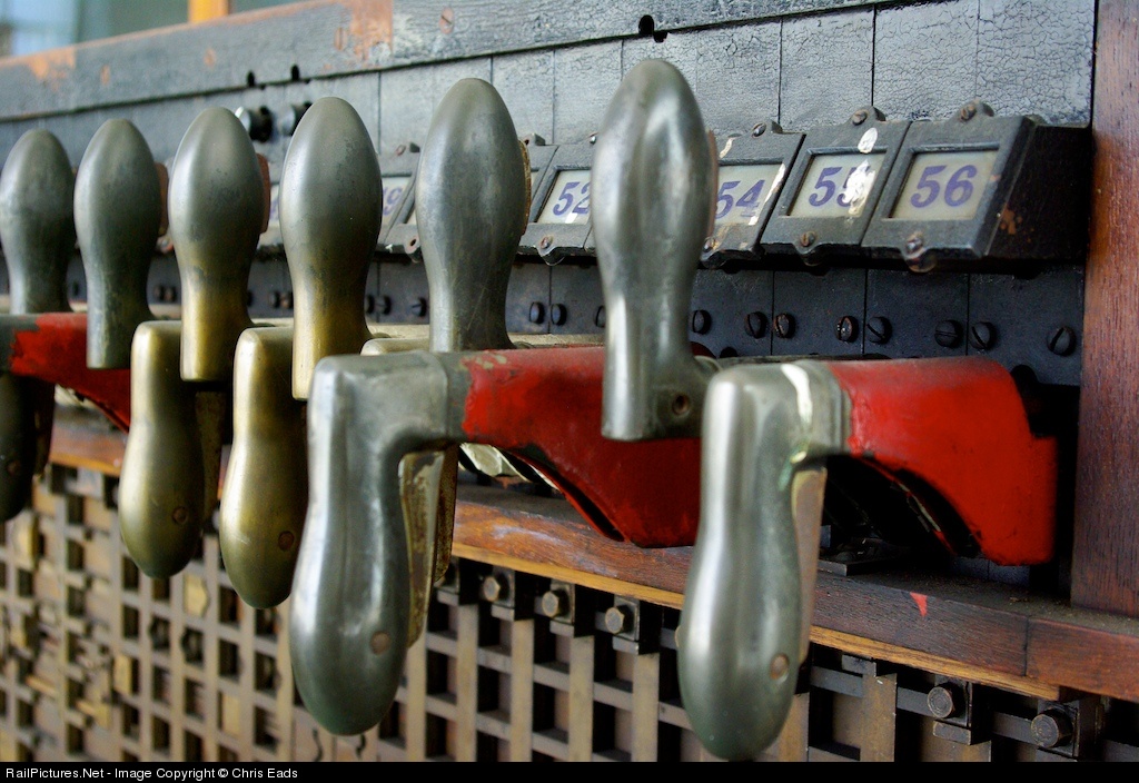
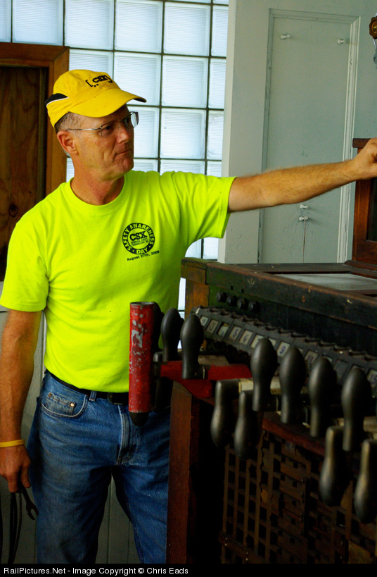
I just discovered an active tower previously unknown to the signaling community that has the glorious distinction of being active despite having closed over 20 years ago...and then after adding it to the active list, had to take it right back off again as it was closed for good in 2010 and DEMOLISHED in 2011. The tower in question is 'CA' tower in Terra Alta, WV on the famous CSX Mountain Sub, a all brick B&O design that is a sister to the famous SA tower at Sand Patch, PA (also demolished) and HX tower in Halethorpe, MD. Apparently, when the tower was first closed sometime in the 1980's due to a track rationalization, the line was still not put up for a re-signaling. As happened to a select few other towers, the maintainer chose to leave the interlocking machine in place, in this case a 56-lever GRS Model 2, and leave one lever wired up and active to run a single remaining B&O CPL automatic signal (previously a controlled signal in the interlocking plant). After, after 20 years in zombie service CSX finally got around to re-signaling that portion of the line, but also decided that as long as they had their backhoes in place they might as well demolished the secure and structurally sound tower. Way to preserve your heritage CSX, make sure that nobody might ever be in a position to preserve it. Let's hope that someone in the know was able to make off with the interlocking machine in some form.
Anyway, I was alerted to the ups and downs of CA tower by a pair of photos posted on railpictures.net.
Here we see the GRS pistol grip machine.

The single active lever equipped with a blocking device so nobody accidently causes a service disruption.

Anyway, I was alerted to the ups and downs of CA tower by a pair of photos posted on railpictures.net.
Here we see the GRS pistol grip machine.
The single active lever equipped with a blocking device so nobody accidently causes a service disruption.
Monday, February 13, 2012
Vintage Japanese Signalling Film
Now here is a little gem that proves the rule that sometimes the best way to learn about domestic history is to go abroad. This two part YouTube scan of a 1950's Japanese public information film on railway signaling starts off like you would expect, lots of lower quadrant semaphores and block instruments. However you will soon notice a US&S Style-S electro-mechanical lever frame...and then the entire second half of the film is dedicated to the operation of an electro-pneumatic plant operated by a rather impressive US&S Model 14 machine.
Now the entire film is in Japanese with no subtitles, but it really doesn't matter. The film is spot on showing action on the Model 14 and the corresponding action in the field. They get it all right, signal levers display signals and switch levers display switches. You can see in detail the exact way one goes about throwing a lever. Also on display is the Japanese system of Say-Point-Do (and sometime point again). Where the train director issues a command, the leverman repeated it, points at the lever to be operated, operates the lever, points at the change in indication then states the action is complete. The Japanese put American operators to shame (and its not the first time). Anyway, here are the videos and if you get bored the Model 14 machine stuff picks up immediately in the second part.
Now the entire film is in Japanese with no subtitles, but it really doesn't matter. The film is spot on showing action on the Model 14 and the corresponding action in the field. They get it all right, signal levers display signals and switch levers display switches. You can see in detail the exact way one goes about throwing a lever. Also on display is the Japanese system of Say-Point-Do (and sometime point again). Where the train director issues a command, the leverman repeated it, points at the lever to be operated, operates the lever, points at the change in indication then states the action is complete. The Japanese put American operators to shame (and its not the first time). Anyway, here are the videos and if you get bored the Model 14 machine stuff picks up immediately in the second part.
Tuesday, January 31, 2012
Now That's More Like It
What has continued to shock me in the current round of re-signaling is how much perfectly good hardware is simply scrapped for no apparent reason. Sometimes its as if the railroads just liking to be contrary, replacing bridges or cantilevers with masts, or masts with cantilevers and bridges. Often the old stuff is just a bucket of rust, other times it is barely 1 or 2 decades old with several more left in it. Well I noticed this little photo taken on a former ATSF main line where a classic ATSF steel beam signal gantry was outfitted with brand new Darth Vadar type heads. Yeah its not as nice as the original semaphores, but at least they made some use of the existing infrastructure.

Monday, January 30, 2012
PRR Main Line Survey 2010 Part 11 (STATE to CORK )
If you happened to enjoy my 10 part epic survey on the Pennsylvania Railroad Main Line between Philadelphia and Pittsburgh that just concluded I will be the first to admit that it was not exactly comprehensive as it was conducted in the westbound direction only. Last year I found myself in a position to at least partially rectify that situation by taking an eastbound journey on the Amtrak owned portion between Philadelphia and Harrisburg which had undergone some changes in the preceding year.
Anyway you can read most of the basic information about signaling on the old Main Line on the first part of the 2009 survey so I will hopefully be able to breeze through the 2010 inverse survey in a much more compact fashion. The quality of the photos is a bit more hit and miss due to the fact that I had to often shoot through two layers of glass and the weather was overcast. I know it doesn't work for some people, but you can always try the 1992 Amtrak diagrams starting at STATE interlocking as a line guide, although with the creeping re-signaling effort it is increasingly out of date. I will be drawing from the photos listed in this gallery which are in chronological order.
This segment of Part -1 will include Harrisburg to Lancaster, which was recently re-signaled.
Before we begin I have the opportunity to show off the Cab Signal Display Unit (CDU) that has been installed in most Amtrak locomotives and cab cars. The new CDUs work with the old PRR era pulse code cab signaling system (CSS) as well as the new ACSES track speed enforcement system which is still in limited service.
In this photo we can see a closeup of the new CDU with the cab signal indications being displayed via a miniature Amtrak type colourized position light over the signal speed digital readout. This is the speed determined by the CSS pulse codes, in this case 20mph for the Restricting cab signal (which is also displayed). Below the signal speed is the track speed, which would be determined by the ACSES system that is currently cut out as it is not installed anywhere on the Harrisburg Line. I think the orange LED bars under the speed readouts are some sort of countdown until there is a penalty brake application as the engineer has to both acknowledge any CSS drop, but also make a set brake reduction. The ACSES system only requires a specific braking rate, not a specific reduction.

Here is a wider view showing how the CDU is mounted in the cab of a Budd Metroliner cab car, just over the speedometer. Yes that is a GG-1 in the background. #4859 is on display at the Harrisburg Station to commemorate its honor of hauling the first electric train to Harrisburg in 1939.

Here is a video of the CDU freaking out after having been left on in the non-operating cab-car cab. When at Restricting the CDU demands periodic acknowledgment and this is what it does when it doesn't get it.
Alright, enough talk. It's time to begin our journey eastbound. Here the train has just left the Harrisburg station and has navigated the main part of STATE interlocking. Running from station track 7 to main track 1 the train makes a reverse move over the 101 switch. All points at STATE are pneumatic.

The 100L and 102L dwarf signals for westbound traffic into STATE. The main part of state is entirely Slow speed moves (15mph). Unfortunately due to some other states refusing high speed rail stimulus funds Amtrak was able to get additional monies to rebuild STATE interlocking over the next few years to eliminate the 15mph speed on at least the two main tracks. How this will affect the air operated points, the doubleslip switch and the Model 14 machine is not known at this time, but I expect it to be a job similar to CORK with a panel replacing the machine and all electric switches being employed (although STATE does flood every couple of years which gives air machines a slight advantage).

The 123 switch was original provided to allow trains on what was the freight only Columbia Branch (now the Norfolk Southern Royalton Branch) to access the Main Line. This branch ran parallel to the Main Line between here and ROY interlocking via the third track of the RoW so at least by the end of the PRR the Main Line between STATE and ROY was not 3 tracks, but one double track line and one single track line. In the 1992 diagram the connection via the 121 switch (marked as the F&G track) was still in place. In the original interlocking diagram you can see how it worked back in the day. Now only a shadow of the 121 switch remains and the 123 switch is rusty from disuse as it duplicates the function of the previous 101 switch. For a while it saw use for shunting movements pulling cars out of the express freight facility to the left, but Amtrak got out of that business in 2005.

The 120L is STATE's westbound home signal and one of the few high signals in the interlocking. This currently protects the 123 switch and acts as a distant for the 100L and 102L signals at the main section of the interlocking. As all moves in STATE ate slow speed the 120L tends to display / over ? for Approach Slow. It has a vestigial lower | for Medium Clear or Approach Medium for trains that were routed over the 121 switch on the F&G track.

This section of track between STATE and ROY was the first to be re-signaled under Rule 562, Cab Signals without fixed wayside signals. However Amtrak provided fixed wayside distants so that trains with failed cab signals could approach interlockings without preparing to stop. One of these are the 1015 signal for westbound movements approaching state. Both are new and of the Colourized Position type. The signal on the right displays the basic ABS aspects as the 120L at STATE lacks any diverging routes. The signal on the left can only display Stop and Proceed and Approach as the reverse direction 122L signal at STATE can only display slow speed indications. The signal on the right has a very diminutive numberplate that was installed by Amtrak under a previous refurbishment while new signal on the left has a new full size plate. On the far right is the 18W color light signal for the NS Royalton Branch. This is the distant signal to CP-CAPITOL.

Sunday, January 22, 2012
Great Northern Railway Signaling: Then and Now
The reason for this Then and Now post is because I recently completed a trip via Amtrak's Empire Builder that included a trip over the BNSF Senic Subdivision which includes, among other things, the famous Cascade Tunnel, longest in the United States. Along this trip I accounted for the "now" portion of the signaling by taking almost 400 photos from the rear of the train documenting almost the entire Subdivision except for a section around Everett where I had to go get dinner.
The "Then" portion of this post came up when I found a 4 part YouTube video series taken by a young boy whose father was a block operator for the Great Northern Railway in the period between 1957 and 1971. The 8mm home movies show mostly GN trains, but does pay a good deal of attention to signaling and train orders with some shots inside the Skykomish block station and a sound track that consists of dispatcher-to-train communications recorded on a reel-to-reel tape ,achine. The Skykomish office is shown at the very beginning of the second part and shows the 4-level table interlocking machine that controls the local siding as well as a CTC display board that at least reports train positions (a unit level panel was not shown).
What is today known as the Senic Subdivision exemplifies the model of a North American single track railroad. The Main Track is broken up by 1-2 mile long passing sidings, which today are controlled by CTC, but in that time were usually worked by the crews using hand throw switches and written Train Orders. The Cascade Tunnel was built in 1929 and until 1957 was worked by electric locomotives running in a special district between Skykomish and Wenatchee. Therefore the siding and yard at Skykomish were given the luxury of both power signaling and an on site train order station. Even after the electrification was replaced by a ventilation system for diesels, the Skykomish block station remained in service as it still had local and CTC control duties and the yard was still needed as a helper base. Also, the operator at Skykomish had the important task of controlling the ventilation fans in the tunnel.
Here are the links to the 4 videos (remember part 2 starts off with both "tower" footage and recorded "tower" audio).
My 2011 photos can be found here.
The photos covering the parts most frequently seen in the videos begin here and you can just keep clicking next. One interesting bit of signaling I wanted to cover was that of the Cascade Tunnel itself. The tunnel is 8 miles long, but since only one train can navigate the tunnel at a time due to ventilation constraints it functions as one long absolute block. Speed is only 25 mph so that combined with the need to vent the tunnel for up to 20 minutes after an eastbound passage makes the limiting capacity constraint on the line. The interesting bit is that to keep the air blowing in the right direction a door is closed on the fan plant end until just before the train exits the tunnel. The door is unable to be interlocked with the signaling system because it must open so close to when the train exits that there is might not be enough room for the train to stop should it fail to do so. For this reason a spare door is on hand in case the main door were to suffer a catastrophic failure. Such a failure has only happened once since 1957.
Here is a video taken from the rear of the Empire Builder in the final 1/4 mile of its transit of the tunnel as it passes through the fan plant and then out past the westbound absolute signal. The door opens about at the point where the video begins.
And here is another video showing the amount of time between the door opening and a train passing it (40 seconds).
Enjoy.
Subscribe to:
Posts (Atom)