A blog devoted to explaining the ins and outs of North American railroad signaling, past, present and future. This blog seeks to preserve through photo documentation the great diversity and technical ingenuity of 20th century signaling and interlocking hardware and technology. Related topics cover interlocking towers and railroad communications infrastructure.
Note, due to a web hosting failure some of the photos and links may be unavailable.
In my last RBMN signaling update from a speeder video in the winter of 2022, I noticed that turned signals had appeared in the last gap of dark territory on their Main Line between Hometown, PA and JIM THORPE JCT near Mach Chunk. Well as of the Iron Horse rambles of Summer 2024 the gap has closed ever so slightly with the ABS now ending at the turned Milepos 118S intermediate and the formerly turned 118N intermediate now being an active distant signal for JIM THORPE JCT. Although I didn't get a photo of the 118N, the 118S now bears the "END AUTO BLOCK" sign.
Apart from this I noticed no additional signaling changes on the former Conrail Lehigh Line, although I just now realized that the RBMN built a brand new interlocking on the Lehigh Line between CP-DUPONT and CP-LAUREL HILL in order to place out of service a portion of the second main track there.
The "new" SEIDEL interlocking uses the same 1980's GRS type three lamp housing color light signals that are also in place at CP-DUPONT and some nearby intermediates. Likely in place for well over a decade now, I had always assumed it was a Conrail era interlocking.
Electrically locked switches are the red headed stepchildren of the interlocking world. Not nearly as glamorous as their powered brethren, and rarely ensconced within the safe confined of interlocking limits, electrically locked switches help make North America's efficient bi-directional main tracks possible. For the uninitiated let me clarify that while powered points are also "locked" by something involving "electricity", when I say electrically locked switch, I am referring to a hand throw switch that has some sort of electro-mechanical interlock that prevents operation in the face of an unsafe condition.. E-locked switch hardware is provided by both major North American signaling lineages (US&S and GRS) and in today's post I am going to provide a quick overview of the broad e-locked switch families and how they work.
In the beginning if a railroad didn't want the expense of interlocking a switch with signals via a staffed tower their choices were to assume the risk of trains not being able to get stopped by an improperly set hand throw switch or ensure that all hand throw switches were in the trailing configuration, something that required at least two single direction main tracks. As track circuiting became the norm, operating a hand throw switch could shunt the circuit like any other obstruction, but this wouldn't be much help if an approaching train had already passed the previous block signal.
Unprotected hand throw switch equipped with a track circuit interrupter.
The easiest solution is procedural control where the employee shunts the track circuit, waits a proscribed period of time, then throws the switch. However where the railroad desires a bit more assurance than a padlock and watch, the electric switch lock comes into play. The concept is simple, use a solenoid mechanism to prevent switch operation until allowed by the signaling system. This can include direct dispatcher/operator control, like from a lever on an interlocking machine, or conditions such as track circuit occupancy or a rundown timer. In general direct control is the less common of the two as within interlocking limits railroads tend to just pay a bit more for power operated switch machines.
US&S TM-20 switch stand without an electric lock.
At this point I want to take the time to clear up a misconception regarding electrically locked switches. Above is the US&S TM-20 hand throw switch stand. It kind of looks like a miniature point machine with wires going into it, a mechanism to work a pipeline connected derail and an extra locking bar. For years I thought this was an electrically locked point machine because it appears on main lines that tend to benefit from electrically locked points. However there is nothing in a TM-20 that provides for locking functionality. The cover on the end is just houses an integrated make/break circuit controller. So while this type of switch stand might look the part, the real e-lock is a bolt on component.
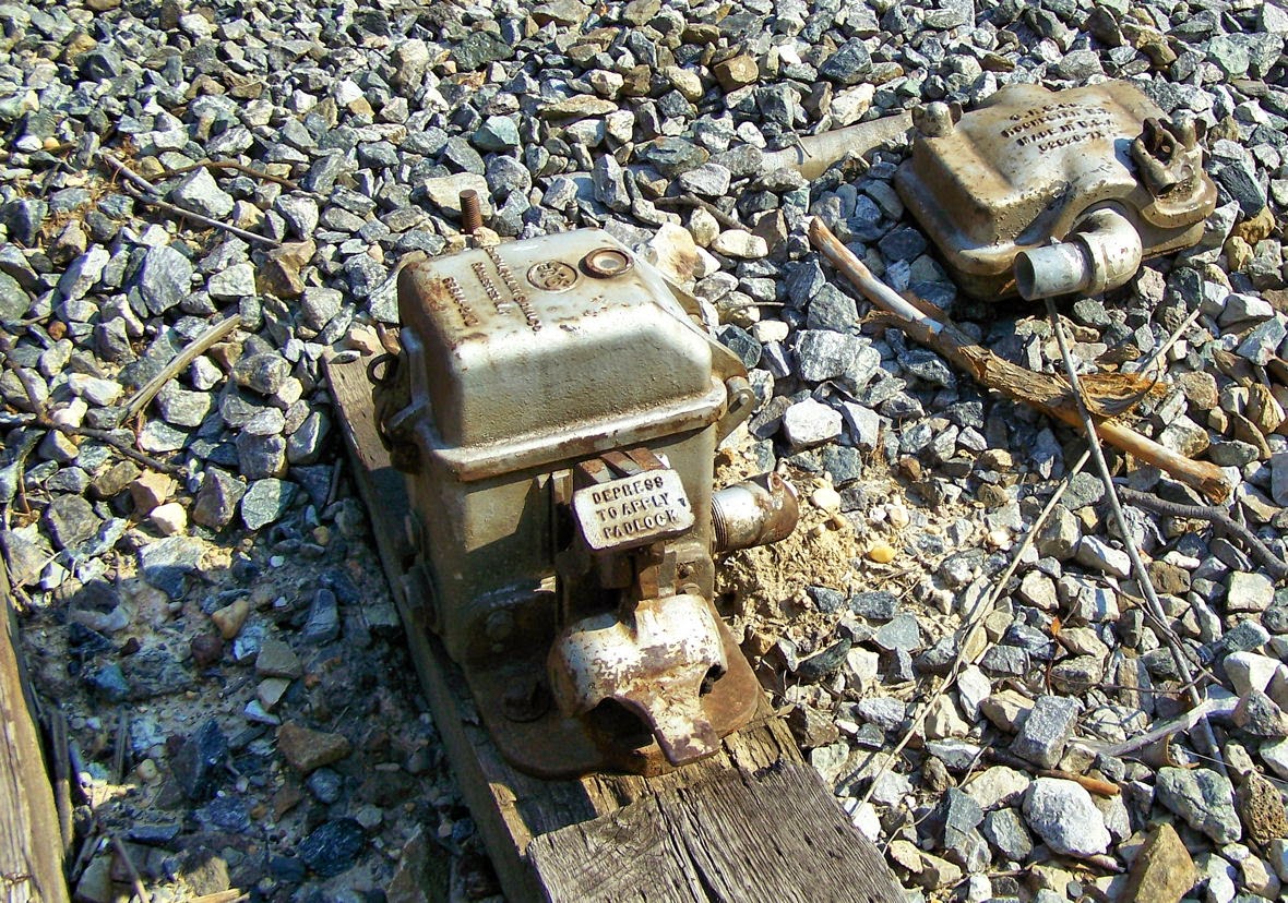
Abandoned GRS electric lock unit.
The E-Locks themselves come in two general forms, the plunger style and the pedal style. Each style is available from both vendor lines, but I want to discuss the pedal style first since it is the one paired with those TM-20 machines I just mentioned. The pedal style consists of a small box, separate from the hand throw point machine, which locks the hand throw switch arm in the desired position. The train crew's padlock holds down a small pedal. Removing the lock allowed the pedal to raise up, energizing the mechanism. In this state a small window displays either a green lamp if the switch is free to move or a red lamp if it is not. If a timer needs to be run, releasing the pedal starts it. Any timers and signaling relays are located in a trackside cabinet. When the lamp is green a second pedal can be depressed to unlatch the hand throw switch arm. Below is an example from the old CP-VO on the former Conrail Selkirk Branch where a direct control pedal type e-lock locks the throw arm of a basic dome type hand throw switch stand.
Interlocked e-lock hand throw switch stand within CP-VO.
Here we see a low profile US&S style lock device. Here we see a TM-20 with an SL-25 electric lock attached.
The SL-25 can be even located between the rails in a stand alone configuration and in this case uses a pipeline to lock two TM-20 point mechanisms on either end of an e-locked turnout.
Here we see the GRS answer to the TM-20 with an attached e-lock box. This example is located within the limits of CP-89 on the former Conrail Hudson Line and is released by a "lever" on the dispatcher's interface.
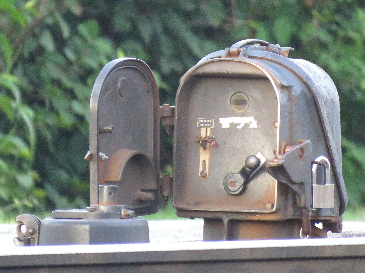
The plunger style is a bit more recognizable due to its more prominent form factor. The plunger lock consists of a little housing, sometimes on a raised pedestal, mounted adjacent to any type of hand throw switch stand. The trainman opens the little door and requests a release by moving a crank type lever from the lock to unlock-request position, similar to a US&S table interlocking machine. This engages the relays and timers in the cabinet and when conditions are safe, a solenoid releases and the crank is able to complete its travel, raising a metal plunger that is physically blocking movement of the switch point rodding in the process. The plunger is either directly below the housing or below the hollow pedestal, if present.
It is common to have both a short and long duration timer with short time (~30 seconds) applying when the main track is unoccupied and the long time (5-13min) applying when a main track train movement is possible. While short and long timers are not exclusive to the plunger type, the plunger type user interface makes them more apparent.
Another feature on the plunger type is the presence of a sealed emergency release button in case something goes wrong with the release logic. Breaking the seal and pressing the button allows for immediate release of the points. On the pedal type e-locks this functionality can be provided by an optional key switch.
Pedistal mounted plunger lock. Note the housing's similarity to a semaphore signal's.
These two types of e-locks are the bulk of what one will encounter in North America with the US&S and GRS equipment lines offering both form factors. It's actually pretty simple if you think about it, but if you don't want to take my word for it, here is a video from Mark Clay McGowan that describes the operation of each type in far more detail.
I hope you all found this interesting. I didn't get into the nitty gritty of identifying every exact model of lock, but now that you know what to look for, see if you can spot the slight differences out in the field.
A little while back I discussed the evolution of NORTH PHILADELPHIA interlocking from its construction in 1914 to its disestablishment in 2005. Early urban interlockings such as NORTH PHILADELPHIA were colorful characters with all sorts of extra infrastructure to handle not only the main line traffic, but also stuff like industrial switching, yard and light engine moves. FAIR tower in Trenton, NJ is not only NORTH PHILADELPHIA's sibling in appearance, but also in its arc through history. While I don't want to get too deep into the history and evolution of FAIR, I will say that it was drastically expanded in the 1930's, then entered a series of successive diets in the late PRR, Penn Central and Amtrak eras before the tower was closed around 1994.
In its second to last iteration that lasted from around 1990 to about 2020, FAIR had lost all of the double slips and freight support it had maintains up through the end of mineral traffic on the Belvidere and Delaware line. It's primary function was that of a passenger terminal for the Philly and New York area commuter services that terminated there. The two remaining quirky features were two additional tracks at the far northern and northerner limits of the right of way. Track 7 was used to store SEPTA equipment, while "North Low Track" served as an extra place to stash New York bound peak period trains overnight. Below you can see how the plant changes from its late PRR configuration to post CTEC configuration.
The area of interest is the North Low and Hill Tracks. The Hill Track used to connect with the Bordentown Secondary to Camden which saw limited passenger service like the famed Nelly Bly NYC to Atlantic City express train. In the commuter era that was used as precious storage space, keeping alive the old configuration that used to serve Doodlebugs that would run into Trenton from rural South Jersey.
While eastbound movements out of North Low could be made via the "Wall Track" past the tower, this involved a Restricted speed signal. The preferred option was the 86 switch protected by the 6BE and 8BE signals. This was located at the eastern end of the platform with 4 dwarf signals protecting the single low speed switch. One of the dwarfs was mounted on a striped stick for better visibility.
At the west end of the platform was another left-hand turnout, the 86W switch and associated 6BW and 8BW dwarf signals. You are seeing things right in this only allowed for North Low access from the hill track. This became an issue when around 2005 NJT opened up its Morrisville Yard west of Trenton in Pennsylvania, turning all of the terminal traffic that needed to be shuffled about into run-through traffic. Trains arriving from Morrisville could not access the North Low and as you can see from the rust, it became disused.
Starting in 2019, Amtrak brought the rationalization hammer down on this legacy configuration. The 86W switch was reversed, the Hill Track was removed and the 16 switch from Main Track 1 was fixed up for higher speeds. Now trains from Morrisville can access the North Low, making it potentially useful again. Unfortunately the next step came with the same interlocking refresh that removed all of FAIR's pneumatic point machines. The 86 switch and its associated signals were completely removed.
Trains using North Low will now have to take the slow route past FAIR tower and them on 0 Track to HAM interlocking, but as you can see from the grass, it is unlikely there will be a need for North Low any time soon. While this all makes sense, especially in the age where efficiency is more and more important, the 86 switch and its dwarf signals are still a loss worth noting.
Until recently Union Pacific operated one of the most extensive systems of cab signaled main line in North American, if not the most extensive (by route miles). Unfortunately as previously covered, the UP Automatic Cab Signal system was not immediately applicable to informing the required PTC overlay like Norfolk Southern's has proven to be, so the decision was made to take it out of service on at least the eastern portion of the network. However because so many UP locomotives were cab signal equipped and because in most situations the cab signal codes are still active in the rails themselves, UP has taken to covering over the cab signal display unit in the cabs.
I assume the same will be seen on many of the cab signal equipped CSX locomotives now that they have managed to rid themselves of the requirement on the centrally located RF&P Sub. It will be interesting to see how long this setup hangs around before the ACS display is completely removed.