A blog devoted to explaining the ins and outs of North American railroad signaling, past, present and future. This blog seeks to preserve through photo documentation the great diversity and technical ingenuity of 20th century signaling and interlocking hardware and technology. Related topics cover interlocking towers and railroad communications infrastructure.
Note, due to a web hosting failure some of the photos and links may be unavailable.
This blog devotes a lot of coverage to the plight of the pneumatic switch-point machine and its long decline since its heyday between 1930 and 1955, but apart from the ka-chug--woosh sound, what makes them distinctive? Well its actually their simplicity compared to their electric counterparts and its that simplicity that made them so competitive with electric point machines despite the overhead of making and distributing compressed air.
Above we see a Union Switch and Signal model A-5 pneumatic point machine. (An earlier A-1 model also existed and you can tell them in photos because the housing looks like a miniature Quonset hut.) At one end we see the double acting air piston, at the other we see a connection for the control circuits and a blind tube without an air piston, and in the middle we have a fairly plain looking box.
Next lets quickly go over a standard power operated switch layout using some casual terminology. Moving away from the camera we have a stretcher bar that provides rigidity. Next is the throw mechanism that transmits force from the point machine to the points via a rod. This uses a slack coupling so the point mechanism can begin to move and break the static friction. Finally we have the detection rods that accurately detect if the points are hard against the stock rail and communicate that state to the signaling system.
Exposed US&S A-5 pneumatic point machine.
The mechanism can be set up for operation from either side.
Here we see a naked A-5 without its cover on showing off the simplicity of the action. The air piston connects to an action bar which runs through a crank mechanism that transmits force to the point rodding and also its positional state to the circuit controller.
The crank (left) and circuit controller (right).
The coupling between the air piston and the action bar.
The air piston, these came in 3 inch and 5 inch diameter models.
The throw rod couples to the crank assembly. In the photo below this connection is the bolt hole on the stubby arm below the pivot pin. The detection rods sit under the circuit controller have the golden coated nuts on them.
The circuit controller pulls double duty, detecting both the position of the points for the signaling system and also the position of the action bar / air piston, which is sent to the style CP air value unit to cut the flow of air and dump the pressure in the piston. We can see the hind end of the action bar that is given room to push outward under the covering.
The upper two rods provide the actual point detection while I believe the lower rod that extends through the mechanism provides a physical locking function in conjunction with the action bar. When this technology was new that rod would serve the role of the familiar facing point lock.
The goal of the mechanism is to lock the switch point securely against the stock rail even when air pressure in the cylinder has been exhausted, but allow smooth movement of the action bar and points when air is admitted to move the piston. A similar concept is present in firearms where the bolt is locked against moving rearward by the force of gases in the chamber, but is able to be easily unlocked via motion in a different axis.
While I have personally captured video of an A-5 point machine performing a throw cycle, it only showed the points moving along with the admittedly cool sound. However I recently came across a different video from a UK rail museum that has their own flavor of a US&S A-series set up for live demonstrations. Still popular on the London Underground, these instances are commonly used without the protective cover which allows visitors to actually see how the mechanism functions. This flavor of Westinghouse point machine is intended to be set between the rails and has the throw rods moving through the mechanism. The extra circuit controller on the back provides feedback to the pneumatic value.
For those of you who don't know, "Mr. Beast" is one of the most popular figures on YouTube mostly appealing to 11-14 year old males with formulaic content that tends to involve giving away large amounts of money in novel ways. To get value from this post you do not need to know who Mr. Beast is and I am not recommending you view his content. In 2024-2025 Mr. Beast produced a 10 episode reality TV show for Amazon Prime titled "Beast Games". While watching an in depth third party review/breakdown of Beast Games, I noticed something in the 7th episode the pulled back the whole reality TV artifice a little farther than normal due to my knowledge of how railway signaling and operating rules actually work and I figured I should share it with the class.
The premise of the 7th episode, entitled "Elimination Train" was to set up a trolley problem scenario with full a size AAR locomotive and rolling stock on a Canadian short line. Chosen players would be placed on a surprisingly realistic fake signal bridge with a prop "lever" situated perpendicular to the track. They would then have to choose to direct the train either towards a high value vehicle they could win or representations of their team members facing elimination. (Note, this isn't a faithful representation of the trolley problem which tries to explore the morality of action vs inaction.) While the overall show suffered from a lack of play testing, they did manage to coax one of each outcome for this event.
Anyway this is where the fakery of reality TV becomes visible to anyone with rail knowledge. The sequence begins with the contestant "choosing" the car over the other contestants with the "lever" placed in the reverse position. However to keep up the drama its made clear that he can still change his mind at any time until the train passes the switch like in the conceptual trolley problem. As the full sized locomotive with one car in tow appears out of a smoke effect and approaches the switch the episode went into overdrive with rapid cuts, fast-mo, slow-mo and insert shots trying to build the suspense to see if the contestant will change the direction of switch.
However in every wide shot where the switch and the locomotive is visible, the points are shown to never move from their initial position, even if an insert shot shows the pints moving or the contestant moving the lever. The scenario is run more than once, in one the points are reverse and stay reverse and in the other they are set normal and stay normal. While this might fool the casual viewer, for the rail-informed watcher will know the fix is in once the locomotive appears and is moving faster than a jog, because there is no way in hell some shortline was going to allow the producers (and by extension the contestant) to actually solve the trolley problem and derail their locomotive. To the show's credit the switch mechanism was never shown in detail and the area around where a hand throw switch stand would be was intentionally hidden from view, however I am not sure how much this ultimately mattered for the viewers given the moving points were only shown in extreme close-up.
Here's what I believe went down in the actual production. First, while technically possible, its highly unlikely that a short line would have rigged up a power assist switch to the prop lever when a hidden grip could easily do the same job. The contestant was given some amount of time to make his choice while literal man behind a curtain followed the position of the lever and used the hand throw stand to align the switch points for the benefit of all involved. Then at some point, possibly even before the locomotive emerged from the smoke the choice was set and the train was allowed to do its thing. All of the drama was then manufactured in the editing room.
That's the irony of the situation. The show theoretically sets up a contestant the chance to solve the trolley problem, but doesn't have the balls (or insurance coverage) to actually allow the contestant to solve the trolley problem. What people don't get about the trolley problem is that the choices you are given aren't the only choices that exist. If one puts the points on center, the trolley derails and comes to safe stop. This is how split point derails work after all. (Conversely if you throw the points after the first truck passes over them, but before the second, you can get the trolley to drift and kill both sets of people tied to the tracks.) The real life trolley problem tries to set up a binary choice to explore an moral dilemma, however the mechanics of the problem allow folks with knowledge and the ability to think outside the box to make a choice where everybody lives. That's the important takeaway. If presented with a no-win scenario, you change the conditions of the test.
BTW, if you want to see how The Simpsons got an NYC Subway interlocking tower surprisingly right, check out this post here.
Electrically locked switches are the red headed stepchildren of the interlocking world. Not nearly as glamorous as their powered brethren, and rarely ensconced within the safe confined of interlocking limits, electrically locked switches help make North America's efficient bi-directional main tracks possible. For the uninitiated let me clarify that while powered points are also "locked" by something involving "electricity", when I say electrically locked switch, I am referring to a hand throw switch that has some sort of electro-mechanical interlock that prevents operation in the face of an unsafe condition.. E-locked switch hardware is provided by both major North American signaling lineages (US&S and GRS) and in today's post I am going to provide a quick overview of the broad e-locked switch families and how they work.
In the beginning if a railroad didn't want the expense of interlocking a switch with signals via a staffed tower their choices were to assume the risk of trains not being able to get stopped by an improperly set hand throw switch or ensure that all hand throw switches were in the trailing configuration, something that required at least two single direction main tracks. As track circuiting became the norm, operating a hand throw switch could shunt the circuit like any other obstruction, but this wouldn't be much help if an approaching train had already passed the previous block signal.
Unprotected hand throw switch equipped with a track circuit interrupter.
The easiest solution is procedural control where the employee shunts the track circuit, waits a proscribed period of time, then throws the switch. However where the railroad desires a bit more assurance than a padlock and watch, the electric switch lock comes into play. The concept is simple, use a solenoid mechanism to prevent switch operation until allowed by the signaling system. This can include direct dispatcher/operator control, like from a lever on an interlocking machine, or conditions such as track circuit occupancy or a rundown timer. In general direct control is the less common of the two as within interlocking limits railroads tend to just pay a bit more for power operated switch machines.
US&S TM-20 switch stand without an electric lock.
At this point I want to take the time to clear up a misconception regarding electrically locked switches. Above is the US&S TM-20 hand throw switch stand. It kind of looks like a miniature point machine with wires going into it, a mechanism to work a pipeline connected derail and an extra locking bar. For years I thought this was an electrically locked point machine because it appears on main lines that tend to benefit from electrically locked points. However there is nothing in a TM-20 that provides for locking functionality. The cover on the end is just houses an integrated make/break circuit controller. So while this type of switch stand might look the part, the real e-lock is a bolt on component.
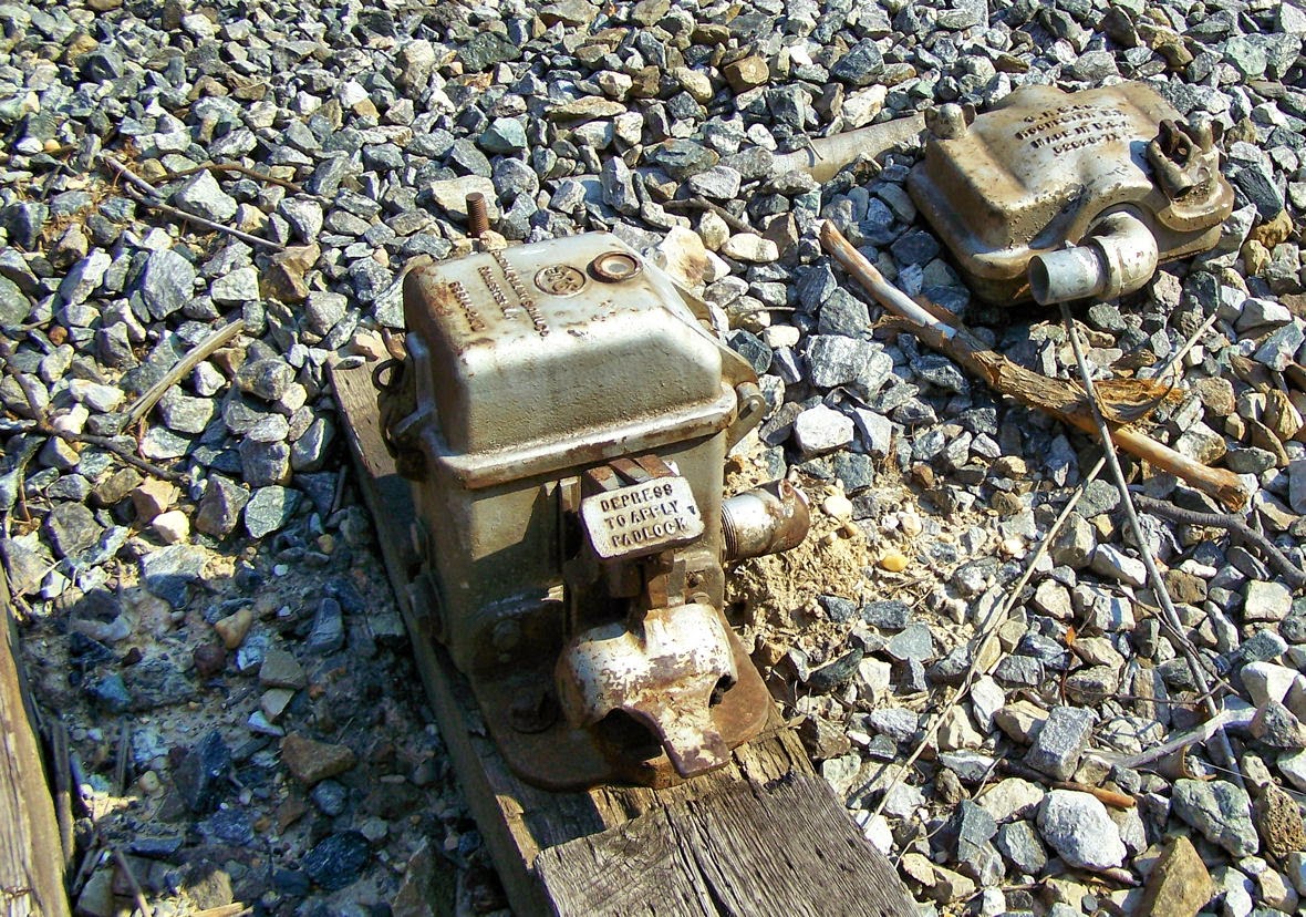
Abandoned GRS electric lock unit.
The E-Locks themselves come in two general forms, the plunger style and the pedal style. Each style is available from both vendor lines, but I want to discuss the pedal style first since it is the one paired with those TM-20 machines I just mentioned. The pedal style consists of a small box, separate from the hand throw point machine, which locks the hand throw switch arm in the desired position. The train crew's padlock holds down a small pedal. Removing the lock allowed the pedal to raise up, energizing the mechanism. In this state a small window displays either a green lamp if the switch is free to move or a red lamp if it is not. If a timer needs to be run, releasing the pedal starts it. Any timers and signaling relays are located in a trackside cabinet. When the lamp is green a second pedal can be depressed to unlatch the hand throw switch arm. Below is an example from the old CP-VO on the former Conrail Selkirk Branch where a direct control pedal type e-lock locks the throw arm of a basic dome type hand throw switch stand.
Interlocked e-lock hand throw switch stand within CP-VO.
Here we see a low profile US&S style lock device. Here we see a TM-20 with an SL-25 electric lock attached.
The SL-25 can be even located between the rails in a stand alone configuration and in this case uses a pipeline to lock two TM-20 point mechanisms on either end of an e-locked turnout.
Here we see the GRS answer to the TM-20 with an attached e-lock box. This example is located within the limits of CP-89 on the former Conrail Hudson Line and is released by a "lever" on the dispatcher's interface.
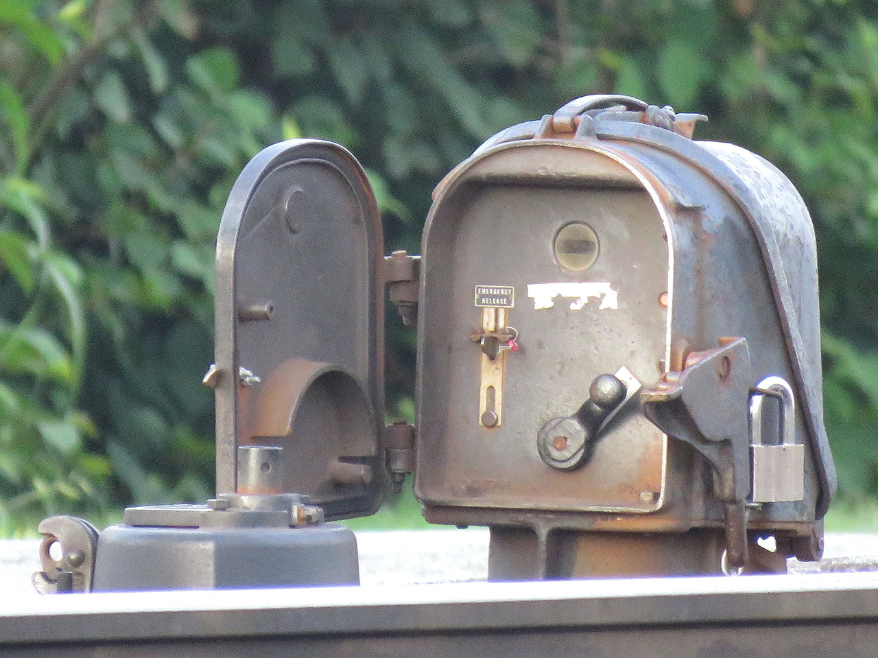
The plunger style is a bit more recognizable due to its more prominent form factor. The plunger lock consists of a little housing, sometimes on a raised pedestal, mounted adjacent to any type of hand throw switch stand. The trainman opens the little door and requests a release by moving a crank type lever from the lock to unlock-request position, similar to a US&S table interlocking machine. This engages the relays and timers in the cabinet and when conditions are safe, a solenoid releases and the crank is able to complete its travel, raising a metal plunger that is physically blocking movement of the switch point rodding in the process. The plunger is either directly below the housing or below the hollow pedestal, if present.
It is common to have both a short and long duration timer with short time (~30 seconds) applying when the main track is unoccupied and the long time (5-13min) applying when a main track train movement is possible. While short and long timers are not exclusive to the plunger type, the plunger type user interface makes them more apparent.
Another feature on the plunger type is the presence of a sealed emergency release button in case something goes wrong with the release logic. Breaking the seal and pressing the button allows for immediate release of the points. On the pedal type e-locks this functionality can be provided by an optional key switch.
Pedistal mounted plunger lock. Note the housing's similarity to a semaphore signal's.
These two types of e-locks are the bulk of what one will encounter in North America with the US&S and GRS equipment lines offering both form factors. It's actually pretty simple if you think about it, but if you don't want to take my word for it, here is a video from Mark Clay McGowan that describes the operation of each type in far more detail.
I hope you all found this interesting. I didn't get into the nitty gritty of identifying every exact model of lock, but now that you know what to look for, see if you can spot the slight differences out in the field.