Search This Blog

Showing posts with label interlocking machine. Show all posts

Friday, February 27, 2026

PHOTOS: LANDIS - The PRR Main Line's Forgotten "Tower"

One might wonder how the electrified PRR Main Line could have an interlocking tower somehow more "forgotten" than the small booth that occasionally managed the emergency crossovers at LEAMAN, but it did and that forgotten tower also began with the letter L. LANDIS tower, in Landisville, PA, was always a stepchild of an interlocking forced on the PRR by the rival Reading Company by means of the Reading and Columbia Branch.  This was a forked "milk run" line connecting Reading (via Sinking Spring) to Ephreta, Columbia and Lancaster. The Lancaster fork was ultimately integrated into the west end of CORK interlocking, crossing the main line via crossover switches and the Columbia Branch via diamonds. The Columbia fork met the PRR Main Line about 8 miles to the west at Landisville and, due to the lack of any existing infrastructure, the diamond managed to justify its own interlocking tower, built and operated by the PRR.

Given the telegraph code NV, a square wooden tower was built in 1902 in the contemporary PRR style exemplified by the preserved LEMO tower at Strausburg. 

This tower lasted into the post war period, its Victorian aesthetic somewhat in conflict with the electrification infrastructure. In this photo one can see the Reading alignment complete with Reading style US&S color light signals in a target configuration. Also note the Reading freight station which in this photo is partly obscuring the PRR Landisville freight station behind it. 

Based on the 1962 interlocking chart it can be surmised that the old NV tower was taken out of service around 1953 with the block and interlocking station moved into the old PRR freight house. Here the part-time operator would work the crossing as needed using a 5 lever US&S table type interlocking machine. Each main track had a pair of signals controlled by a single lever in the US&S fashion. The Reading was controlled by lever 1, the PRR levers 6 and 8. The Reading signals could display Stop, Clear and Restricting in both directions. The PRR signals had a full ABS head with a Stop and Proceed marker with the current of traffic and a dwarf with Restricting and Sop against. The Reading track had split point derails on either wide of the diamonds controlled by lever #4 and the PRR had a hand throw trailing point crossover unlocked by lever 5. The last detail of note was an 'E' marker on the eastbound PRR track which would illuminate if the dragging equipment detector near milepost 79 were activated.


As of 1954 LANDIS was listed in the timetable as an Interlocking Station open part time from 8:30 AM to 4:30 PM daily except Sundays and holidays. By 1971 this had changed to 10:00 AM to 6:00 PM Daily except Saturdays, Sundays and Holidays. Ultimately the Conrail merger of 1976 would prove fatal to the diamond crossing at LANDIS as the Reading branch line was no longer providing "competition" in the Lancaster market and Conrail trains based out of the PRR Lancaster yard could serve what on line customers remained. Therefore the diamonds were removed, the "tower" was closed, the milepost 74 ABS signals replaced the controlled signals on the PRR Main Line and a PRR freight delivery track was repurposed into a new connection to the ex-Reading branch towards Columbia, PA.


Like many legacy railroad structures along the Amtrak RoW, the freight station version of LANDIS was boarded up and left to become somebody else's problem. 50 years later the building still stands in decayed-yet-reasonable condition.


Similar to the Reading's old Chester Creek Drawbridge, the 5-lever US&S "table interlocking machine" is still present in the operator's area, albeit in a stripped down condition. Similar to the single story PARK tower, the windows were covered over with high security wire mesh.


The "table interlocking machine" was a modular platform for very small interlockings up to about 10 levers. Each module contained a standard US&S bell-crank type "lever" and was could interface with both mechanical and electro-magnetic interlocking components. At LANDIS the lever modules have been removed, but the robust metal base remains in place.


For comparison here is a similar table interlocking device set up in NORTH PHILADELPHIIA tower as an auxiliary to the main US&S EP machine. 
 

We can see that the LANDIS machine had a US&S/S&F style mechanical locking grid as well as make/break circuit spindles.


As an interlocking station the operator was provided with a full telecom suite mounted just outside of the bathroom nook.


An old relay hut sits across the tracks, although it is hard to tell what era it came from, Amtrak, PRR or PC.


LANDIS continued on as an ABS signal location until the mid-2000's Rule 562 re-signaling. Today only those with a knowledge of PRR Main Line history, or a sharp eye for abandoned rights of way, would notice that something had once gone on here.


Just goes to show that while many old towers have been demolished, a few are still hiding in plain sight.

Sunday, December 21, 2025

PHOTOS: LEAMAN - The Place To Be

The Pennsylvania Railroad Main Line, today operated by Amtrak as their Harrisburg Line, is known for its many interlocking towers that survived well into the 21st Century and I have covered several of them on this blog. However there is one "place" that isn't quite a tower, although it has many of the trappings of one. While the PRR seemed to have an aversion to CTC, it still had a lot more signaling infrastructure than peer railroads with a particular focus on Manual Block System and its related component, the block station. What's a block station? Well its a location on the line that can host a block operator who in turn can perform those duties necessary for some (manual) block operation like transmitting train orders, displaying signals and throwing hand operated switches. Even on signaled PRR main lines one could find non-interlocked block stations open either 24/7 or part time.

Located at milepost 56.7 between PARK and CORK interlockings on the Main Line is the town of of Leaman Place. You might recognize the name for being the interchange point for the Strasburg Railroad. This segment of the Main Line was electrified in 1939 and at the time  featured 4 main tracks. Despite the 24 mile gap between the two interlocking stations, no intermediate crossovers were provided as most disruptions could be dealt with by relying on the "spare" main track (with the parallel Columbia Branch directly providing an additional two tracks of relief capacity for freight). However in 1948 tracks 2 and 3 were removed due to declining traffic and evidently this length of single track operation during maintenance or equipment failure had become an issue because in 1961 the PRR constructed the new LEAMAN block station at milepost 57.0 with a pair of main track crossovers protected by semi-automatic signals. Unlike similar hand throw block stations LEAMAN had no normal hours of operation and was only open as needed for single track operation.


LEAMAN consisted of a pair of center locked hand operated crossovers and a pair of position light signals oriented in the normal direction of travel. As this was not an interlocking, no reverse direction signals were not installed. A rather robust operator's shelter was provided and outfitted with  station signs, climate control and telecommunications. 


This sort of hand operated crossover layout was not uncommon on other double track ABS main lines with the requisite "shelter" typically taking the form of a wayside telephone booth that would allow crews to call the dispatcher to pick up their movement authority to run through the single track area or to report clear of it. However LEAMAN was unique in that its signals and electric switch locks were tied to a small control panel inside the operator's shelter and not accessible to road crews. 

Sunday, October 19, 2025

Amtrak's Q and R Towers Close For Good

 Signaling control for the Pennsylvania Railroad's massive 1910 Penn Station project consisted of 10 block and interlocking stations. Towers N and S (later HUDSON) managed traffic at Manhattan Transfer, W (later PORTAL) handled the Hackensack River swing bridge, A, KN (B?), C and JO (D?) controlled Penn Station proper, F managed the eastern approaches and, R and Q controlled either end of Sunnyside Yard. N went first as Manhattan Transfer was consolidated into HUDSON interlocking in the early 1930's. PORTAL went next in 1988 followed by the four Penn Station towers and F being  replaced by the Penn Station Control Center in 1994. When HUDSON closed in 2003 it brought an end to the era of main line towers on the Pennsylvania Tunnel and Terminal railroad, but R and Q soldiered on at either end of Sunnyside Yard. 


In the early 2000's the 1910 R was re-signaled and the 1910 tower was demolished to make room for an Acela maintenance facility. Still, the complexity of the Sunnyside Yard operations still required the use of local operators, who were relocated into the yardmasters office in the Acela building to run the interlocking through a video interface. Around this time both Q and R were reclassified as "switching centers" to alleviate Amtrak of various regulatory requirements associated with main line interlockings. 


While the operator at R was playing video games in an office, Q kept going with its original US&S Electro-Pneumatic interlocking machine from 1910. Similar to the machine in ALTO and NORTH PHILADELPHIA, the Q machine was likely to be the last pre-Model 14 in active service in North America. Unfortunately, as early as 2015 one began to see the replacement of pneumatic A-5 point machines with electric M3's and by the early 2020's new relay cabinets were popping up all over. In 2024 I got word that the 1910 Q machine had been retired, the operator switched over to a video display like R, and just now I was sent these this Amtrak bulletin order taking both R and Q out of service and replacing them with the new Section S dispatcher in the PSCC.
 

Why this is happening now when long term closures of each of the four East River Tunnels are likely to complicate Sunnyside Yard operations is unknown. It could be that the Q re-signaling project was completed and found to be in working order and moving to PSCC was always part of the plan. Or it could be that Amtrak was having issues managing the two remote yard towers when everyone else except said towers were in the same room. If new productivity tools allow a single dispatcher to do the work of two or more operators (especially if they lack a clear view of the yard) remains to be seen.


Sunday, October 12, 2025

A Quick Look at WALBRIDGE Tower

WALBRIDGE was one of several active towers that ringed Toledo into the first decade of the 21st Century. Technically a PRR tower, WALBRIDGE stood at the triangular junction of the C&O Northern Branch, PRR Toledo Branch and the Toledo Terminal ring railroad. Like many PRR towers west of Pittsburgh, it lacked the fancy architecture and bay windows, and was instead a pretty basic brick box with a US&S Model 14 interlocking machine controlling a pneumatic interlocking plant with position lights in all the typical places. 


Like many of the survivor towers, it stayed in service due to the personal service needed to manage the trains of conflicting railroads, namely CSX and Conrail. After Conrail was broken up, it was pretty straightforward to rationalize the lines around Toledo, eliminate a lot of diamonds and close the towers. Anyway, Railroad Media Archives has posted another fantastic video from 1993 showing operations around WALBRIDGE including interior video as trains moved through the plant. You can cut to the exact time of the interior video or watch the whole thing. 

For some additional reference here is how the interlocking machine and model board looked in 2001.


Unfortunately the tower was demolished in 2015. If I ever find more than the handful of interior photos I'll write up a longer piece on it, but today just sit back and enjoy the video.  

Monday, June 30, 2025

MARION (AC) Tower's Missing CTC Machine

A couple years ago the folks at the Railroad Media Archive Youtube Channel posted a video covering the last months of Conrail's MARION (formerly AC) tower in Marion, OH.  Originally built by the Erie Railroad in 1902 and located at the parallel crossing of the CSX Toledo Sub and NS Sandusky Branch with the Conrail Indianapolis Line, the video shows off the tower's GRS/Taylor Model 2 interlocking machine with its proto-pistol grip type levers. At the time, MARION's operator only had control of the local interlocking, which seemed reasonable considering that they had to deal with train movements on separate railroads. However a new video from Railroad Media Archive shows a whole other side to operations at MARION. Sometime after the closure of the Eire main line around 1978, MARION gained CTC control of the Indianapolis Line between Belelfonte and Galleon (CP-BURT) with a 80's "Traffic Master"-style CTC panel and interface situated behind the operator's desk controlled by a compact interface of action keys and a numeric keypad.

In the posted video full attention is given to this CTC panel, with MARION's legendary lever frame barely making an appearance. We watch freight trains slowly cross MATION's territory while the operator discusses his duties and lines routes while text annotations appear in the video's side bars. It is mentioned that the tower would be losing its CTC territory by the end of the year (1989). 

The video captures that fleeting period between classic towers and train order offices, and modern point and click computer dispatch interfaces. By the time MARION was fully closed in 1995, all traces of its 1980's CTC territory had been removed. 

Saturday, May 10, 2025

The Enthusiasts Step Up

Unlike Europe, Heritage railroads in the United States never developed a vintage signaling component beyond what one might describe as display items. The big reason for this is that in service signaling and interlocking appliances have significant regulatory inspection, testing and documentation requirements that are beyond the reach of most tourist train operators. The result has been that most preserved towers are completely inert, with just a handful having interactive elements such as operable interlocking machines (SS43 BERK) or full on simulations (HARRIS). However, in recent years it seems that the private collector/enthusiast space has been stepping up to fill the gap as exemplified by the small YouTube channel Laser 711.

Signal and signaling equipment collectors have been around for some time, snapping up such items as model boards, CTC cabinets, full size signals and even interlocking machines. Until recently, railroad signaling departments would tend to keep their retired equipment, as similar vintage hardware was still broadly in service and the parts to maintain them were no longer being manufactured. However, the PTC related re-signaling push rapidly phased out so much of the relay era railroad signaling that the equipment is now being sold for scrap or offered free to anyone with the capacity to haul it away. 

In the context of interlocking towers, model boards and CTC cabinets have been widely collected for some time as switch to video display in a dispatch office had long ago destroyed their reuse value. Somewhat ironically, it was the older mechanical and electro-mechanical interlocking machines that retained the most value as a source of spares for their kin.  (For example a major reason LENOX tower near St. Louis was closed was to supply parts to the CNW LAKE ST machine in Chicago.) However as the number of these in service interlocking machines hit zero, anyone with a large enough truck could cart the survivors away for their own personal amusement. This is where Laser 711 comes in, having apparently set up not just a HARRIS style PLC backed simulation, but the full hardware stack including relays, point machines and signals.

 He has also restored an ex-Erie CTC console from BK tower along with its original code system, and now appears to be in the process of implementing as much field functionality as possible "in relay".

Of course it would be great if more publically accessible museums were able to step up to the plate with functional period correct signaling equipment, but the signal enthusiast community, powered by recent advances in the "maker" scene and high capacity pickup trucks, seem to be taking up a lot of the slack. Just like we have seen with the extensive telecom switch collection of Step by Step Phil, these private efforts stand a good chance of eventually finding their way into durable preservation.

Attempted CTC at the Seashore Trolley Museum

I will also mention that non-FRA regulated streetcar/transit museums have the best capacity to implement "live" historic signaling. When visiting Shoreline Trolley Museum I was shown their "in-progress" CTC system that they were building from thousands of relays donated by Amtrak and Metro North.


The fact that I have not heard much if anything about that project in the past 20 years hints at its priority in the greater scheme of things, but all it takes is the right team of enthusiasts to get a project off the ground.

Sunday, February 16, 2025

It's Electric! - The Westinghouse Brake and Signal Style L Frame

Every so often I mention the Westinghouse Brake and Saxby Signal Company which was the result of the British Commonwealth's Westinghouse Brake Company purchasing the then dominant UK railway signaling supplier Saxby and Farmer in 1901. For those of you who are unaware, George Westinghouse's claim to fame was the invention of the automatic railroad air brake and he set up corporate entities in both the US and overseas to market his produce. In an early example of corporate synergy, Westinghouse also became involved with railway signaling, either directly producing signaling hardware or owning a signaling subsidiary in many markets. Because there is little sense in reinventing the wheel, the Westinghouse corporate empire would cross-license signaling technology between its various arms. This is how US&S became the supplier of the Improved Saxby and Farmer type mechanical lever frame in the United States and how WB&SS Co would come to sell a power interlocking machine awfully similar to what would become the Model 14 family sold by US&S.

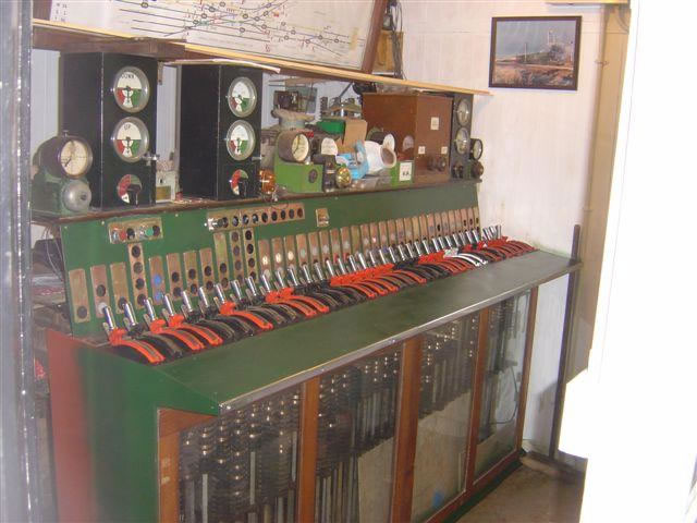
Balham Signalbox Style L Power Frame

As railway signaling moved from purely mechanical to incorporate automatic blocks, electric signals and power operated point machines, interlocking machines effectively became hybrids with both mechanical and electric locking. 19th century mechanical methods would continue to provide the route locking, while magnets and solenoids would lock the levers electrically based on track or switch position circuits. 

Electric locks on a traditional "armstrong" type lever frame.

Since safety critical railway signaling relays were quite expensive, signaling suppliers had an incentive to carry out as much logic as possible in the mechanical layer. Therefore even "power" interlocking machines like the GRS pistol grip style or US&S crank lever style still made use of miniaturized mechanical locking grids. 

Westinghouse owned Union Switch ad Signal had already been the North American licensee of the Improved Saxby and Farmer mechanical locking system and has been using it in its crank style power interlocking machines since the 1890's. In 1901 the newly minted Westinghouse Brake and Saxby Signal Company was suddenly in a position to employ US&S's innovations in Commonwealth countries and came out with its Styles A and B interlocking machines, localized for British signaling tastes.

WB&SS Co Miniature Lever Frame in British Service

Like the crank (ie "Model 14") style interlocking machines in North America, the Westinghouse power frames had three distinct logical components inside the box. First, a mechanical locking grid of the S&F type handling route locking. Second, locking magnets that would lock lever travel based on the state of the electric relay logic. Third, electric contact spindles that would make or brake electric circuits depending on the position of the lever. 

Style K frame with mechanical locking grid.

Style K frame contact spindles.

A route conflict would result in a hard lock as steel bits in the locking grid would physically block movement. An electric problem like points out of correspondence or an occupied track circuit would create a soft lock as the lever was stopped by magnetic latches interacting with a rocker arm on the lever spindle. Anyone who has visited HARRIS tower and its functional Model 14 knows the difference in feel between hard and soft.

Magnetic "soft" locks on a Model 14 machine.

All of this was fine until 1929 when the 23 ton weight of 311 lever London Bridge Style K interlocking machine made Westinghouse Brake and Signal question the sustainability of the technology. Unlike North American pattern machines, the British pattern was less lever efficient, needing more physical levers to carry out the same functions. This not only created a weight problem, but also a size problem as the locking grid dimensions grew literally by the square of the lever count. While American railroads had the space to build beefy towers with wide dimensions, the "early adopter" British railways had harder clearance constraints, especially in major cities where large power frames were most likely to be built. For example the aforementioned London Bridge signal box had to orient its locking bed vertically, making the tower an extra floor taller.


London Bridge Signalbox

The solution to this was the Style L frame. Externally the Style L looks exactly the same as the Style K, however internally it is quite different with the mechanical locking grid being completely done away with and replaced by electric locking. the Style L existed as yet another step between the purely mechanical interlockings of the 19th century and the all-relay plants that would ascend in the 1950's. However for anyone wondering why an electrically interlocked plant would even bother with clunky miniature levers, there are some advantages. First it maintains a familiar UI and reuses many of the components that were already in production. Second, it still reduces the number of high cost safety critical railroad relays. The latter is not entirely obvious, but an electro-magnet that unlock a contact spindle that a human then turns, is performing many of the same functions as a vital relay without the same need for precision manufacturing. The website covering Westinghouse power frames has both patent and part information so I'll leave digging down into the fine details of how this electric locking was carried out as an exercise to the reader. 
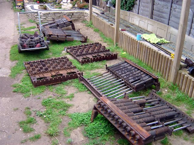
Style L parts

Style L restored

Style L relay locking logic

The Style L completely displaced the mechanically locked style B and K frames on the main line UK rail network with a burst of new deliveries being made to the British Rail Southern Region between 1948 and 1953. Additional frames were delivered to South Africa up until 1960 with a final BR frame delivered in 1962. An interesting ramification of the Style L all-electric logic was a far greater degree of adaptability than those with mechanical locking. In North America, all railroads (except naturally the PRR) had to hire US&S to perform major modifications to the mechanical locking grid. However the Style L electric locking could be modified without the need for specialized tools and British Rail was able to manufacture quite a few "new" Style L plants using left over components or even spare frames obtained for redundancy purposes during World War 2. Even after retirement from main line service, both heritage and miniature railways have been able to adapt surplus Style L equipment for their own track layouts.


The final act of the Westinghouse power frame would play out on London Transport in the form of the mechanically locked Style N and Style V frames as their modest lever counts and subterranean placement didn't trigger the same sort of weight issues seen on the main line railroads. In fact, the last Style V frame, think a Model 14 automated by pneumatic actuators) was installed on LT in 1993! (Which goes to show just how wedded the British were to mechanical technology.) With the closure of Wellington A Signalbox earlier in 2025 and Liverpool Lime St in 2018, the last active Style L outside of preservation might be the signalbox at Maidstone East, which was fittingly the last new built Style L delivered in 1962.