Search This Blog

Showing posts with label Reading. Show all posts

Saturday, December 7, 2024

Mind the Gap! - The case of "3rd Head Restricting"

There's a odd feature in current North American railroad signal practice dating back to the 19th century that hints at the practices of old like a vestigial organ. Lacking a former name, one might call the aspect "lowest head Restricting" or "3rd head Restricting", but its feature is a prominent gap between the top "full speed" or "normal route" head and the bottom lamp used to display Restricting indications. What would be a R/R/Y (or R/R/L) under normal circumstances, becomes R/ /Y, with the middle head omitted. So why does this exist and why is it still in use today.

Low head restricting originates in the concept of the subsidiary signal. In the days of mechanical semaphores a subsidiary signal is a smaller semaphore arm mounted below the "main" arms to give Restricting type movement authority.


In North America, it was not uncommon for this subsidiary signal to be mounted on the ground at the base of the mast or under the signal if mounted on a gantry or cantilever. The New Haven railroad was a proponent of this ground mounting practice and continued it up until they were folded into Penn Central.

As North American signaling progressed into the electric era, signal aspect systems would have an upper head for straight routes, a lower head for diverging routes and then a "subsidiary signal", either on the mast or on the ground, for Restricting/call-on conditions. Interlocking setups like the Taylor system would even have a separate lever controlling each signal head. Although this "third head" position on signals would later see use with other slow speed and combination indications like Medium Approach Medium, the link between the third head and Restricting remained strong. Of course as an economizing measure, some railroads went the route of only using two heads with R/Y as Restricting and simply not having a Diverging Approach type indication (its not strictly necessary). However, one could also economize by eliminating the middle head if it was only serving as a marker, especially if the lower "head" was its own signal on the actual ground. The Erie, along with the Reading, were both good examples of the gap between the upper and third head were left exceptionally large to avoid confusion.


Of course as signal mounting distances became more standardized, this gap became less emphasized to the point where one could make the argument that there was a likelihood of confusion between R/Y Diverging Approach and R/ /Y Restricting. Here we see an example of two bracket mounted signals with R/ /Y restricting at Chicago's KEDZIE interlocking installed by the CNW in the 1990's.


Today one can accommodate both R/Y Diverging Approach and a Restricting indication on a two headed mast through the use of lunar white or flashing red . At this time NS is the only major railroad to install new examples of R/ /Y Restricting and does so only on its former Southern RR signal territory. 


Of course quite a few railroads, including Canadian Pacific aligned Delaware and Hudson, never went with the economizing feature of the gap and instead went with a three head system with R/R/Y Restricting and R/Y/R Medium Approach. Under the Conrail associated NORAC system R/ /Y of predecessor roads like the Erie and Reading were considered to be a two head R/Y Restricting with three head R/R/Y Restricting as another option. The C&O on the other hand only had R/Y Restricting with any third head left dark because they just had to be different.

Friday, March 8, 2024

Reading Viaduct Signaling Remains

On November 6th, 1984 the last train departed the historic Reading Terminal in center city Philadelphia 4 days after the completion of the Center City Commuter Connection tunnel that allowed through running between the former Pennsylvania and Reading electrified commuter rail systems. Immediately after crews began to rip up the tracks as the tunnel had rendered both Reading Terminal and about 2 miles of elevated main line redundant. This also marked the end of RACE STREET as an active interlocking station and its task of signaling trains in and out of the 13 track station complex from the 4-track Reading Viaduct. Built in 1930 in conjunction of the Reading's own suburban electrification project to replace the previous interlocking from the 1890's, RACE STREET, or "RA" as it was known in the days of the telegraph, would fall to the wreckers ball as the viaduct between Arch and Vine streets was turned into a mix of event space and parking to support the new Pennsylvania Convention Center, that would also employ the Terminal train shed as an event space.

The surprisingly modern RACE STREET ("RA") tower at left.

While the demise of a historic terminal interlocking tower is nothing new, even finding a photos of RACE STREET was devilishly hard due to its position two blocks from the end of the passenger platforms and often located behind stored MU equipment. At 111 levers, RACE STREET's US&S Model 14 machine was as large as the one in HARRIS, but it features only 68 working levers, the same amount as the total number of levers in CORK. In addition to fanning 4 main line tracks into 13 station tracks, it also featured a junction with the single (originally three) track "City Branch" freight line and two storage pockets on the tower side of the terminal throat. The interlocking consisted of roughly 4 parts, each delineated complimentary signals. From north to south this was the outer set of medium speed crossovers, then the City Branch junction with a 3x4 double-slip field, the trailing point double slip ladder and then the final terminal fan. The terminal area made liberal use of Restricted speed routes with no signaled routes in the fan and only a select few in the trailing ladder. Of course this is all mostly academic as everything south of the City Branch junction was demolished  What about north of the junction?


Despite the demolition of both the tower and the core of its interlocking plant, significant artifacts of race street remain in roughly the condition they were left in 1984. This is because the main line viaduct north of Vine Street was abandoned in place as an electric power right of way to reach a rail power substation. While much of the track structure was removed, the overhead lines and their supporting gantries were needed to feed the electric power and attached to those gantries were RACE STREET's 1930 vintage color light signals. In 2012 the substation was replaced, ending active use of the viaduct for rail purposes, and the viaduct became an urban exploration hot spot with plans to eventually convert it into a High Line style linear park.


Working northward, the first surviving signal bridge is on the curve immediately adjacent to the Callowhill 25hz railroad power substation and features northbound high signals 20L and 18L for tracks 4 and 2, in addition to southbound high signals 28R and 26R for tracks 1 and 3.


The southbound 28R and 26R signals featured a full upper head, a middle head with green and red lamps and a Reading style horizontal head with the yellow Restricting lamp. The reason for the middle Green lamp without an accompanying yellow is somewhat unclear but I suspect that R/Y/R Medium Approach was unavailable in favor of R/R/Y Restricting. The only non-restricting signal south of here is on track #2  so both Approach Medium and Medium Clear would be possible.


For northbound trains the 18L and 20L signals are protecting medium speed main line crossovers. Track 4 had no diverging routed and was only supplied with a R/*/Y below the 20L full speed head while the 18L had two regular medium speed routes over the #17 and #15 switches. 


Both the 18L and 20: also feature metal ID tags on the back of the upper signal head. I'll also point out that all of the color light signal hardware is US&S style TR target (tri-light) with unitized lamp housings.


The next surviving gantry hosts the southbound 16R and 14R track 2 and 4 home signals and the southbound automatic track 3 and 1 exit signals. 


The 16R and 14R are mirrors of 20L and 18L except in this case the local track gets the diverging route over the #13 switch. 


The automatic exit signals are also nothing special, although the numbering system is a bit hard to figure out and apply to further automatic that are not on the diagram. It is also important to point out that tracks 1, 2 and 4 were bi-directional with the 16L signal able to display Slow Clear for straight movements, while the 14L on track #3 could only display Restricting.


A mere 800 feet down the line was the first automatic signal location with three northbound signals on tracks 1, 2 and 4, and southbound signals on all 4 tracks. The reason for the asymmetrical signaling was due to the presence of the Reading's MU storage yards on the east side of the line at North Broad. Deadhead moves heading to and from the yard would use track #4 in the shoulder peak.


Friday, October 8, 2021

PHOTOS: Inside LEBANON VALLEY JCT Tower

The Reading Railroad was small in size, but rich in revenue due to its dominant positions in the anthracite coal fields of eastern Pennsylvania. As such it was able to punch far above its weight in the area of technical investment be it electrification, locomotive manufacture or signaling technology. A very early adopter of automatic signaling in the late 19th century with the Hall disc signal, when the Reading was confronted with plummeting demand for their premium coal product, their response was technical innovation to cut costs and increase competitiveness. 

Once again the Reading turned to signaling and was an early adopter of the area interlocking concept that allowed for the closure of many manned interlocking stations, even in areas of high traffic density. Covered previously in my piece on North American Panel Towers, VALLEY JCT (officially LEBANON VALLEY JCT) tower was part of this technical overhaul that still stand to this day. Since I managed to come into possession of some interior photos I figured I might as well cover it in its own article. 


The VALLEY JCT we all know today appears in the form of a squat, 1 story brick cabin adjacent to the Lebanon Valley bridge over the Schuylkill River that today carries part of the NS Harrisburg Line between Philadelphia and Harrisburg. However if you look at it from another angle, it is actually a multi-story tower facing the Reading Belt Line that passes under the Lebanon Valley Branch at that point. In fact there is no interlocking on the Lebanon Valley Branch at Valley Junction. The interlocking is actually on the Belt Line, hence the name Lebanon Valley Jct (as the Lebanon Valley Branch doesn't junction with itself). The reason for this misconception is that the operator's floor is more accessible to rail photographers.


VALLEY JCT was built in 1951, towards the end of the standalone interlocking tower era in North America. It had direct wire control of the aforementioned VALLEY JCT on the Reading Belt Line as well as the nearby Wyomissing Jct and less nearby Klapperthal Jct (CP-TITUS) , Cumru, Tuplehocken Bridge (CP-TULP) and Belt Line Jct (CP-BELT). As CTC projects went this was not exactly pioneering, but was still a good 5-10 years ahead of the curve.


It's local interlocking under direct wire control consists of a simple crossover that allows Belt Line trains to choose a ramp to the Valley Branch at Wyomissing Jct or continue on to coal country and/or Allentown via Belt Jct.


VALLEY JCT was built with a General Railway Signal Style K unit lever machine with sequential numbering starting at CP-TITUS and increasing to CP-BELT. It eventually gained an independent panel to control WALL interlocking in Lebanon, PA in 1968.


VALLEY JCT's CTC territory was in service up until the late 90's/early 2000's when a combined Conrail/Norfolk Southern re-signaling project updated CP-BELT, CP-TULP, CP-WALL and CP-WYOMISSING JCT. CP-CUMRU would be re-signaled around 2010 with CP-TITUS surviving until 2018 as it was targeted for removal and replacement instead of reconstruction. The original 1951 relay hut is still in place at CP-WYOMISSING JCT, complete with its Reading Company herald. 


Saturday, June 26, 2021

PHOTOS: Reading DARBY CREEK DRAWBRIDGE

The Reading Darby Creek Drawbridge is located on a bit of industrial track that served industry along the Delaware River between Philadelphia and Chester, PA. Directly paralleled by a competing PRR line, much of the Reading branch and along the the Darby Creek bridge, were abandoned shortly after the formation of Conrail in 1976.


Nevertheless, movable bridges are substantial pieces of kit with non-trivial removal costs so for the last 45 years the remains of the Reading Darby Creek Bridge have sat in the weeds next to the PRR bridge, permanently open. 


It's easy to forget that movable bridges are almost all railroad interlockings, even on otherwise un-signaled territory. Moreover, this means that before CTC the person on hand to work the bridge would also need to work an interlocking machine and both Darby Creek bridges operated in this manner with the tender/operator managing both train movements and marine traffic.


In the case pf the Reading bridge, the interlocking was controlled through a US&S Electro-Mechanical machine with 2 active mechanical levers on a 4 lever frame and 5 active crank style levers on a 7 lever electric frame.


The combination of being manned for bridge openings, no need to associate with CTC territory and flying under the radar in remote locations has allowed for movable bridges to survive as active interlocking towers well beyond even their busiest main line peers. While the PRR bridge ultimately had its interlocking and bridge control hardware replaced in 2005, the Reading bridge, in a strange turn of fortune, unwittingly became a time capsule as Conrail literally turned out the lights on the old bridge in 1976 and walked away leaving the old interlocking cabin and interlocking machine mostly intact.


Placed in service some time around 1923, the Union Switch and Signal Electro + Mechanical interlocking machine used a combination of electric Model 14 style crank levers for electric based components such as the signals, and long mechanical "Armstrong" style levers for the mechanical components such as the bridge locks.


The mechanical levers, 5, 9 and 13, had only 5 and 9 functioning when the diagram was drawn in 1955 to operate the mechanical bridge locks with 5 operating the north lock and 9 the south.


As US&S had taken over the Saxby and Farmer style interlocking machine from the UK, this small frame still used the S&F style rocker action to interface the levers with the logic.


The electric portion of the machine has room for 7 crank style levers with 6 levers originally installed ad one of those being a spare. Three downward oriented levers, 4, 8 and 12, operated a total of 5 smashboard signals, while the upward oriented levers confirmed the position of the bridge locks (#6), worked the master bridge unlock (#10) and served as a spare (#2).


The rear of the machine exposes typical US&S style interlocking technology including magnetic coils for the quadrant style lever locks and electric contact spindles to interface the mechanical components with the various electric circuits.

Sunday, June 6, 2021

PHOTOS: Inside SEPTA's Last Towers

Over the last 20 years North America has seen the virtual extinction of "Paper Dispatching", the practice of railroad dispatchers being totally reliant on field tower operators as their eyes and ears. Operators report movements to dispatchers, dispatchers mark down train progress and inform the operators of any necessary changes. Depending on the railroad the dispatchers and operators may have more or less authority and in others the while two level hierarchy may not exist at all. Anyway, in this time period there has only been one rail system that I am aware of that went from Tower controlled to Dispatcher controlled in one fell swoop and that would be Philadelphia's commuter railroad SEPTA. 


Founded as an umbrella funding organization in the 1960's, for its first decade and a half SEPTA contracted with the legacy carriers Penn Central and Reading and later the government supported Conrail that emerged from the bankruptcies of both predecessors, to provide service on the Pennsylvania and Reading Railroad's vintage electrified suburban districts. The PRR side of the house was generally worked on the interlocking tower system with single towers controlling one or a few adjacent interlockings. The Reading on the other hand developed a taste for CTC schemes controlled by panels within existing towers. In the mid-1980's a series of events would combine to create SEPTA's unique tower culture. First, Conrail was forced to pull out of contract suburban operation in favor of direct operation by SEPTA. Second, SEPTA completed construction of the Center City Commuter Tunnel that linked the PRR and Reading networks, eliminating the stub terminals and third, SEPTA built the brand new Airport Line along with a number of "state of good repair" projects like the rebuilding of the Reading trunk line and improvements to the West Chester and Chestnut Hill West lines.

The result was that all of SEPTA's rails were controlled from 7 interlocking towers. The first two, WIND and WAYNE, were co-located within the old Reading WAYNE tower building at Wayne Jct and consisted of two 1960's vintage CTC panels that not only controlled practically all of the Reading suburban network, but also parts of Conrail freight lines due to the shared Reading System heritage. The next two, BROAD and MARK, were built as part of the Commuter Tunnel Project and replaced two large Model 14 legacy terminal plants with modern N-X panels. The next two, MEDIA and CHESTNUT HILL (WEST), were direct PRR legacy towers that controlled terminal operations on the West Chester and Chestnut Hill West lines with their original interlocking equipment. Finally A TOWER was constructed new in 1985 to control the Airport Line with a contemporary unit level panel.


Beginning our tour at 
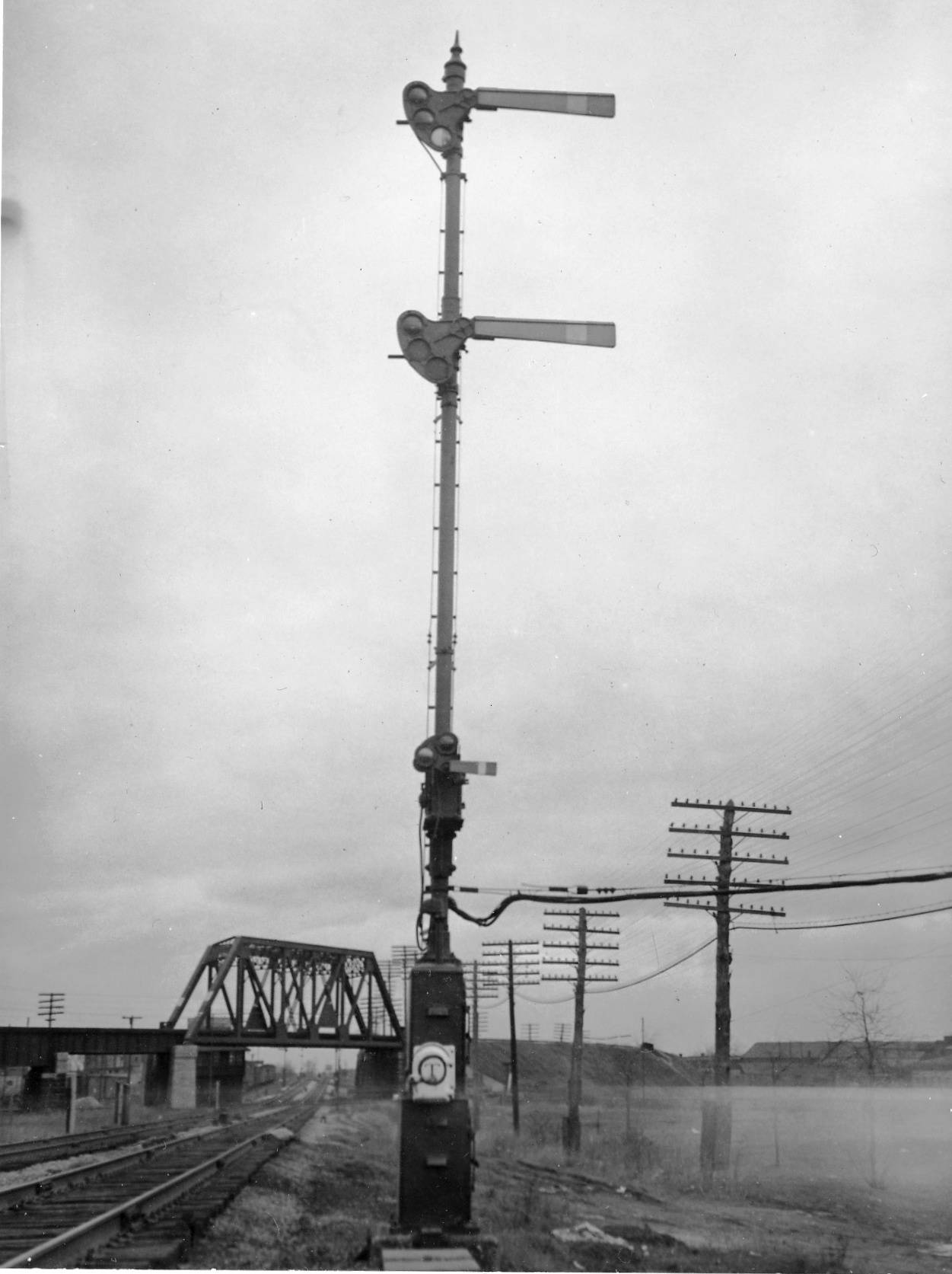
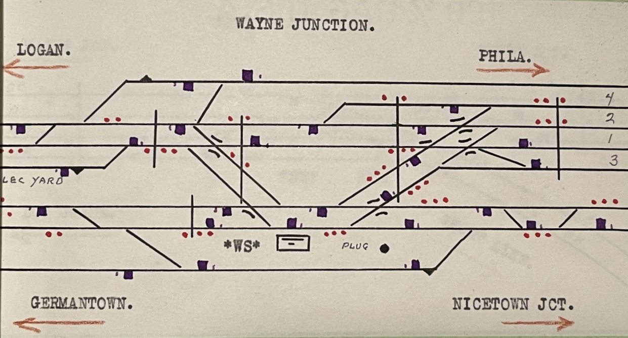
Wayne Junction, WAYNE tower was the most traditional of SEPTA's diverse rail control locations being located inside the former Reading WS tower, a 1920's era Model 14 powered facility that controlled the 
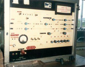
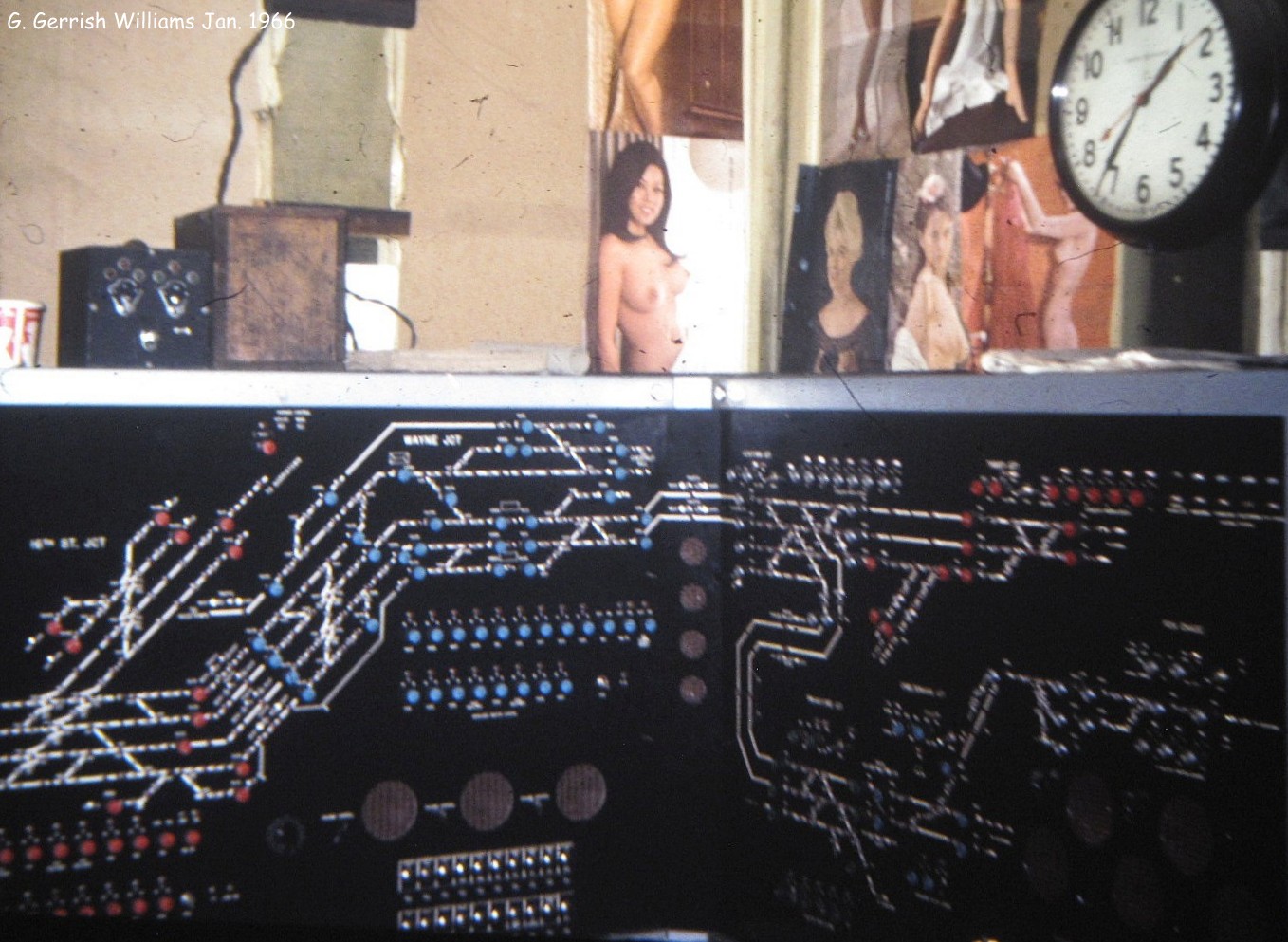
double junction between the New York/Bethlehem main line, Chestnut Hill East branch and Tabor Branch freight link. Unlike the PRR, the Reading wasn't afraid of new technology and in 1965 it implemented a wide-scale CTC project that consolidated control of its Suburban network inside WS/WAYNE tower. (Note, by CTC I mean remote interlocking control as there was only a limited amount of actual Rule 261/CTC operation in this territory.) In the tower the old Model 14 machine was supplanted by two high end General Railway Signal NX panels installed in adjacent corners of the operator's floor.

Operator lines a route at 16TH ST JCT on the WAYNE panel in 1991.

Other half of the WAYNE panel in 1991.

This gave rise to WAYNE Towers's unique "Two Towers in One" layout with the "WAYNE" panel and operator controlling everything between 16TH ST JUNCTION at the top of the Viaduct to TABOR JCT (Fern Rock) on the Main Line and the Fox Chase branch (via Newtown Jct and Cheltenham Jct). The WAYNE panel saw one major alteration with the "south" end of the panel being extended to accommodate the insertion of the new HUNT interlocking and reconfiguration of WAYNE interlocking to support the mid-80's opening of Robert's Yard. Compare the above and below photos to the original 1965 configuration (NSFW).


South end of the WAYNE panel in 1994

North end of the WAYNE panel in 1994

The second panel and its operator was known as WIND and was interesting for not only being a virtual tower located about 6 feet away from the WAYNE panel, but also not actually controlling an interlocking named WIND. WIND's territory was everything north of Tabor Junction including the R5 route from Jenkintown to Doylestown, the R2 to Warminster, the old New York Branch/R3 to Woodbourne and even the previously signaled Stony Creek Branch to Norristown. WIND also had control of the New York Short Line that would become the Conrail Trenton Line north of Cheltenham Jct which included a single controlled siding and various joint interlockings between Neshaminy Jct and Woodbourne. 

WIND panel 1991 with WOOD interlocking and Fairless Branch.

Between 1991 and 1993 the first state of the Conrail SEPTAration began with a re-signaling and track re-alignment project on the Trenton Line transferring control of Conrail trains between CP-CHELTENHAM JCT and CP-WOOD (exclusive) to the Conrail dispatcher. You can see in the following 1994 photo of WIND how the north end of the old New York Branch has been deleted off the panel as an active element. 

WIND panel in 1994 w/ WOOD interlocking etc blanked out.

SEPTA's WIND would retain control of both CP-WOOD and gain control of CP-TRENT after TRENT tower's closure in 1994. Unfortunately my photos do not reveal the method of control, but it would most likely be a computer terminal seeing as how CP-WOOD and CP-TRENT was re-signaled to 90's Conrail standards. The only remaining portion of the Reading Suburban network I have yet to cover is the Norristown terminal area that was originally controlled from a CTC panel in NORRIS tower. NORRIS tower closed some time after 1988 and by 1994 the CTC panel had appeared in WAYNE tower (likely under purview of the WAYNE operator). A 1991 photo shows a non-operable mimic board installed in the tower which may have operated to inform the WAYNE operator of R6 terminal movements before NORRIS closed. 

1991 Norristown area minic board.


1994 Norristown area CTC panel.

If you were wondering how two operators could handle all the train movements on the Reading side of the SEPTA network on an NX panel without any form of automated train labeling, I was told that at peak times each "tower' each would support at least two panel operators working in a non-socially distanced manner. Based on the recollections of a visitor, it was also likely that the physical WAYNE tower operation included a train director to call some routes and handle communications with the SEPTA dispatchers. By the turn of the 21st century SEPTA WIND and WAYNE had a very distinct presence on the scanner scene with their VHF transmissions registering loud and clear at least 10 miles distant in South Jersey. It was a truly modern rail dispatching operation in all but name.

MARK tower panel.

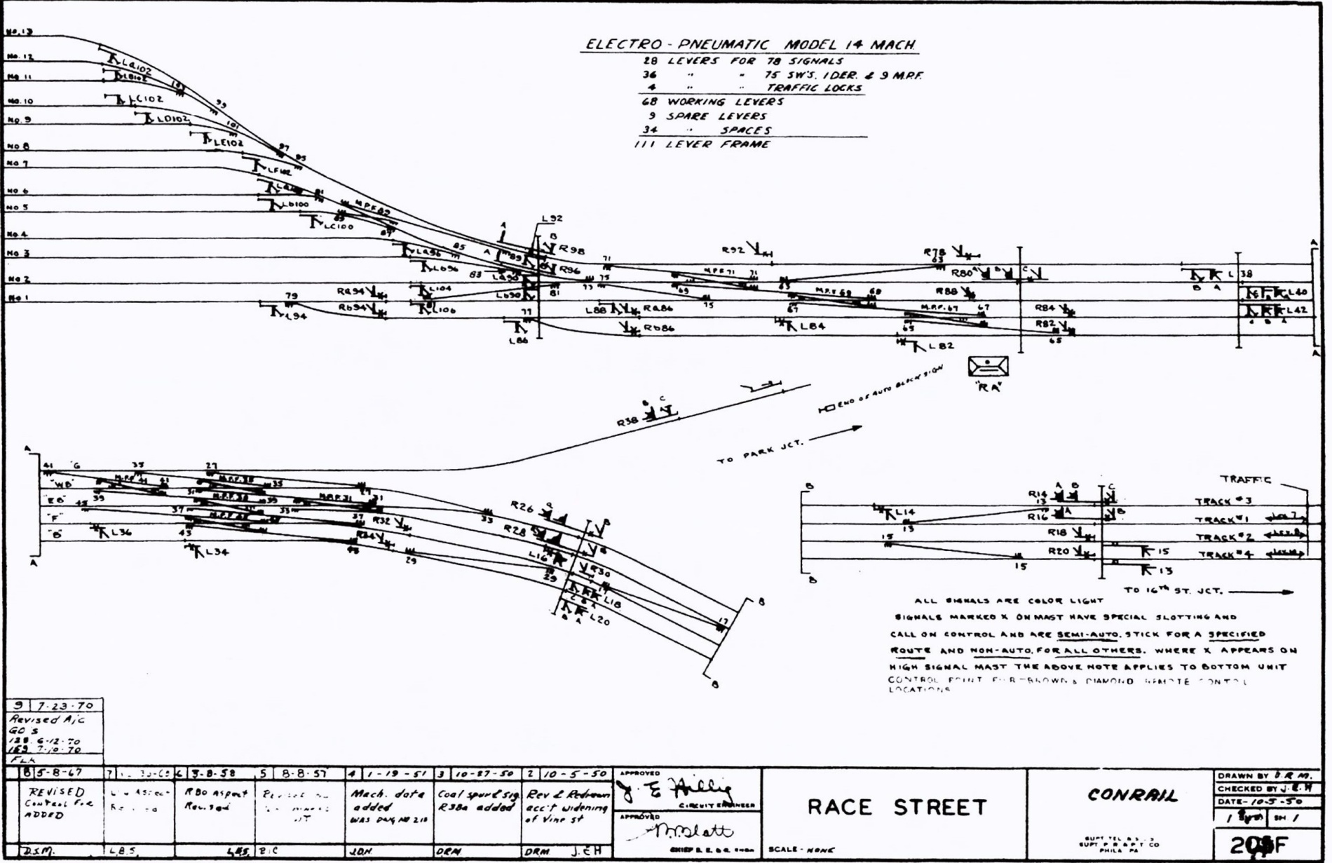
Looping through Center City, the next tower encountered on the SEPTA trunk was MARK. Part of the Market East station complex, I believe it was located somewhere around the ticket counter / station master's office on the east end. MARK arguably replaced the 111 lever Model 14 RACE ST interlocking plant that controlled the Reading Terminal complex. The Center City Commuter Tunnel shows the gross inefficiency of stub terminals as a the 13 track Reading Terminal complex was able to be replaced by 4 through tracks. MARK "tower" consisted of a US&S unit lever panel in an office controlling VINE, a 4-track full crossover hear the north end of the tunnel, and MARK, an interlocking without any appliances (aka switches, derails, etc) that spanned the length of the Market East station platforms. It did not control the adjacent JUNIPER interlocking located between Market East and Suburban station on tracks 2 and 3. MARK opened in 1984 with the closure of Reading Terminal.

BROAD tower center panel with 20TH ST and SCHUYLKILL interlockings.