Search This Blog

Showing posts with label lever frame. Show all posts

Saturday, September 24, 2022

The Evolution of the Improved Saxby and Farmer Interlocking

In the realm of railroad interlocking machines, what does this...

Have in common with this...

Well they are kind of the same thing, the latter just being an improved version of the former that does away with most of the sweat and tears. Just like dinosaurs evolving into birds, 19th century mechanical interlocking systems evolved into smaller and lighter form factors with more and more automation until the technology reached its ultimate dead end. It might seem that a Union Switch and Signal electro-pneumatic power frame is a completely different piece of kit than the "armstrong" monsters that came before, but if we lift the hood we can see how the past influenced the future.

Setting aside who invented what and when, by the end of the 19th century there were two common mechanical interlocking styles coming out of the UK. The Style "A" Machine used a vertically oriented interlocking grid where lever bars on the Y-axis would interact with locking bars on the X-axis via a system of tappets. This style is what tends up show up in books and diagrams as it is the easiest to visually digest. The other system was the Improved Saxby and Farmer Interlocking, this used a horizontally oriented locking grid with lever bars moving in the x-axis interacting with locking bars in the z-axis via dogs. Regardless of the terminology, the key takeaway here is that there were two primary interlocking systems and Union Switch and Signal wound up with the US license for the Improved Saxby and Farmer variety.


Above is an IS&F implementation at the abandoned Buffalo, Rochester and Pittsburgh Railway tower at C&M Jct near Du Bois, PA. We can see how the lever bars are engaged by rotating shafts. The shafts were in turn attached to cranks that were in turn engaged by rockers that changed the back and forth motion of the large interlocking lever into an up and down motion that then rotated the shaft, ultimately sliding the interlocking bar back and forth in the x-axis (if the interlocking conditions allowed). In the photo below we can see how the rockers engage with the cranks behind the row of levers on an more complete lever frame.

So what does this have to do with a Model 14 machine? Well if we literally lift the hood we immediately find the exact same style of longitudinal lever bars, just slightly smaller and more compact.


Because on "power" interlocking machines tower operators no longer needed large physical levers to throw the switch points via a long length of pipe, all the complex mechanisms needed to convert the back and forth lever motion into longitudinal motion can be replaced by a miniature rotating crank. 


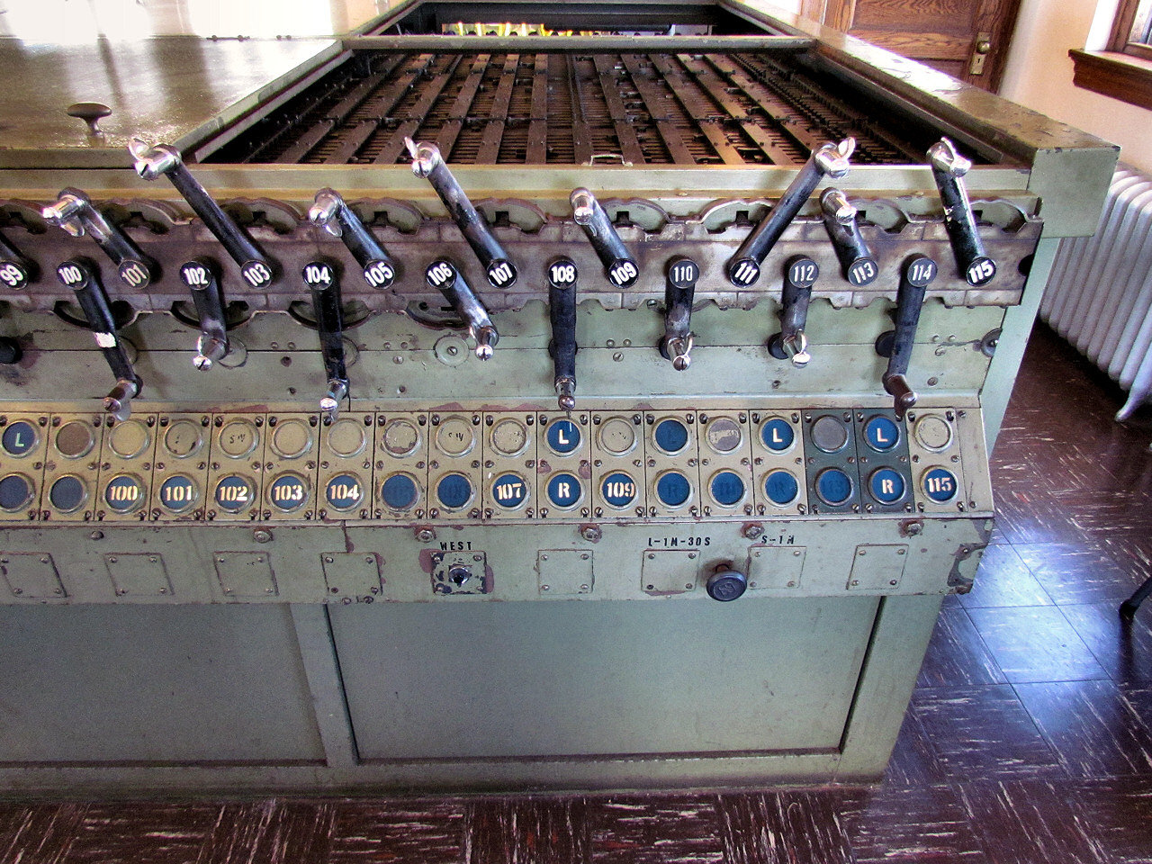
In case you were not yet convinced, the shafts that used to move the lever bars in the x-axis are still around to engage with the locking magnets controlled by the relay logic elsewhere in the tower.


In contrast, the other major type of North American pattern power interlocking machine, the GRS/Taylor "Pistol Grip" type, used the vertically oriented type of locking grid.


This horizontal vs vertical orientation explains why the largest Style "A" type frames were often in tall/narrow buildings, like STATELINE while the largest IS&F frames were in squat buildings such as DOLTON JCT.

STATELINE Tower Outside

STATELINE Tower Inside

DOLTON JCT Tower Outsde

DOLTON JCT Tower Inside

The US&S "Model 14" type interlocking machine was not even the final iteration of the Improved Saxby and Farmer type interlocking! That distinction belongs to the Westinghouse Brake and Saxby Signals Style V machine developed for the London Underground in the 1950's and used as late as 1967 for the all new London Victoria Line. The Style V was a Model 14 style locking bed turned on a vertical orientation with the levers being remotely actuated, typically using compressed air, allowing the interlocking to be remote controlled. I will probably give Style V's their own post at some point, but I wanted to give them a little shout-out in this context. Here we can see a Style V in action a bit after 1:31:25 in a 1960's Victoria Line construction public information film.


In its time railroad signaling was at the vanguard of high tech right along with the telephone system. With the pace of technology today, it is hard to believe that the concept of IS&F mechanical interlocking would be in use from before electric traction was invented up through the ATO equipped Victoria line. I guess it will sort of be how flavors of Z80 microprocessor will be in mainstream use, decades into the future.

Wednesday, August 7, 2013

PHOTOS: SS44 BERK (and the SoNoToMo)

The South Norwalk Tower Museum comprises the old New Haven Railroad's SS44 (aka BERK) tower in South Norwalk (SoNo) , CT (map) preserved the way it was when it was closed around 1986.

The former New Haven RR main line is operated by Metro North Commuter Railroad, which, unlike is sister Long Island Railroad (this is also operated under the umbrella Metropolitan Transportation Authority), chose to ruin two of the most interesting stretches of classic signaling in the country by replacing forests of searchlights on overhead gantries with a waysideless CSS with 3-aspect dwarf signals at interlockings.

Ironically Metro North did a fairly good job of preserving all of the closed interlocking towers. One of these, SS44 in South Norwalk, was of the brick walled mechanical variety and after being boarded up was eventually sold to a preservation group in the mid-90's who painstakingly restored the tower as a museum. It is probably the only preserved tower with a substantial mechanical lever frame in North America, and a must visit for signal enthusiast visiting the New York City area. Here is a front view of SS44 taken from a passing train.


The museum makes most of its money be selling a truly excellent book about itself, so if you want any further information put and order in and help support the museum.

Signaling Station #44 was built around in 1896 before the "classic style" New Haven tower design came into effect with the pioneering overhead AC electrification project of 1906 and second phase of 1918. These later towers are square, cast concrete with or without brick and a hipped tile roof. Here are some examples.

SS22 SHELL

SS26 PIKE

SS28 GREEN
In 1919 the decision was made to upgrade the original interlocking plant at SS44 to support modern interlocking technologies such as electrically operated signals, track circuits, etc instead of attempting to build a new tower.  Despite the attrition of the early 20th century upgrade program  SS44 does still have a surviving sister by ways of SS214 HART in Hartford, CT.  Unfortunately HART was not as well preserved having suffered a fire and is now threatened by demolition.


While the square footprint NH "standard" towers were designed to take all power frames or electro-mechanical frames with lever operated points and miniature lever operated signals, the narrow rectangular SS44 had a 68 lever all mechanical frame made by the Johnson signal corporation. A more accurate term for this frame might be electro-enhanced mechanical as like later E-M frames, like the US&S style S, all the signals are power operated and governed by both track relay logic and mechanical interlocking logic. The frame was well organized with the red signal levers placed at either end sandwiching the blue and black point and FPL levers. All signal for eastward moves were on the west side of the frame and westward moves were on the east side of the frame.


The lever frame has been fully restored and disconnected from the electric-locking so that one can fully exercise the mechanical locking setting up routes and displaying signals. Unlike British practice all of the points are equipped with facing point locks because trains could operate against the current of traffic under train orders on a fairly regular basis. There almost seem to be more locks than point levers!


Saturday, March 16, 2013

CALUMET Tower Closes and Other News

Well this one certainly came in under my radar, but CALUMET tower located on the Indiana Harbour Belt where it crosses the CSX (BO&CT) main line in East Calumet City, IN just closed in early March 2013.  CALUMET was a very old mechanical tower with all the looks and structural integrity of METRA's 16th St crossing only containing a 96-lever National Switch and Signal (later bought by US&S) mechanical lever frame which would help to hold the tower up better.  Calumet Jct consists of the triple crossing between the IHB, B&OCT and EJE lines with the IHB and EJE each crossing the B&OCT on a set of 6 diamonds and then the EJE crossing the IHB via shallow angle movable point diamonds.


 Like all other surviving interlocking towers CALUMET lost a lot of complexity over the years and like DOLTON junction it had its mechanical points swapped for the power operated variety and most of its classic signals swapped for Darth Vader masts, but its ease of access and location at the crossing of two major main lines made it a very popular railfan hotspot, although only for those willing to brave the bad neighborhood it was in.  While no scheduled passenger service passed by CALUMET I personally had the honor of getting a rare mileage trip past during an Amtrak detour over the Porter Branch after a large freight train derailment on the Chicago Line and I am glad I was able to get my own photos of the old girl while where was still someone up top bending the iron.


CALUMET, which one source lists as being built between 1895 and 1897, clearly saw a long and full life and now will probably face the fate that befalls most wooden towers of that type of either being torn down or being burnt down.  There is a slim bit of hope in that the near by GRASSELI tower, which closed in 2007 as the third to last tower with mechanically worked points in North America, was actually preserved and moved to a nearby railroad museum so who knows, perhaps the same motivated individuals are still around to get the IHB to hold back the backhoes and give this tower a new lease on life.  One thing is for sure that is CALUMET is preserved its lever frame will be vastly more interesting to play around with. Unfortunately the once tower rich IHB is down to only about two active plants on its serpentine main line after HICK closed a year or two ago up where it joined the Chicago Line.  The EJE isn't far behind although it two movable bridges with local control towers are unlikely to be put under CTC.


There is of course a Has-Been post on the closing of CALUMET, although that site doesn't seem to like direct inbound links so you might have to re-load the page or cut and paste the link and of course John Roma has been inside to take pictures.

Saturday, February 23, 2013

PHOTOS: A Brief Ride Through DOLTON JUNCTION

For those of you who don't know, Dolton Junction is North America's largest operating mechanical lever frame interlocking tower located about 15 miles south of downtown Chicago. Over a couple of years while traveling on Amtrak Train 50, "The Cardinal" I have had opportunity to photograph the tower and parts of the interlocking and I seeing the ongoing series on Chicago area towers I feel its a good idea to share them here.

The massive complex that is Dolton Junction was created by the intersection of 4 railroad main lines. The Chicago and Western Indiana railroad ran north to Dearborn St Station as a terminal line that concentrated traffic from a number of other railroads, most notably the Chicago and Eastern Illinois, which eventually wound up owned by Union Pacific. Splitting the C&WI were the parallel east-west main lines of the Indiana Harbor Belt and the Baltimore and Ohio, Chicago Terminal railroads. Finally, playing the spoiler and crossing all the of the other main lines at an angle was the Pennsylvania Railroad's "Panhandle Route" main line from Columbus Ohio. Because the PRR was involved you can find an interlocking diagram here.


The tower at Dolton Junction was built in 1897 and contained a 178 lever frame with 100 active levers. As built the interlocking contained a total of 20 diamonds which included an extra 4 from various connection tracks between the main lines. At the time most of the routes through the plant were fitted with split point derails to prevent any catastrophic Stop signal violations.

Today the interlocking plant has seen some expensive reconfigurations carried out on the old mechanical frame. With the removal of the PRR route the number of diamonds has been reduced to 11 and a few new crossovers and connector tracks have been installed. Still the interlocking is operated as an island of manual control with CTC on all sides. Most of my photos were taken from the rear of a south/eastbound train as it passed through the interlocking in 2009.

Entering Dolton Junction from the North we pass the southbound home signal which is back to back with the signals for an independent interlocking that connects the C&WI line with the B&OCT line. The Doton signals stand out as they are older searchlights and not Darth Vaders.


Next we cross the B&OCT diamonds.


Then the IHB diamonds.


And now the tower itself. I believe you can just make out some of the levers inside the open window.


Another angle....


Sunday, April 1, 2012

PHOTOS: Amtrak PAOLI Tower

In today's episode we will take a look inside PAOLI tower via a series of photos that were taken in 2004. As far as I am aware there have been few changes to the tower since then so as of 2010 this information should still be valid. PAOLI Tower was built in 1896 with a mechanical frame and shared design elements with adjacent BRYN MAWR tower and CLY tower a bit further away on the banks of the Susquehanna River. PAOLI was an intermediate design between the generation of all wood towers and the later PRR standard all-brick towers. It literally split the difference with a brick base and a wooden upper story.


PAOLI tower is showing its age with a large brick patch on on its lower level and a large piece of plywood blocking off the location of its bay window that probably succumbed to rot or some such. PAOLI is also suffering from Tower Window Syndrome and as built was fully surrounded by full length double hung windows that have since been boarded over or replaced with modern window types. The tower retained its classic look through the 1960's, but at some point thereafter suffered the blows to its appearance. PAOLI's original PRR style nameplate was later replaced by a more dynamic Penn Central green nameplate and ultimately a plain blue Amtrak nameplate which about 25 years later is heavily faded.


Tuesday, January 3, 2012

PHOTOS: METRA UD Tower

UD Tower in Joliet, Illinois is located at the diamond crossing of the former ATSF (Santa Fe) and the Chicago and Alton main lines and the former Rock Island main line. Of course none of their original railroads exist so today the Rock Island line is owned by the Chicago commuter rail authority METRA to the east and the Iowa Interstate, the line ATSF morphed into BNSF and the Alton was bought by the Gulf Mobile and Ohio, which merged with the Illinois Central which spun off the portion south of Joliet to the Southern Pacific which was then merged into the Union Pacific and with the part north of the city getting folded into Canadian National after the CNIC merger. Finally, both METRA and Amtrak use the former Alton main as guest railroads.

The layout is fairly simple. The ATSF and Alton lines run roughly north-south through the City of Joliet and come together in to an elevated 4-track corridor that then cross the former Rock Island main running east-west at a diamond crossing. This elevated diamond crossing and rail corridor was part of a 1912 project to construct a new Union Station at Joliet serving all three of the major railroads in grade separated splendor. Along with this station came a new interlocking tower to control it which was UD which I assume stands for Union Diamonds or something like that. Like the other Chicago area towers diamonds were the name of the game and in its heyday UD featured a 4x4 grid of diamonds where the 2 main lines met. However today that has been reduced to a 4x1 as the Rock Island really took it on the chin, eventually going bankrupt and nearly being abandoned.

Even tho the 3 main lines were separate UD contained ample crossover facilities between the lines that were used to varying degrees. People might know UD from old pictures usually involving the Southwest Chief and the large signal gantries spanning the parallel main lines covered in semaphore signals. Today the semaphores are long gone, but some of the crossovers do still exist even if they aren't all used much. Today UD sees freight service on all of its lines, but primarily the BNSF route which is a major double stack intermodal route into the BNSF Corwith yard complex. The former Alton line does see some through fright, but it is largely a passenger route with a peak period METRA Heritage service from here to Chicago Union Station , but also Amtrak "Lincoln Service" to St Louis along with the Texas Eagle long distance train. This line is being upgraded to a high speed corridor with 110mph operation. The crossing route sees all day METRA service as part of their Rock Island district so Joliet serves as the terminal of two independent Metra services.

This tower is officially located in the "Western Region" of the United States where I am not properly qualified so I am hazy on various details such as ownership or when parts of the interlocking were modified so I apologize in advance for any missing or inaccurate information about this tower. The following description will contain two primary sources of photos. The first come from an Amtrak trip I took to St Louis in 2005 and cover the Alton alignment in both directions. The second were provided by a railroad affiliate and detail the inside of the tower taken around 2007 or 2008.

I also do not as of yet have a historic interlocking diagram for UD tower, although that might change and I would post it right here in an update.

You can see the entire set of photos here which I have left in their original resolution to help show off the detail contained within. Let me know if you would prefer that I linked to the images directly so that one's browser can scale them properly.

We will begin on the Alton Main running northeast to southwest (railroad east west). Here we are facing UD interlocking (the tower is visible in the distance) on the Alton Main just before it ramps up to the grade seperated alignment at the station. The signals before us are the start of the CN controlled CTC territory. Between here and the limits of UD the line could be considered under ABS rules.


Over on the left we see the rear of UDs home signals and the BNSF ABS entrance signals. At the time the BNSF main was running under single direction ABS rules east of here with a pole line for communications, however overhead photos confirm the both the searchlight and target type color light signals have been replaced by bi-directional traffic lights. Lever numbers are 10 for the reverse direction dwarf, 8 for a straight route on the mast and 6 for a diverging route (which was originally provided by a subsidiary signal).


Moving a bit further and looking back away from the interlocking we see the rear of the westbound home signals on the Alton into UD. The mast signal has been replaced by a modern traffic light type signal which the reverse direction dwarf is an older US&S N-2 unit. Lever number for the dwarf is 11, straight route on the mast is 2 and the diverging route is 3 or 4 depending on an Alton or Santa Fe lineup.


Searchlight automatic signal 72 acts as an exit signal and governs the short distance between UDs limits and the start of CN CTC. We can also see a facing point turnout over on the BNSF main which is worked by levers 14 and 15..


Moving on we find UD's remaining double-slip switch which allows trains on the BNSF route to access the Alton Line. As the tracks curve north of the tower the "diverging" route actually appears to continue on straight. The point of this ladder and a matching one on the opposite side of the interlocking plant was to allow passenger trains on the Alton to platform on the holdout platform at Union Station. For whatever reason this strategy is no longer employed at UD and the matching double slip ladder on the west end of the interlocking was actually removed.

UD is a heavily zoned interlocking with multiple signals along each route. The doubleslip switch and the BNSF facing crossover are in the eastern zone. to the right we can see a rock Island style target color light signal that marks the entrance to the central zone that handles the diamonds. This is a Rock Island style as the US&S supplied triangular target signal has large shade hoods which was a forerunner of today's Darth Vader signal. The doubleslip turnouts are control be levers 40, 41, 43, 47 and 48. The Rock Island style mast is 60 and the dwarf across from it is 59.


>Looking back in the other direction at the doubleslip we can see two floating dwarfs on the reverse direction tracks. These are numbers 36 (Alton) and 31 (Santa Fe). I am sure these used to protect some form of additional turnouts or whatnot.


Here we see UD tower with the east signal gantry. One interesting thing is the presence of subsidiary signals to provide call-on aspects for trains. The BNSF eastbound mast has two heads for the diverging route onto the Alton. This is route signaling territory so that is why the signals here have so much fewer heads than on eastern railroads. From left to right we have the eastbound Alton signal, lever 52 main and 54 subsidiary, then the reverse direction Alton signal (a "high" dwarf) controlled by lever 55, then the westbound Alton "central zone" signal under lever 61 then the eastbound BNSF signal under lever 57 for the main route and levers 56 and 58 for the other two Alton routes.

In this picture we can also see the arrangements for passengers boarding the trains on the Alton tracks. Due to the lack of any under or overpasses trains on the BNSF must be held to allow passengers to board or alight from trains via the duckboards.


Eastbound view of the east gantry showing the front face of the two headed BNSF signal, the eastbound Alton main signal and both subsidiary signals.


The tower is located at the point of the diamond crossings across from the Union Station building which was last renovated around 1990 and apparently is quite nice inside despite the primitive platform conditions. The lever 60 signal on the BNSF is in place to allow trains to be held clear of the passenger platforms so passengers can cross the tracks. There is a closer signal on the edge of the platform, 64, that actually protects the diamond. On the eastbound tracks we see reverse direction dwarf signals 63 (BNSF) and 62 (Alton).


Side view of UD with a Metra MoW truck painted to look like a high visibility vest. The tower is quite long to fit in the lever frame and also tall for all of the relays in the first floor.


Thursday, December 22, 2011

Good News From Down Under

Actually its not Australia I'm talking about today, but New Zealand.  Recently I had heard that a re-signaling scheme had been carried out on the Hutt Valley Line, the old signals of which actually had their own website.  Well today I learned that the project only re-directed CTC control from a local US&S panel to a dispatch office in Wellington.  Even better all the original relay based CTC interlockings were left untouched.

Ok, that's pretty minor, but the news gets better.  While the US&S Model 14 interlocking machines in the US are marching towards extinction with the recent re-signaling projects at ALTO, UNION and WB, US&S parent company Westinghouse did sell power frames based on that same technology overseas to mostly British commonwealth countries as the style L, K, N and B miniature lever frames. They are basically US&S frames just with the levers working back and forth instead of side to side (so the poor signalmen wouldn't get confused ;-) )  Anyway these are about as rare as their breathern here in the United States with only a handful of examples still in main line operation in the UK and South Africa.  Well today I learned that again, despite some minor re-signaling, not only is the large Style L frame controlling the Wellington, NZ terminal still in service, but it was actually upgraded with three flat panel displays replacing its old bulb lit model board.  Talk about a clash of technologies!!


Not only does that frame survive, but so do three others on the North Island Main Trunk at Tawa, Porirua and Plimmerton with Porirua being in use daily and only Tawa being "generally known" about.  Here is a page that has some more up to date information on the Style L machines in New Zealand.


Anyway its nice to know that even if power frames vanish from the United States they can still be found in some nice vacation destinations overseas.  And then if those go you can always check out the pneumatically actuated Style V machines installed on London Transport up through 1999!!  


Thursday, November 17, 2011

PHOTOS: METRA 67TH ST TOWER

Last May Metra closed the last interlocking tower on its Electric Division running south out of Chicago. This was the former Illinois Central suburban routes electrified at 1500 vDC in the 1920's. Like many other high density suburban routes the Metra Electric continued to rely on on manned towers well into the CTC to deal with the traffic volume and complexity of operations. However over the last few years Metra has invested in closing the 3 towers on the line, Randolph Street (terminal office with some sort of relay machine), 67th St and Kensington.

Now I had always assumed that Kensington Tower would be the last to go because it was arguably more complex and also involved a crossing at grade of the CNIC freight main line by the South Shore Line, which diverged from the Metra Electric line there. Because of the three separate entities involved I figured a fight over funding and service quality would keep Kensington open. I was also under the impression that 67th St was some sort of more modern type relay based machine and Kensington was an ancient GRS pistol grip frame as that was how each was listed on the large Jon Roma list of towers. Turns out I had it completely backwards. Kensington had been converted to a relay plant controlled by a GRS TrafficMaster CTC console (and was originally a US&S plant), while 67th St had the GRS machine. Also I thought 67th St was some small office buried somewhere around the junction, while in reality it was a full on tower hiding in plain sight next to the tracks. I just never noticed it.

Anyway, I spotted this Blog piece on the closing of the last of the Metra Electric div towers and along with a good history of the tower (which you should read) there was a very tantalizing interior photo of the GRS Model 5 machine inside. I managed to track down the man who took the photos who was nice enough to send me his whole set on CD with permission to post them online and use them in my photo essays. The photos have been unmodified (apart from renaming) and left at their original resolutions to preserve the details inside the tower so you might want to click "View Image" to get the full amount of detail. The entire set may be viewed here.

Jumping right in, here is the best photo of 67th St that was provided showing a Metra Highliner EMU making a station stop in fairly typical Chicago weather. The tower is a large rectangular monolith with no typical "tower" accouterments, which is why I probably mistook it for a substation. What gives it away however is the massive arm bundles of signaling wires running out from the tower onto a local concrete pole line.  67th Street is located at the junction of the IC Main Line and the electrified South Chicago Branch which runs to a station only a short distance from the Quad Draws at CP-509.


 I should probably provide a little reference at this point. Here is a line guide to the Metra Electric division. There is an updated track chart at the bottom showing current CTC (red) and ABS (green) territories. both 67th St (MP 14) and Kensington (MP 19) interlockings used to be blue, indicating tower control. Express tracks are on the outside, local tracks on the inside serving island platforms. The tracks between 67th St and Kensington was upgraded to bi-directional operation some time ago, but between 67th St and Chicago it remains ABS. Moreover, between Roosevelt Rd and the Randolph St terminal, trains work on sight within unsignaled yard limits with hand operated points.

https://www.chicagorailfan.com/mmelec.html

Back to the tower we head to the top floor where we find a surprisingly large 176-lever GRA Model 5 pistol grip style interlocking machine. While only a small fraction of the levers were in use at the time of its closure, back in the day the tower would have also had control of the 4 parallel freight tracks. Here we have the left side of the machine starting at lever 1.


And continuing to lever 176 on the right. 


As per standard practice red levers are signals, black the switches. Here is some detail of the 8x levers. Pulled out from the machine displays a signal or reverses a switch. The small button on the pistol grip is not interlocked, but instead is covered by any blocking device. The red buttons are for displaying a call-on signal.


View along the levers showing the glass top of the machine and a scented candle. One wonders how often that glass top needed to be repaired in the 80 years the tower operated. 


Here is a view of the machine straight on. From top to bottom we have the illuminated track diagram, then the row of signal rundown timers (supplied by US&S) with an emergency switch release box. then a glass fronted case switch and signal fuses and finally the levers. Is it just me or are the stickers on the fuse case sending some mixed messages? 


Here is the right side of the track diagram showing off the north end of the interlocking. This consisted of a 4-track double slip scissors crossover employing levers 132 to 176. As the route north of here is ABS the tower only has full occupancy lights on the southbound tracks. Below the diagram is a display showing which levers are currently locked out, next to some truly ancient portable radios.


The left side of the track diagram shows off the south end of the interlocking which consists of a duckunder junction for trains proceeding down the South Chicago branch. Main line local train must make a diverging movement at the split. Past the South Chicago split we see a double slip trailing ladder allowing express to local crossover. Also note the traffic flow indications for the bi-directional territory south of 67th St.