Search This Blog

Showing posts with label Caught on Camera. Show all posts

Tuesday, July 7, 2026

Caught on Camera: Clear to Next Interlocking for UP #4014

For much of the Union Pacific Big Boy 2026 Coast to Coast excursion tour, #4014 was able to operate like any other Class 1 main line locomotive with an ETMS PTC box in the cab allowing the engine to operate in the leading position. However the former Pennsylvania Railroad Main Line between Harrisburg and Rochester, Pennsylvania not only remains cab signal equipped, but was converted to operation without wayside intermediate signals in 2018. Until recently Union Pacific was also a major user of continuous cab signals, however in 2022 they chose to scrap their system due to legacy design considerations that created a lack of synergy with ETMS. While it would have certainly been possible to reactivate the cab signals on #4014 and integrate them with ETMS, the increasingly popular solution to run the movement under Rule 280a, Clear to Next Interlocking, was chosen. I was able to catch this procedure at CP-ROCKVILLE on July 7th, 2026.

Here we can see the westbound track 2 signal at CP-ROCKVILLE displaying Slow Approach, R/R/*Y*, with the "C" lamp illuminated for a stop signal at CP-MARY about 5000 feet to the west on track #1. When the dispatcher lines a route between CP-MARY and CP-BANKS, the signal at CP-ROCKVILLE upgrades to R/Y/R Medium Approach with the "C" lamp lit. The plan for #4014 was to proceed past the far end of CP-MARY and then reverse into Enola Yard to spend the night. Note that the Slow Approach and "C" lamps are flashing with the  same cadence. This indicates that the interlocking has a single source for pulsed lamp current that is then directed to the lamps that require it.

Sunday, May 31, 2026

Caught on Camera: Track Circuits and Electrification Current

In a previous post covering the phenomena of a "bobbing" track signal that cycles intermittently between one or more states. I mostly covered the spectacle of a particularly egregious example on SEPTA's former Reading Main Line. Here I will cover two additional examples that are a bit more tame, but sheds some light into some operational side effects that come with railroad electrification. 

PATCO FERRY interlocking with an eastbound train on the troublesone WF2 track circuit.

The first example was caught on the PATCO Speedline and involves the cab signal bobbing between 30mph (Approach) to 65 mph (Clear) immediately after a westbound train crossed over to the eastbound track just past the Ferry Avenue interlocking. Was this cased by standing water or a lose wire? Apparently this bobbing signal is a known issue that occurs when the operator or ATO system selects the P4 power setting after exiting the turnout.  The current draw causes the WF2 track circuit relay at West Ferry interlocking to drop.  With the WF2 and NJ67 track circuits both occupied, the signaling system thinks that the train is still on the 30mph switch at West Ferry and drops the cab signal from Clear to Approach.  The train cuts power, the WF2 relay picks up, the signaling system "sees" the train off the 30mph switch and upgrades the cab signal to Clear again.  The process continues until the train passes the next code change point.

As I explained in my post regarding impedance bonds, the rails serve double duty as both a path for traction return current and the track circuit. Because of this a mis-calibrated signaling component can be affected by the acceleration state of nearby trains.    A "safe" failure of this type is less likely to be tested for upon installation or fixed quickly once identifies.  A good example of this is the southern segment of Amtrak's Northeast Corridor that still utilizes relay--based signaling hardware from the early 1980's.

Like with the PATCO example I have been told that the interaction between the signaling system and electrification can be to blame, especially from trains traveling on adjacent tracks. The first example was located at the northbound Milepost 69 intermediate signal near Aberdeen on the less frequently utilized center track #2. The signal can be seen slowly cycling between Clear and Approach, potentially due to an electric train movement on one of the outer "through "tracks". 

Here we see a slightly more extreme example as the southbound Milepost 103 intermediate signal on track #2 at Halethorpe rapidly flickers between Approach and Clear. It might look like Advance Approach is trying to display, but the signal blocks ahead are of usual length and the flicker interval is not uniform. This was noticed after the passage of a southbound Amtrak electric train on track #1. This instance of signal bobbing would also be likely to avoid rapid resolution as track #2 is less frequently used than tracks 1 and 3 and for at least half the day traffic is set in the opposite direction. 

Milepost 103 signal location with track #2 set northbound

Years ago when I had access to Amtrak NEC reports, there would be bobbing signal issues that would persist indefinitely. When the cause is an intermediate side effect of the electric traction system, these problems can become very difficult to troubleshoot as they might require a train running at some specific power load/speed to trigger the problem. A big reason central European countries are so enamoured with axle counters is that many electrified before installing automatic signaling. Counters solve both the problems associated with impedance bonds, but also problems like bobbing signals. 

Wednesday, April 29, 2026

Caught on Camera: New CSX Signal Rules in Action

A few months ago I posted about CSX's two new "Canadian" style signal rules, 281E Limited Approach Medium and 281F Limited Approach Limited, to augment its existing Rule 283A Medium Approach Medium and 283B Medium Approach Slow. Although established in 2024, I had not been expecting to catch one in the wild for some time as railroads tend to bend over backwards to avoid signal modifications if they can be avoided. Sightings of the new signal indications had mostly been in former Seaboard System territory in Georgia and Florida. Therefore you can imagine my surprise when, after stepping off Amtrak Empire Service Train 281, I saw a Rule 281D Limited Approach upgrade to Rule 281F, Limited Approach Limited at Chicago Line interlocking CP-292.

Now Rule 281D Limited Approach has been present on the Seaboard main lines for several decades, and although it is an odd duck, by seeming to authorize Limited speed up to a stop signal instead of Medium, this could have been present as part of the general Chicago Line re-signaling of the 2010's. The Rule 281F indication has to have been added since September 2024  so that is evidence of more system-wide changes on the part of CSX. 

As to why CSX is retrofitting existing interlockings as opposed to using 281E/F only in new projects my guess would be this is a downstream cost of PTC speed enforcement. Not so much in the sense that crews would "cheat" when 283A Medium Approach Medium was displayed for Limited Speed turnouts (although they probably did), but PTC's conservative braking curves could be raising the cost of signal indications that leave speed on the table. 


Friday, February 20, 2026

Caught on Camera: PORTAL's new "Gantrylever" Under Test

Following up on the previous post regarding the new PORTAL bridge cutover, Amtrak I happened to catch a cab speed indication on the (New) PORTAL interlocking's westbound cantilever mast's 3W signal. With the new track #3 still very much under construction, crews were getting a jump on commissioning* the new interlockings associated with the project. Although this is a static image, the 3W was displaying a flashing green cab speed indication, which would be in line with the high density cab signaling in place between HUDSON and A interlocking at Penn Station. 

That alone is interesting, but if you review the track and signal diagram from Bulletin Order establishing OLD PORTAL and OLD SWIFT interlockings you might notice that future PORTAL is intended to be laid out similarly to OLD PORTAL with center Track A merging into tracks 2 and 3. Instead in the photo we see a two track cantilever mast, or do we?


Amtrak is splitting the commissioning of the new Portal fixed bridge into two month-long work sessions spaced 6 months apart. The primary reason for this is that activating the new eastbound track #2 will require the prior removal of overhead catenary supports required for both existing tracks. A secondary reason is that the new track 2 will require partly burying the old track 3 and removing the westbound cantilever as you can see below. 


If you look closely the end of the cantilever arm has some extra bits and the diagonal supports at the corner seem a bit flimsy. This is because that new signal structure is not a cantilever, but half of a three track signal gantry that will be completed once its southern foundation has something to sit on. I'd call this a "gantrylever", but that term is somewhat taken by gantry+cantilever combinations as seen at UNION and DUNTON. 


 In other news related to PORTAL's signaling  the lower heads on the westbound signals are conforming to the new pattern established at LEGGETT interlocking on the Hellgate Line, replacing the central lunar white Stop and Proceed dot with a a lunar white Restricting \. However the eastbound signal masts retain the Stop and Proceed dot. This might be a quirk needing the shorter signal blocks around Secaucas transfer than the SWIFT connection. 

Anyway. just though it was cool to catch the new temporary cantilever signal 3E under test, several weeks before the first revenue train would actually use the new bridge.

*Note: Amtrak would ultimately open track 3 for service two days ahead of schedule due to a problem that fouled track #2 during the morning rush. 


Sunday, December 14, 2025

Caught on Camera - NORAC's Missing Signal Aspect

If you are looking at older versions of the NORAC signal aspect chart you might notice something a bit odd. Most of the common signals indication have a dwarf option for situations with restricted clearance like tunnels or terminal areas. Because of the understandable choice to limit dwarf signals to 1 or 2 elements, some uncommon aspects like R/Y/G Medium Approach Medium are omitted, however until 2018 NORAC also omitted a far more popular signal, Rule 285 "Approach". For those of you who have been living in a cave, Approach, also known as "Caution" in the UK, is "the yellow light" in railroad signaling. A signal so basic that it appears in elementary school books on how trains work. How Rule 285 was neglected in dwarf form is an interesting story of path dependence. 

The story begins with the lamp color yellow performing double duty as for the Restricting indication. When shown alone on a dwarf signal, yellow Restricting, not Approach, so Approach has to be something else. Well, we have two lamps so why not make Approach Y/R? Well dwarf signals are most often used in terminals, terminals are slow so dwarfs really need a Slow Approach indication.  Single lamp *Y* flashing yellow exists and is the preferred option, but back in the day flashing relays were expensive and unreliable so we should probably have a fixed version of Slow Approach. This is where the fateful choice was made. R/Y Slow Approach could have worked. If the Red lamps burns out the signal becomes a Restricting, but the rules boffins likely didn't want R/Y Restricting on a high signal to be confused with R/Y Slow Approach on a dwarf signal because that mistake would likely result in an accident. Therefore dwarf R/Y was given to Restricting, Y/R was given to Slow Approach and Rule 285 Approach was out of luck.

Slow Approach on Track 1 east at CP-97 instead of Approach.

For the sake of correctness NORAC did offer Rule 285 Approach in the form of a PRR pedestal or a B&O dwarf CPL, but these were never options in color light territory or after position light signals began to be phased out. So what was a railroad to do when it needed Rule 285 in a restricted clearance situation? First option was to use Slow Approach, one loses 15mph within interlocking limits, but outside of interlocking limits the rule becomes "regular" approach with a Medium speed limit. The second option was to use Y/*R* Medium Approach, this bumps the speed passing the signal up from Slow to Medium, but ultimately suffers from the same drawback as Slow Approach in that trains can't come at either of these substitutes on a Clear, trains have to hit an Approach Medium or an Approach Slow first. From my field observations Medium Approach was the preferred alternative and could be displayed on either a 2 or 3 lamp modular stack by lighting the yellow lamp and flashing the red below it.


To be fair, the Seaboard system used by CSX also exhibits this problem despite using only using lunar for Restricting with dwarf Y/R for Slow Approach and R/Y for Medium Approach. By forgoing a flashing medium approach CSX lost its latitude for an "easy" dwarf approach aspect. However it was ultimately NORAC that cracked first and in 2018 they adopted *Y*/R as the dwarf option for "straight" Rule 285 Approach. While this now leaves Rule 282a Advance Approach out in the cold, Approach Medium is pretty much a lossless substitute. Of course these sorts of changes can take some time to filter down and it was only recently where I managed to catch one in the wild at SEPTA's WAYNE JCT where a dwarf has replaced a high signal at the end of a platform.


With this change the ball lands back in CSX's court. Will they make some basic changes to its system like adopting *Y* Advance Approach in addition to *Y*/R dwarf Approach?  Or will they keep looking for more "Canadian Combinations".


Sunday, October 5, 2025

Dispatcher Signal Stacking

The story of railway signaling, like many others, has been one of technology increasing human productivity. Power operation allowed "levers" to be thrown faster, N-X machines allowed routes to be set with fewer button presses and remote operation combined with CTC allowed one person to control many miles of track. However remote control and ease of operation were not the only types of automation added to towers and dispatch offices. Fleeting allowed infrequently manipulated interlockings to do the same thing over and over and in cases where routing decisions needed to be made, automatic route setting combined with train labeling could keep track of train movements and automatically request routes as they approached junction points.

Recently another method of automation has crept into dispatch software, route stacking. While similar to automatic route setting, it is different in a significant way. Consider the following pair of photos showing an Amtrak Springfield shuttle train departing SPRING interlocking at Springfield Union Station.  


Within seconds of clearing the interlocking the 2N dwarf signal (upper right of the photo) changes from Stop to Restricting for an opposing movement. In the past this would signify a very attentive dispatcher, hovering over their CTC panel or video display, ready to line the new route as soon as possible. If this was an auto-routing system we would have had to wait for the opposing movement  to enter the track segment to trigger the route request.  With stacking the dispatcher simply uses their computerized dispatching interface to queue up a sequence of routes which will be executed as soon as the last established route is taken. Then they can do and pay attention to something else.  


This works well at places like Springfield where reverse movements are common. For a northbound train the dispatcher could set up a route from the 2S at SWEENEY, 12 switch reverse. Then immediately have a second route set for the 1N 13 switch reverse to the CT River Main Line.  It's not super complicated, but it is something that, due to the time penalties associated with bad routes, took a little while to catch on.

Tuesday, September 30, 2025

Amtrak's Secaucus High Density Cab Signaling in Action

When the Secaucus transfer was being designed and built around the year 2000, Amtrak implemented a new "High Density Cab Signaling" concept with shorter blocks and additional cab signal codes in order to increase the capacity of the approach into Penn Station especially with all the NJT Corridor and Midtown Direct trains stopping at Secaucus. This would replace the PRR era Rule 261 signaling with mile long blocks. Below we see the 2E signal at ERIE interlocking cycle through its indications after an eastbound NJT push-pull takes a Clear signal upon departing the track 2 station platform. 2E was fleeted for a normal route and immediately went to Stop and Proceed, then Slow Approach, Approach, Approach Limited and  finally Cab Speed (which could represent both 60 and 80mph speed codes). The horn at the end was an approaching Amtrak Regional which ultimately took 2E at Clear (not captured on video).

Unfortunately this was just in time for NJT to lean into Push-Pull service which lacked the acceleration to and braking systems to take advantage of the rapidly changing speed codes. On push-pull sets with traditional air brakes, crews would often target one speed below the one being displayed to avoid jerky train handling and the risk of penalty brake applications in the face of frequent cab signal drops.This negated much of the intended speed benefits from the high density cab signals. For whatever reason, similar High Density Cab Signals could be found on the 2005 era western Harrisburg Line re-signaling, however due to the low traffic density, Amtrak has taken to disabling some of these extra code change points.

Friday, February 28, 2025

Caught on Camera: Double Green Clear

 With the CSX takeover of the former Guilford Rail System empire, there's a real risk that we might see the end of double green clear signal indications in the wild. Most commonly associated with the New York Central, double green clear is an artifact of two position ABS semaphore signals with an upper head of R+G and a lower head of Y+G resulting in the combination of R/Y for Stop and Proceed, G/Y for Approach and G/G for clear. A part of the NORAC set of signal indications, its last common use was in New Englande on the former Boston and Main territory operated by the Guilford Rail System and the MBTA.

As previously covered, while Guilford wasn't perfect it did maintain a bunch of legacy signaling practices, like bracket masts, up into the 21st century. Even in places where new signals were being installed, two head "distant" signals to interlockings would still display G/G as opposed to G/R. In fact you can see it for yourself on Google Street view on the milepost 2xx intermediate signal adjacent to the Main St grade crossing in downtown Saco, Maine

Lit for an approaching train we see double green clear displayed on a thoroughly modern target type LED mast signal. In fact I saw this street view while scouting Guilford automatic signal locations on Google Maps and was not only able to locate the normally dark (approach lit) signal, but catch it displaying the coveted indication for a northbound Downeaster train. 

Unfortunately it appears that this location will be replaced by CSX within the year with no chance of it retaining the double green clear. However with 5 round trips a day, its pretty easy for anyone in the area to  catch it for themselves. 

Saturday, December 2, 2023

Caught on Camera: CSX's Gonzo Distant Signals

Distant signals, as defined as those that appear in otherwise unsignaled territory to warn train movements of an upcoming absolute signal (ie an interlocking), are seen in two flavors in the North American scene, fixed and dynamic. Many year's ago I discussed the use of dynamic distant signals on some Conrail Shared Assets lines in Southern New Jersey and although fixed distant signals are far more common, dynamic distants aren't remarkably rare. Today, most signaling systems make use of two possible distant signal rules. Approach the next signal prepared to stop and approach the next signal expecting a proceed indication of a type defined by route knowledge. As these appear in unsignaled territory neither of these conveys track occupancy information between itself and the absolute signal. CSX on the other hand defined its distant signals by a marker plate that, like the vomiting emoji, can be applied to any signal.

In practice the CSX App Marker would only be applied to Clear, Approach, Approach Limited, Approach Medium, Approach Slow and Restricted Proceed/Restricting. Basically anything that would normally appear on an automatic signal before an interlocking. Now of course this wouldn't be a "Caught on Camera" post if I didn't find an exceptional example of this system. In Cartersville, GA the unsignaled Cartersville Sub approaches the W&A sub at a wye interlocking designed BOWEN. At some point after 2012 CSX re-signaled the W&A sub and installed a new App marked distant signal right off Sugar Valley Road, seen below.


Unlike the typical dynamic distant with two lamps, yellow and green, this example has 5 lamps including a fixed yellow in the uppermost head. This was because the west apex of the wye was interlocked and could give a slow speed route and a medium speed route. Therefore the Sugar Valley Road distant can display Y/R/R Approach for a stop or restricting, Y/G/R Approach Medium for the medium speed route and Y/R/G Approach Slow for the slow speed route. Of course because it doesn't reflect track occupancy the most restrictive indication is Y/R/R Approach as seen here next to an approaching train movement. Ironically, the approach lit distant signal is indirectly reflecting the occupied nature of the block by being lit so at some level, the App Marker lies 😅.

Saturday, November 11, 2023

The Ultimate Cutover - SEPTA 90TH ST JCT SOUTH

Typically when one discusses a signal cutover one is cutting new signal logic over to control new or existing signals or interlocking appliances. Sometimes one will cut new signals or interlocking appliances into existing signal logic. However in 2014 when SEPTA wanted to relocate 90TH ST JCT SOUTH interlocking 2000 feet to the north to expand a Conrail SAO industrial siding they took things a step further and relocated the entire signaling bungalow.

Above is a street view of the original location in 2014. Below is the new location in 2015. SEPTA didn't even bother to clean the graffiti off the relay hut.

Part of the penny pinching shown here is due to 90TH ST JCT SOUTH being solely the domain of Conrail freight movements before they hit the SEPTA Airport Line at 90TH ST JCT NORTH. Without a Federal or State grant to pay for the capital improvement, there was no incentive to pad things out and create more jobs and with traffic being pretty minimal there wasn't a cost incentive to minimize down time due to testing. This just goes to show when the costs align, railroads will save money on signaling.

Sunday, June 18, 2023

Caught on Camera: Mendon, MO Level Crossing

 One side effect of taking photos from the back of long distance Amtrak trains is that from time to time you get a good shot of what might end up in a national news story. When the Mendon, Missouri grade crossing accident and derailment first took place in the summer of 2022 my impression was that it was located at a random farm crossing in the middle of nowhere. Since the former ATSF main line lost its searchlight signals over a decade ago there was no real need to check on the status of a notable signal such as this Conrail era signal that almost got wiped out in an Columbus, OH area derailment.  


Anyway, while watching the above Plainly Difficult production on the incident, I spotted what appeared to be a signal location adjacent to the collision site on County Road 113. Checking the archives I discovered a clear photo of the accident site along with the Milepost 363 intermediate signals taken from the rear of the Southwest Chief in 2013.

In addition to the signals and the unprotected grade crossing we can also see the ATS inductors that allowed for 90mph speeds across the state of Missouri. These had been recently removed by the time of the accident due to PTC making the legacy system unnecessary.  Anyway the moral of the story is to take photos of everything because you'll never know what might be historically significant.

Sunday, June 4, 2023

Caught on Camera: Bastard A-5

While getting photos around the JO section of ZOO interlocking I noticed some interesting writing on the A-5 pneumatic point machine attached to the 131 switch.


In stenciling the signaling department appears to have labeled the point machine as a "bastard". Someone else, perhaps another employee, perhaps a local, has expanded upon this with "/whore". Given that the points appear to show evidence of a recent rebuild, it is possible that this A-5 has been assembled from the parts of others or contain a non-standard modification. I believe that A-5's have a notion of handedness that could be at play here. If whatever the modification was not entirely successful that could have resulted in the editorial comment.

Saturday, January 28, 2023

Caught on Camera: The US&S M22

The Union Switch and Signal M3 series of switch machines (including the M3, M23 and A and B models of both) is so ubiquitous and has been around for so long that one might assume the model spring fully formed from the head of George Westinghouse. However it is important to remember that the "M" is the family, not M3 and unlike General Railway Signal, where their switch machines Models 1 through 4 were radically different than the Model 5, the US&S Style M has remained fairly consistent since its introduction in 1918. In fact one of the reasons its easy to assume that the M3 (or M23) has been around far longer than its actual introduction date of 1951, is because the M22 is similar enough that both times I encountered one in the wild, I only noticed the machine was actually an M22 when I was performing unrelated photo research years later. 

To review, above is an US&S M23 switch machine as previously installed on the former C&O Washington Sub near Charlottesville, VA. Below is an M22 switch machine as previously installed about 10 miles to the east in Gordonsville, VA.

I'm not going to go into all the technical details as to how they differ, there's already a page for that, but the big giveaway for an M22 vs an M23 is the non-concentric selector lever that swaps the machine between manual and power operation. The second giveaway is the bolt pattern on the top of the central gearbox with the M23 having 2 large bolts and the M2 4 smaller bolts and a more bulbous cover. Unfortunately I have yet to encounter an M2 in the wild and from the few photos online I cannot determine an easy way to differentiate it from an M3. Anyway, these and any other M22's along the former C&O Cardinal Route (now operated by the Buckingham Branch shortline) were removed in a 2013/2014 re-signaling project.  However there is another M22 I just discovered situated about 5 feet from a busy public right of way.

It's this fellow, the northern end of the #1 crossover at CP-ASH in sunny downtown San Diego. In fact its directly adjacent to the Little Italy light rail station.

Although my photo is from 2015, a quick check of Google Street View shows that it is still in place as of October, 2022.

So if you happen to be in San Diego or out and around some rail line that hasn't seen a switch replacement since 1951, know how to spot an M22 and make sure you take plenty of photos if you come across one.

Saturday, February 5, 2022

Approach, Three Ways

 About a year ago I stopped by a local interlocking in the depths of Camden, NJ with a rich Pennsylvania-Reading Seashore Lines history.  CP-BROWN, formerly BROWN tower, is located at the junction of the former West Jersey and Seashore line to Vineland and other points south and the former Atlantic City Railroad Line to Ocean City and Cape May. In 2002 CP-BROWN and the adjacent CP-MILL were changed from position light to Conrail style color light.  15 years later as rail traffic to various South Jersey port facilities increased, Conrail Shared Assets re-signaled CP-BROWN again, adding a new interlocked switch to the former Bulson St yard, but in the process they also modified the northbound signals to reflect new conditions at CP-MILL, specifically the end of signaled track northbound.  

Under NORAC, the signal before a Restricting indication is an Approach type indication and CP-BROWN just happens to have the complete set of NORAC Approach type indications spread across three masts that can display only that and Restricting.  

Main track northbound signal 2N-1 offers up a straight Approach indication with an upper head yellow lamp and Restricting with a lower head yellow lamp.

Signal 2N-2 off the Beesley's Point secondary offers a single yellow lamp on the lower head that is used for both R/Y Restricting and R/*Y* Medium Approach.

 Finally the signal off the Bulson St track offers a single yellow lamp on the lowest head for R/R/Y Restricting and R/R/*Y* Slow Approach.  Note, aside from red, all the lamps on the upper two heads are blank. For whatever reason each head has the complete package of triangular mounted SafeTrain CL-20s and sun visor. 

So there you go.  Three masts, three Approach-type type indications in each of the three speeds (Full, Medium and Slow) with Restricting the only other option.  Pretty neat!


Tuesday, December 28, 2021

Caught on Camera: Amtrak's Two Indication Block Signals?

 Twice in the last year I have had the fortune to catch and video the strange situation of Amtrak intermediate signals transitioning directly from Stop and Proceed to Clear.  The first was at the 592 automatic on track #1 eastbound at Irishtown Road, part of the ~2006 Rule 562 CTC project, after the passage of the eastbound Train 42 Pennsylvanian.  The second instance was at the 133 automatic on track #4 westbound in Radnor, PA, an origional PRR signal dating from at least 1948, after the passage of a westbound SEPTA local. 


This effect is not universal so I don't think Amtrak has gone around systematically eliminating the Approach indication for "safety" reasons (although I wouldn't put it past them) so my best guess is that the 75ppm code generator at the next signal location down the line has failed resulting in the featured locations seeing a 0 code for an occupied block. Because train traffic hasn't been busy enough for one train to be running behind another, I suspect that in both cases the defects had simply not been noticed/reported.

Tuesday, October 26, 2021

Caught on Camera: Phantom Indication @ DAVIS?

 Was processing photos from a visit to DAVIS interlocking at Newark, Delaware on Amtrak's NEC and I caught what looked like a phantom or improperly displayed signal indication on the 2N position light signal.  The upper head is displaying Clear in the normal manner, but the lower head appears to have the 12 o'clock (green) lamp lit.  Normally this is used as part of the lower | Medium Clear indications, but today is making up half of an NY Central style double green clear. 

I can't tell if this is a trick of the light or indication of stray current in the signaling hardware. 🤔 Argue in the comments ;-)

Saturday, July 31, 2021

Caught on Camera: Modern Signaling Inside Tours

Just discovered this recent video from a Union Pacific signal maintainer giving a tour of a modern interlocking hut and other signal relay cabinets.  While getting the occasional photo inside one of these is not all that uncommon, narrated videos from North America are almost unheard of.  Anyway I'm not going to summarize the whole video, but some important takeaways are as follows. 

  • Compare how little has changed between a 2019 setup and this 1992 setup I profiled from GREENBELT interlocking.  The US&S Microlock II card based, microprocessor controlled vital interlocking hardware especially.

  • Track circuits, switch motor controllers and possibly signal lamps are still still relay controlled and not even the solid state upgrade variety.

  • The local control board has reached peak levels of simplification/cheapness.

  • Make sure you watch the whole video for a tour of a 1980's or 90's Southern Pacific all-relay interlocking hut at the end for comparison.

  • The wiring job is quite professional.  I'm not sure if the installers have put more points into wiring over time or have benefited from computer aided routing.

In this video he discusses power operated point machines (specifically a US&S M23), however also heads into the relay hut to locally throw the unit.  Here we see an example of the protracted throw times that used to be common for low voltage DC operated points.  Due to the gear ratio, the motor takes around 20-30 seconds to throw the switch points as opposed to 1-2 seconds seen on 120v examples.

We also have a complete guide to electric hand throw switch locks and their operation.


In addition he posted a video tour of a grade crossing relay cabin, which, although not my wheelhouse, interacts with the signal system in some interesting ways. The first crossing profiled uses a speed predictor that uses audio frequency overlay circuits to directly measure the speed of the train instead of a fancy wireless negotiation. Others still have quite a few electro-mechanical relays present in various roles.


Monday, June 14, 2021

P&LE Tower Update - CP-3Y Demolished

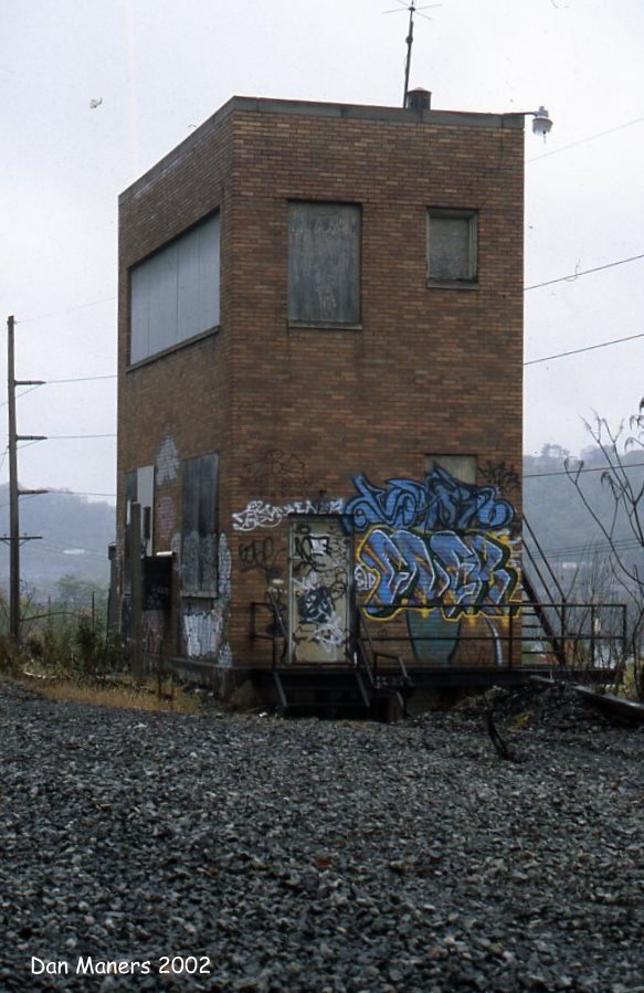
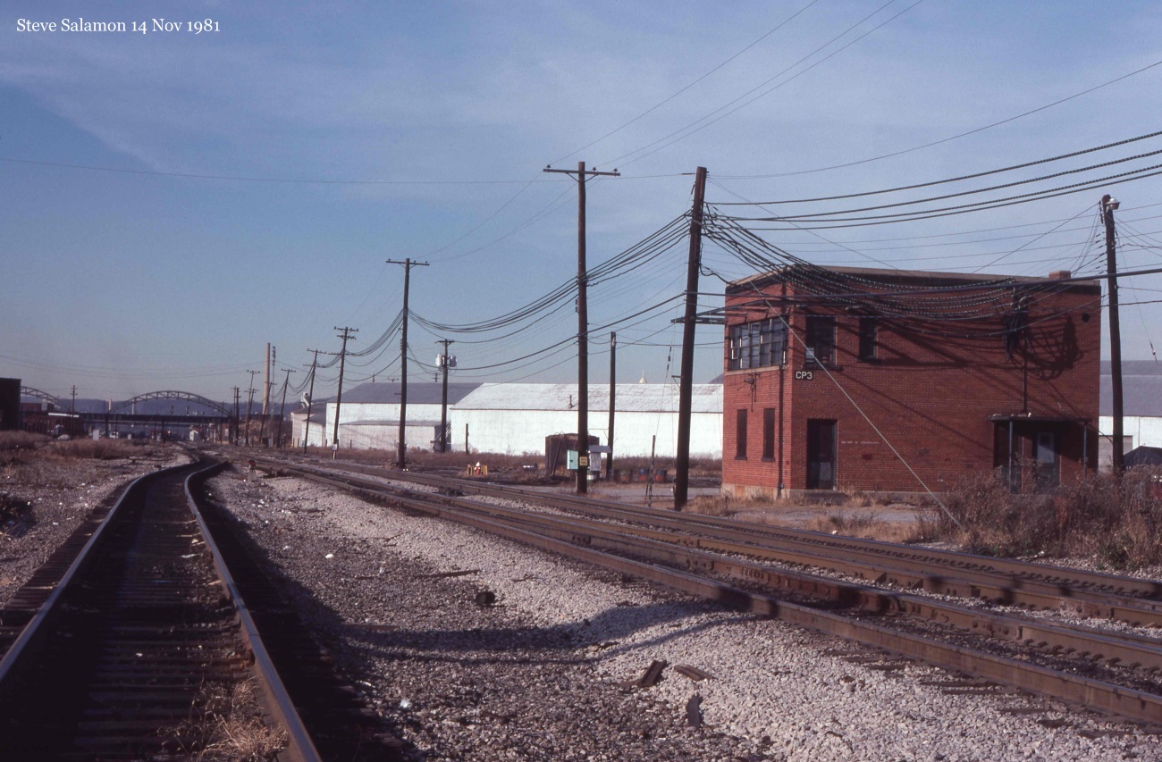
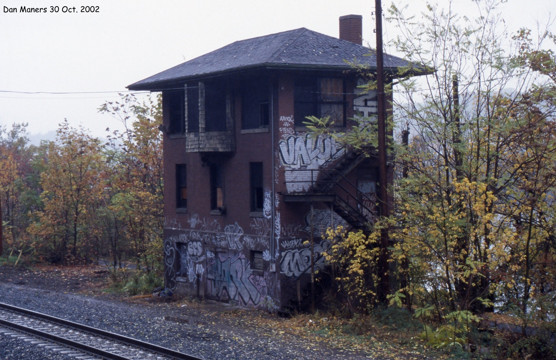
 A couple years ago I posted a piece on how to use Google Street View to check on the status of surviving interlocking towers.  At the time I determined that the former PRR tower BECK and the former P&LE tower CP-3 had both been demolished, while the P&LE tower CP-3Y was still standing. At the time I was using the latest Street View image from July 2016, which showed the existence of CP-3Y.

However what i did not know that was a new set of images from August 2018 were still in the pipeline and would have revealed that CP-3Y had indeed been demolished in the intervening time period. I believe this would eliminate the last standing classic style P&LE interlocking tower.

Just goes to show that time doesn't stand still and just because a tower is here today or on streetview today does not mean it will be there tomorrow so stay alert and remember to check back on a regular basis. 

Monday, April 8, 2019

Caught on Camera: Original BART CTC Dispatch Center

Control centers with non-video displays are a true work of art and are vanishing just as quickly as the interlocking tower.  Wiring up a custom, semi-immutable display with all sorts of tiny lamps and pieces that could become obsolete within a year just cam't compete with a giant display wall that costs a couple thousand dollars and can be driven from an off the shelf TV.  However there was a time between the advent of centralized control center and the cheap video display wall that all sorts of these one off boards were constructed.

One such modern, but not too modern control center was that of the Bay Area Rapid Transit, which opened for business in 1972.  I've actually seen photos of it's control center in a number of 80's vintage rail transit books that would always feature BART and WMATA as examples of the future of rapid transit.  Here is the best example of those photos.

Click me, I'm high res.

I'm not sure if Westinghouse means it is a US&S product as US&S was a part of WABCO at the time, but WABCO was not the same as the "Big W" Westinghouse so they might have gotten the contract as more of an industrial control thing as opposed to a railroad signaling thing.  Anyway, note the spartan NASA style consoles with integrated phones and displays (and probably ash trays).  All of that and the wall sized model board is pretty distinctive so there was little chance I'd miss it when it appeared in the 1971 George Lucas Science Fiction film, TXH 1138.


Yeah, there's no mistaking that is the BART system!  Filmed in 1970 or 1971 the BART control center would have still been in the shrink wrap, with much of the system still under construction or still on the drawing boards.  Still, BART knew enough about what they were going to do to have the whole model board cut and dry 4 years ahead of time.


If you are wondering why there are two copies of the BART layout on either side of the room, it's not because the dispatcher have poor eyesight.  The display on the right is for rail operations, trains, signals, etc.  The other one on the left is the power dispatcher's diagram that shows the sections of third rail, substations and feeder lines. If you loo closely you can just about see the power distribution lines apart from the track sections on the power board.


Well chosen camera angle to disguise anything actually written on the special purpose interface. 
 

They've even got those snazzy phones!


 Probably hitting a key on the telephone concentrator.


Great view of the train movement board, but I'm interested in how in 1970 the entire operation could be staffed by just three people (although maybe each desk would support multiple persons at peak times).  Also, if you go back to the first picture note the size of the room vs the small number of dispatch desks.  I suspect one desk was for the power director, another for the train director and the one in the middle was some sort of chief or a service coordinator who could make announcements and such. 


THX 1138 used a lot of the to-be-opened BART system as locations for it's dystopian underground society.  In fact, the climax was filmed in a BART tunnel where the tracks had yet to be laid.  The rebar formed sort of a ladder effect so to simulate climbing up a shaft the camera was rotate 90o and the actors made to "climb" horizontally.  Amazing what good old George Lucas could think up when he didn't have CGI as a crutch 😏


Sunday, December 2, 2018

Caught on Camera: ATS Ding

Intermittent Inductive Automatic Train Stop (ATS) was that thing that met the minimum safety requirements for high speed rail as laid down by the Interstate Commerce Commission in 1948, and although adopted by the New York Central, Southern, Santa Fe and others, was pretty much ripped out everywhere it could be after the end of most private passenger operations in 1971.  ATS soldiers on in those few places where it could not be so easily discarded, namely the former Santa Fe transcontinental Southwest Chief and San Diego routes and the former Chicago Northwestern commuter lines out of Chicago.  The latter two routes both feature bi-level cab cars where one can, in various degrees, get a railfan view and hear the going on in the cab, so it becomes possible for one to hear just what sort of alerts this safety alertness system produces.

METRA Up-NW Line Typical ATS Inductor Setup
Now I was expecting something similar to a British AWS activation horn, which is quite loud and designed to get the operator's attention.  However, when I reviewed my video, what I heard in METRA Gallery cab cars was small analogue bell chiming once. You might even need to replay the video a few times as you might miss it right after the train passes the Diverging Clear signal.


In this Amtrak Surfliner video you can hear a small electronic beep right after the passes a diverging signal at T=11:20 and an Approach Diverging Signal at T=6:55.  Again, very underwhelming.


These are just two examples of videos where one can hear the ATS ding, but they cover both types of equipment passengers can reasonably expect to hear a ATS activation from. I may post updates here if I find cab videos from other equipment.