So we will begin with another quick look outside the tower at the entry stairway which was clearly updated at some point after construction. The PRR tended to prefer internal stairways for its late model interlocking towers, but in this case Milwaukee practice seems to have prevailed with an external stairway and door. As is typical the relay room has been provided with its own entryway. The upper story of the tower has been retrofitted with new siding and new replacement windows, but fortunately seems to have avoided the worst aspects of Tower Window Syndrome with none of them being boarded up.

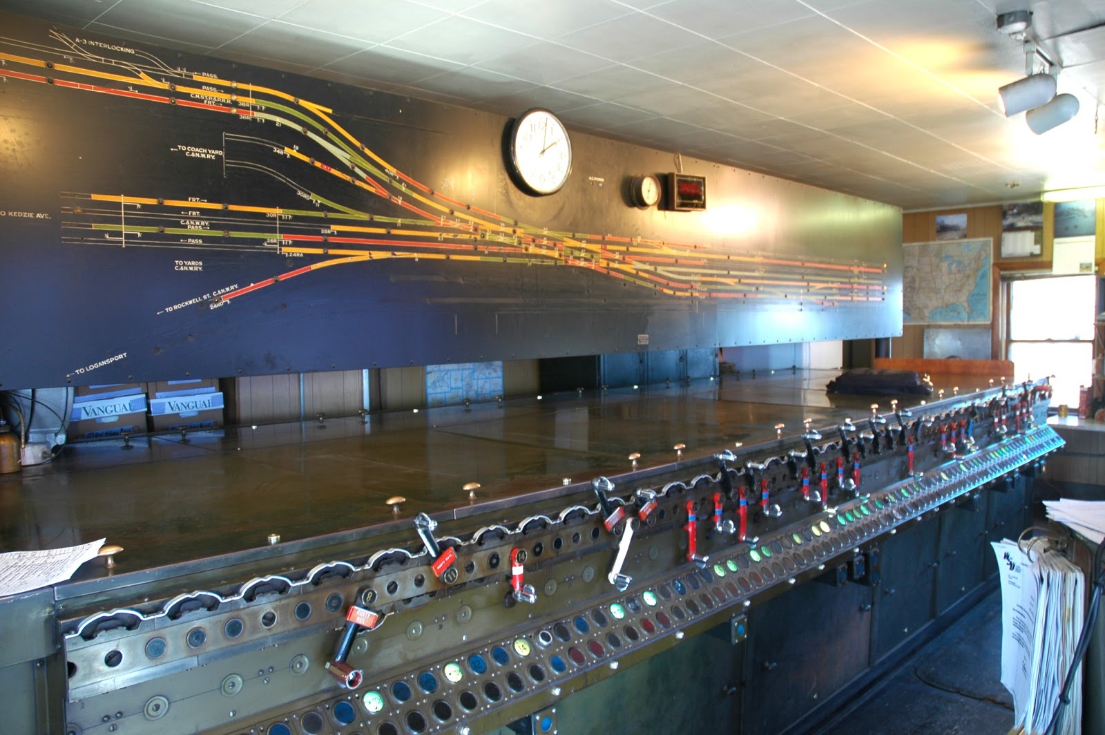
Here we see the venerable US&S Model 14 electro-pneumatic interlocking machine. This is an 83 lever frame that contained 69 active levers in its original configuration with 45 for switches, derails and movable point diamonds, 22 for signals and two release levers that I believe set traffic direction over the crossing. As this tower is following Milwaukee practice the model board is of the more colourful variety with color coded track circuits whereas PRR practice used a white on black scheme with diagram symbols to indicate circuit boundaries. The other Chicago Union Station towers, LAKE and JACKSON streets, also used this multi-colored style. Due to the four color theorem US&S only needed pastel versions of red, green, yellow and blue to represent all the circuits without having any one color touch another of the same type.
While the model board has had all of the removed trackage blacked out, those altering it did a good job blacking out what was gone and re-painting what could not be simply blacked out. Moreover all of the original text labels like C.&N.W. RY and C.M.S.P.&P. RY are still present along with the control city of Logansport on the since removed PRR Panhandle track. BTW, I believe that the model board is in fact fitted with three clocks, one old analogue, one new analogue and one digital.
Builder's plate on the Model 14 machine. Constructed in 1938 this is a fairly late model frame, although production would continue up until the 1950's.

Wider view of the Model 14 machine. You can see that when the tower was renovated it was fitted with a drop ceiling and track lights to illuminate the model board.

Opposite side angle view of the Model 14 power frame. You can see that the lever 83 position is still occupied to control a switch. Of the 69 original active levers about 45 are still in service. Those switches that do not see frequent movements are affixed with Rusty Rail tags which remind the operator that trains working over those switches may not shunt and therefore the operator should verify that the route is clear before making any conflicting actions. Probably due to a noddle incident there is now a sign on the interlocking machine advising people not to put food or drink on top of it.
As would be expected the levers at the far right of the machine handle the position light signals and crossovers in the east end of the interlocking plant. The 77 turnout is set reverse with a blocking device applied which would imply that track #2 east is out of service at that time.

Here in a closeup of levers 29 through 49 we see the standard US&S setup with switch levers pointed upwards and signal levers pointed downwards. Unlike PRR practice, the levers here have also been painted in the normal style with switched black, signals red and lock levers blue. The PRR tended to leave all of its power frame levers painted black.
The rows of indicator lamps are also in a configuration I am less familiar with. Normally these show which levers are free to move. As signals have two positions, R and L, each is shown on the indicator panel. For switches only one lamp is needed and the other space being blanked out with a "switch" label. In this case there are two full rows of lamps, one green, the other red and the switch text is marked on the green lamp. When the lever is not locked by presence of a train (TOL) the red lamp illuminates. This machine does support fleeting and when a signal is fleeted the green lamp will flash. Mounted below the indicator panel are additional lamps for the high signals that appear to show if that particular signal is available for specific routes. A quick comparison between the photos and the diagram seems to indicate that these lamps are only provided for main track signals in the standard direction of travel. The 40 lever has two of these lamps, ostensibly because track #1 is used for movements in both directions in and out of the coach yard. Finally, in place of the 44 lever position is what appears to be the button to activate the tower's alterness horn.

Let's take a quick look at the left hand side of the 4-color model board for a moment here not just to admire the remarkably preserved paint or lettering. This section of the board covers the western approaches to the plant and you can still see make out the original layout where various tracks and switches have been blanked out. Take note that the block coloring only applies to some of the approach blocks. This is because there was no apparent need to wire in trains approaching from the reverse direction on single direction lines. Today all three Milwaukee tracks are bi-directional, but no approach indication is given on #1 track (although modern trains approach from that direction would be picked up on the A-3 interlocking model board). Similarly only two of the CNW tracks have the approach circuits and like I mentioned in the last part that line is run both right handed and in 2+2 to this day. From the text labels the 2+2 running was designed for parallel freight and passenger running, but seeing as how freight trains have no need to go to downtown Chicago anymore both are used for passenger, although the old freight lines are generally assigned to deadhead stock moves during the day.
One bit to take note of is the #19 switch and derail past the 34R signal. Back in the day before the 4th track was removed there was a non-movable point diamond crossing there. That track allows trains from the CNW coach Yard to access the Milwaukee line towards Union Station. It's just one additional diamond in a plant stacked with them, but it is still significant. Also at the bottom of the board you can see all of the former PRR trackage now blacked out.

So in this picture we see the machine levers looking at a right facing angle with levers 19 through about 40 in good view. One might notice the white painted level #20 standing out from all the other red signal and black switch levers one would expect to find on a machine like this. Lever 20 is one of two "release" levers on this machine. The other is the blue painted lever #60 that can be seen a ways off down the front of the machine. So the questions are what is a release lever and why is one painted white and the other painted blue.

I had originally though these were crossing check levers, installed to provide an easy point of interlocking when you have something with as many conditionals as a diamond crossing. If you check some of my other tower posts you will find examples of these on both US&S and GRS frames. In actuality these are the machine's release timers for canceling routes and running time. The blue lever corresponds to the signal levers marked with the blue tape and the white lever corresponds to the signal levers marked with the white tape. The division is between the diamond crossing (west) part of the interlocking and the PRR crossover (east) part of the interlocking.

In this cool artsy view of the levers you can better see the blue painted 60 release lever as well as the rusty rail tagged 81 and 83 crossovers in the east end of the plant that are not used much due to duplicate crossovers being provided up to tracks at the MORGAN ST interlocking.

Moving back to the opposite end of the model board we once again look at the approach block coloring and the impact of bi-directional operation. Like the right hand side the board is painted as it was delivered with approach blocks only indicated for non-wrong rail movements. However the conversion of the now three Milwaukee Road tracks to bi-directional operation has resulted in approach indication lights being added to the black painted center track #2 and "traffic lights" being added to all three tracks. These lights indicate if a flow of traffic has been established inbound from the next controlled point, which in this case is MORGAN ST interlocking (aka RACINE) that I believe is controlled from Tower A-2 itself.
The former passenger CNW tracks are still operated in the single direction fashion, but the two former freight tracks appear to be equipped for bi-directional operation at least up to the westbound home signal, probably to facilitate off peak deadhead movements to the yard. Note the traffic lights on both tracks, but the lack of approach circuit indication on the former eastbound freight track.

In this shot we see the machine in operation with a Train Director sitting at the desk and a leverman in the process of lining a route. The Train Director also has direct control of a unit lever machine for Tower A-3 and a video display unit for MORGAN ST.

Train Director's desk showing the telephone concentrator, various other telephones, radio mic, record of train movement sheets and the Tower A-3 unit lever machine. The operator has to communicate with METRA, Canadian Pacific and Union Pacific railroads as well as Amtrak's Chicago Union Terminal dispatching center. I'll bet this is one of those jobs where you can't please all the people all the time, but as a METRA employee the Train Director only really needs to please his own bosses.
Like I mentioned before this tower seems to have gotten a real 1970's makeover with track lighting and faux wood paneling on all the walls. Also in evidence here is the break station with a microwave, toaster over and small food prep desk (hence that "no food on the machine" sign) and a large number of chairs for various tower visitors and C&S personnel.

Another close view of the Train Director's workstation and his sight lines to the model board, CCTV displays and out the bay window looking west along the CNW main line.

Here we can see both the Tower A-3 unit lever machine and the VDU for MORGAN ST interlocking. The Tower A-3 machine is pretty standard with two tows of unit levers, the top with 6 switch levers and the bottom with 4 signal levers. No signals are displayed, but a single switch is reverse. Levers are toggles that flip side to side instead of up and down. The bottom row contains miscellaneous indications like low air pressure etc. The MORGAN ST unit is a point and click video game worked from a flat panel monitor. I believe that control is from A-2, but it could be remote to somewhere else and A-2 has this display for its own information. The next interlocking east of MORGAN ST is CANAL ST, which is the new entrance to Amtrak's Chicago Union Station trackage. That used to be controlled by the old LAKE ST tower until about 5 or so years ago when it was moved inside the station to a new dispatch office.
Next to the model board you can see two CCTV displays. The first provides a view into the coach yards to alert the Train Director when a flexibly scheduled equipment move is waiting at one of the signals. The second provides a view of the eastern section of the interlocking looking east where outbound trains might stack up in the same block making it harder to see what is what simply from the model board.

We will end this trip inside Tower A-2 with a couple of shots with trains in them. The first one is taken from the external stairway showing a Union Pacific GP15AC diesel road switcher towing a METRA trainset with F40PH #143 on the front. I am unsure as to why the METRA train is getting towed, although this does happen rather frequently from other photos I have seen. It is either the F40PH suffered a failure or there is some work rule or crewing issue that makes is necessary for some dedicated yard crew to just shuttle back and forth in their own locomotive. This situation is generally only seen in conjunction with the stub-end Chicago Northwestern Terminal. The train is just about the cross the 27/29 doubleslip running in the reverse direction on the former inbound CNW freight line. If you remember the model board this track has been upgraded to bi-directional operation east of Tower A-2 for exactly this sort of movement, although he would be getting a Restricting indication on the westbound 52R dwarf signal.

In our last photo we see an outbound Milwaukee district train with MP36PH-3S #411 in the lead passing the tower on track #3. The three head searchlight signal was an upgrade from the old 40R dwarf in the same location when bi-directional operation was instituted on the MILW tracks. Again we see the signal maintainer's shop that probably spends a good deal of time keeping the 80 year old interlocking plant going. If there is one bit of good news is that the long term plans to built a new grade separated flyover here and reconfigure the A-2 interlocking plant is expected to cost several hundred million dollars and has not yet been funded to at least for the meanwhile Tower A-2 will keep on functioning like it always has.

UPDATE: In 2017 a METRA operator posted a video tour of Tower A-2. You can check it out below.
No comments:
Post a Comment