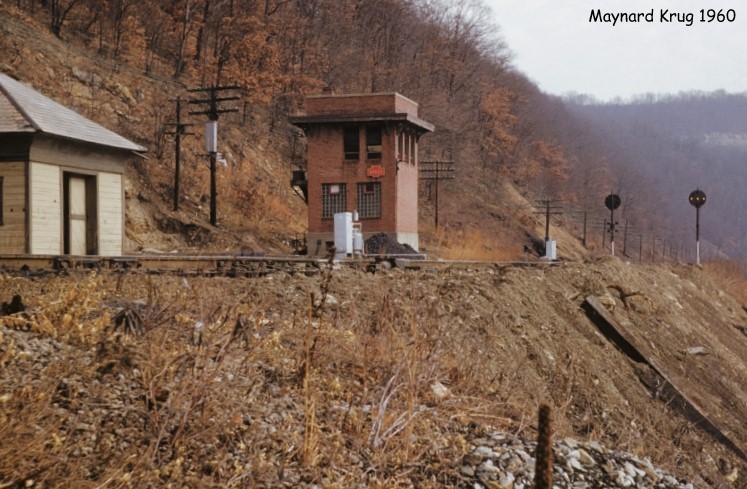
Fortunately, while searching for information on the PRR's BRADY tower on the Allegheny Valley Branch near Brady, PA, I stumbled upon a Railway Signaling Journal article on the 1944 BRADY CTC project and its use of coded track circuits, which are the same kind used in PRR/US&S cab signaling. This article not only explained why the US&S system worked the way it did, but also a number of other observations I had made over the years, such as intermediate signal locations suddenly springing to life when a route was established.
The key insight to this system is that when a track segment between two interlocking is idle, a steady flow of current is transmitted in the direction of traffic, similar to a 2600hz idle tone in old long distance trunks. Intermediate signal locations pass along this steady current until it reaches the next interlocking location that the logic interprets as the track segment being unoccupied. A request to route a train terminates the steady current at the near end and when the far end sees the energy turn off, it begins to transmit the 75, 120 or 180 pulse per minute track circuit codes we all known and love towards the near interlocking. These codes then propagate through the intermediate locations, setting the directional relays and illuminating the signal lamps and activating code generators to pass the block state on to the next signal location. When the near interlocking sees these track circuit codes it is able to display an appropriate signal.
If no following movements are planned, the near interlocking will once again transmit steady current into the track segment in the direction of traffic set by the CTC system. Intermediate signals will continue to transmit block state codes in accordance to their directional relay until they detect the steady current, at which point the directional relay is reset and the active elements of the intermediate location (signal lamps and code generators) will be turned off. Changing flow of traffic via a literal or figurative traffic lever will determine which interlocking at either end of the track segment is transmitting the steady current idle signal. This system is extra clever because in addition to not needing to transmit block state via a pole line, it is also fail-safe as any disruption in any track circuit in the track segment will register the occupancy on the CTC console.


These details explain a number of observed behaviors such as the aforementioned signal location on the US&S signaled Bessemer and Lake Erie springing to life suddenly when a route was established or the intermediates on the Port Road having the reverse direction dark. Either way it also explains why traffic control on these systems are so liable to "get stuck" and why such a situation can be a headache to resolve. Even in CTC systems where the observed behavior is different, such as continuously operating signal lamps and/or cab signal code, steady current messaging can still provide a simple mechanism to flip intermediate directional relays and establish directionality.
I urge everyone to read the primary source on this topic. It might take a few reads to get the finer points, but its leaps and bounds more approachable than the Elements of Signaling book.

No comments:
Post a Comment