In my previous post, I covered the history of NORTH PHILADELPHIA Interlocking and Tower that were constructed as part of a 1915 improvement project to build a brand new main line passenger station at what had been known as Germantown Junction on the PRR's Connecting Railway. In this follow-up article I will cover the tower itself and its interior as they stood on the eve of closure in 2005 after 90 years of service.
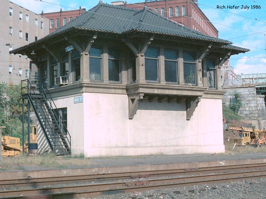
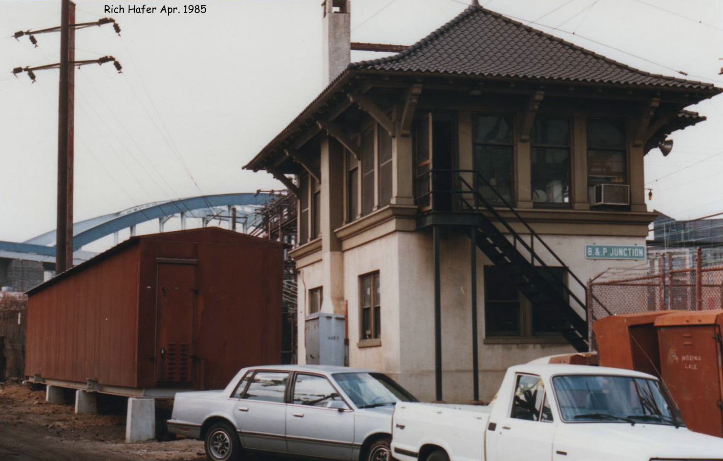
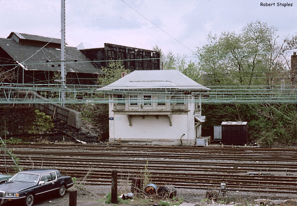
Although the adjacent North Philadelphia station itself is described as being designed in the Châteauesque style, NORTH PHILADELPHIA tower itself is more in line with UNION JCT and B&P JCT towers that were built as part of the Beaux-Arts Baltimore Penn Station project of 1911. From the outside NORTH PHILADELPHIA appeared to be an identical twin of FAIR tower located 30 miles to the north in in Trenton. However despite having been built at the same time, FAIR utilized an electro-mechanical US&S Style P interlocking machine,
an example of railroads in this period hedging their bets in regards to
purely power operated interlocking plants. Although both FAIR and NORTH PHILADELPHOIA interlockings
served stations with high level platforms, station tracks and a double
slip ladder, NORTH PHILADELPGIA would stay in service a decade longer,
despite FAIR having its Style P machine replaced by a spiffy Model 14 in
the 1930's. It would also avoid FAIR's severe case of "tower window
syndrome".

As documented in a period article in the journal Railway Signaling, NORTH PHILADELPHIA was state of the art with an all electric Union Switch and Signal Model F interlocking machine, illuminated model board and glass encased route locking cancellation timers.

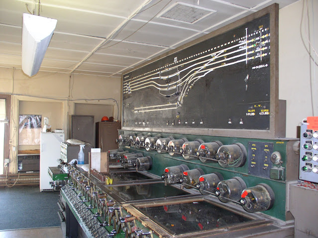
As I detailed in the previous post, NORTH PHILADELPHIA's interlocking plant would see many changes over the years, including a change from electric to pneumatic switch operation, but despite all this the tower retained its original 47-lever Model F interlocking machine. The photo below has captured the NORTH PHILADELPHIA machine in its late 90's configuration with former 0 Track at the top separated as the Conrail Trenton Line, but the other freight and station tracks still present. Also note the east end's trailing point ladder and the Chestnut Hill Branch crossover. That crossover was a later addition and we can see how it necessitated re-drawing the Chestnut Hill Branch horizontally along the bottom of the model board when comparing with the 1915 photo above. We can see the Rule 251 between here and SHORE via the 835 and 844 single direction automatic signals. Makes you wonder if an operator was ever able to arrange a movement from #1 track to #1 track via #5 track through the station. 🤣

Skipping ahead to 2005 we can really see just how much was removed before the tower was closed. Compared with the 90's photo many of the upwards pointing switch levers on the left of the machine are out of service with their numbers missing. Although similar to the more refined Model 14 in operation, NORTH PHILADELPHIA's Model F featured a glass top, to ensure the full employment of signal maintainers, and a row of cast lever indication lamps instead of the later Model 14's use of stamped sheet metal. Other changes from the 1915 depiction include the removal of the electric switch amp meter and additional rundown timers to prevent delays at peak times if routes needed to be changed. In fact the provision of a clockwork rundown timer for practically each signal lever was almost unheard of luxury in the industry, which speaks to the financial resources of the PRR. In the 2005 photo red tape with updated rundown times have been placed on the timer globes, perhaps indicating that the various signal changes on either side of the legacy plant required the times to be updated.

On the right side of the main machine we see the train announcement bell and higher numbered levers.
On the left side of the main machine we find the lower numbered levers along with the 4-lever table interlocking machine for the Chestnut Hill branch crossover supporting levers 50 through 53. Note the amount of space in this tower on either side of the lever frame which explains how FAIR tower was able to support a 75-lever Model 14 in the same physical space.

On the right side of the model board we can get a somewhat closer view of the changes that took place between 1999 and 2003. The gold stenciled labels on the board are original with the hand painted white and yellow indicating modifications. Removed portions have blacked out with paint, however most of the previous layout along with some labeling can still be seen. All four tracks to the west were bi-directional Rule 261 starting in the PRR era, but dedicated traffic levers were not provided at either NORTH PHILADELPHIA or ZOO. The red lamps at the bottom indicate which signals were currently displayed for train movements (in this case the 28R for one on track #3 west). There is also the west end low air warnings with lamps to 45psi and 20psi and a dragging equipment detector (DED) reset panel for DED's on eastbound tracks #1 and #2.

As of mid-2003 the entire east end of the plant was remoted to CTEC Section 6 as CLEARFIELD interlocking and was literally wiped off the model board despite physically occupying the same space. Because the east end no longer exists, displayed signal lamps have had the labels painted over and track indication lamps have been largely removed except approach lamps on tracks #3 and #4, which likely still give some reasonable degree of warning that a train is heading west from SHORE. Mirroring the west end we see an east end low air alarm as well as DED resets for westbound movements on tracks #3 and #4. Also missing is the 53 trailing crossover on the Chestnut Hill Branch.

The 10, 12, 14 and 16 signal levers previously controlled all main line signals through the east end and were repurposed as traffic levers as the simplest way to integrate the old 1915 mechanical interlocking logic on the west side with the modern interlocking on the east end. Observing the #14 lever lit for a westbound movement on track 3, appears that these levers must be operated for each movement, just like they had as signals, otherwise no direction of traffic is set.

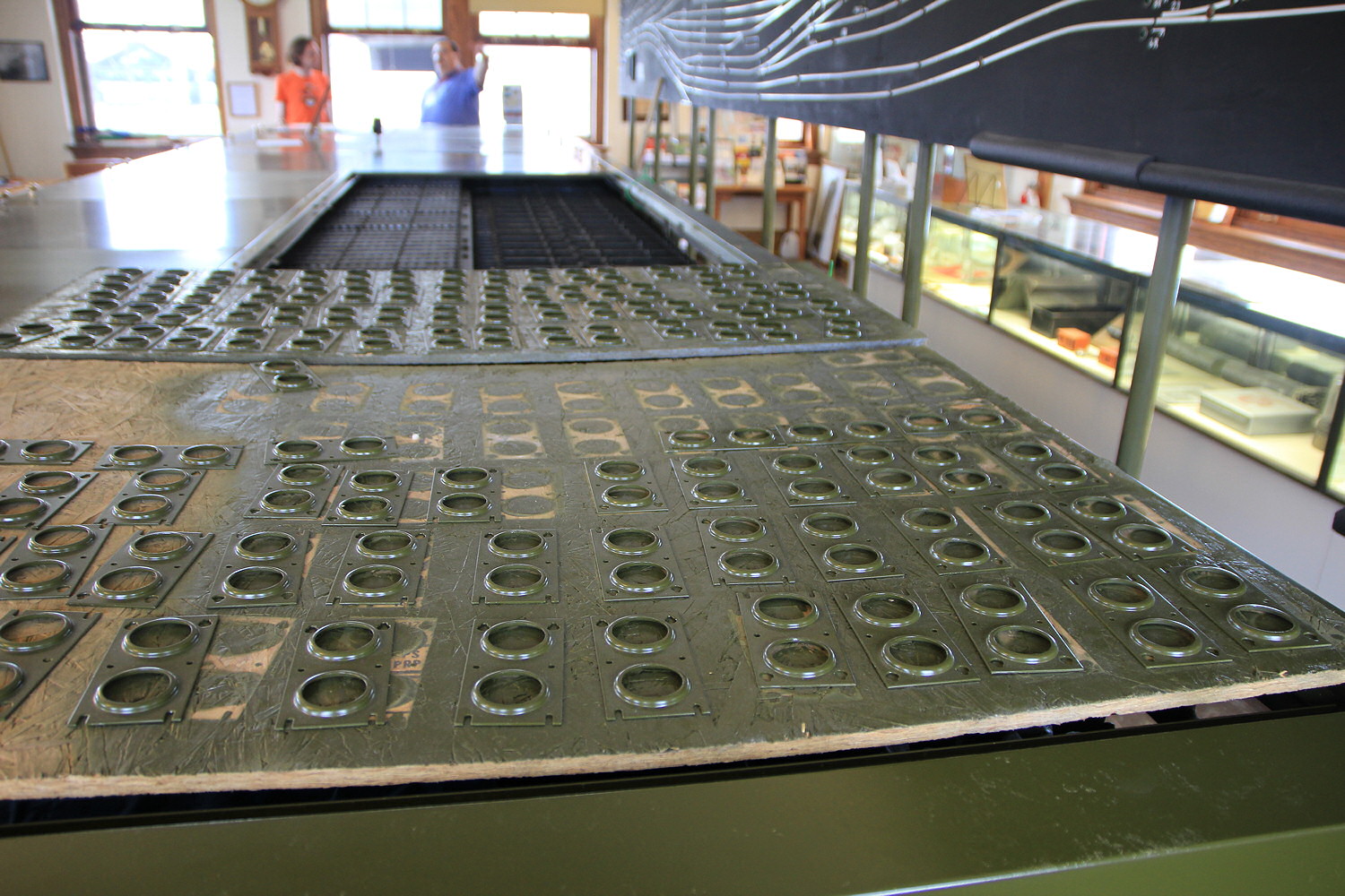
As I noted before, to the left of the Model F machine was a 4-lever US&S table interlocking machine to control a pair of signals (levers 50 and 52) and a trailing point crossover (lever 53) on the Chestnut Hill Branch. Table interlocking machines were a modular system sold by US&S that could allow for small interlockings to be controlled from a tabletop device instead of a more traditional frame that needed serious structural support. As both signals 50 and 52 would work automatically in the direction of travel and because the 53 crossover could be bypassed through alternate routing in the main part of the interlocking, there was rarely any need to touch the table machine and one can see the 53 switch is equipped with a rusty rail indication (although I believe the switch was physically removed by this point).

Each of the signal modules were fitted with a black call on button and all the active modules were fitted with indicator lamps to show status. After NORTH PHILADELPHIA closed in 2005 the 50L and 52R signals were converted into Chestnut Hill Branch automatics (plated 50CH and 52CH), however I was recently informed that this table interlocking machine may have remained in service supporting those two signals at least through 2009, arguably extending NORTH PHILADELPHIA's service life an additional few years.

Behind the interlocking machine we find the tower's internal staircase along with the exposed model board wiring and case mount for the clockwork timers and ancillary control panels. Unlike later Model 14 machines, these items are mounted directly on top of the machine about half way back instead of behind or above it.

To the right of the interlocking machine can be found equipment for the point heaters, catenary section breakers, railroad telecommunications and compressed air system. The PRR's 11kv, 25hz overhead wire electrification reached North Philadelphia, en route to Chestnut Hill (West) in 1918. This would later be extended to Trenton in 1930. I am not sure when the catenary section breaker controls were installed, but they are likely from the 1930 extension, although it can be very hard to tell without close inspection.


The operator's desk sat entirely within the large bay window along with the printer and fax machine. The size of the work area makes me think that the tower may have supported multiple crew, such as a train director and leverman, but not within recent memory according to the operator who took the photos. The large windows combined with the tower's location made this one of the most "visible" towers on the NEC and I remember being able to see the track occupancy lights on the model board when passing by on Amtrak trains after sunset.

On the operator's desk we can see the station record of train movements, radio, clock, button panel and a computer showing a CETC feed of nearby trains. Unlike current dispatching system feeds, the 1980's CETC system would drive remote terminals with a monochrome amber monitors with text lines describing various trains and a three letter reference code for the last interlocking or station they had passed. NORTH PHILADELPHIA was included as one of these points despite not being not in any way computerized as I assume CETC had visibility on track occupancy on either side of the interlocking. One of these terminals was located at the 30th St station information desk until the entire system was replaced around 2010.

The button panel contained controls for various auxiliary features, most of which I assume were inoperative. These features included the DED alarm cancellation on tracks 1 and 2, train order lights and the interlocking horn.

Mounted above the operator's desk was another PRR luxury in the form of a panel blocking device. This panel would relieve the need for the operator to apply blocking devices to select levers, instead using this panel to block out (or unblock) entire routes. As NORTH PHILADELPHIA was set up entirely in Rule 251 territory when the panel was installed, blocking was active on all tracks as any bi-directional track could be blocked via the traffic lever. To block a route with the current of traffic, the knob would be rotated 180 degrees to expose a red circular "HOLD EWD/WWD" label. To allow a route to be displayed against the current of traffic the knob would be turned to expose a red circular "MOVT EWD/WWD" label. The panel would also make circuit connections to block or allow signals to display in that direction, likely by working through the Switch/Signal protection logic. These labels can be seen on the left side of the panel that handled the westward track segment towards ZOO tower where the knobs were removed when those tracks were changed to Rule 261 operation prior to the 1960s. Eastward knobs were also likely non-functional by this point with the CLEARFIELD interlocking project and Rule 261 operation to SHORE. Chestnut Hill knobs were likely functional as that route remained under Rune 251 until the mid-2010's.

The tower's notice board was an anachronism stew with the Pointless Arrow, Conrail, the Northeast Corridor Region and Philadelphia Division all having ceased to exist by 2005.

With that we have reached the end of the tour. You can view all the photos displayed here and a few others that weren't in this gallery ( mirror ). If you missed part 1 where I discussed the physical layout of NORTH PHILADELPHIA and how that changed over time, you can find it here.

No comments:
Post a Comment