
Stop and check position of drawbridge, spring switch, derail, gates protecting railroad crossing, ensure the way is clear and drawbridge, spring switch, derails, or gates are in proper position and proceed at Restricted speed
The rule sounds simple enough, sort of splitting the difference between a Rule 292 Stop signal and a Rule 291 Stop and Proceed signal. However, to fully understand Stop and Check and the reasons for its use you have to place yourself in the context of the single line, train order based system of operation that predominated in much of North America up until the 1960's. Growing up in the Northeast with its heavily industrialized past it is easy to develop a rather bias view of what railroading should consist of. I.E. Main lines have 2 (or more) tracks, signaled with ABS and interlockings (manned or otherwise) are plentiful, especially at main line diamond crossings and movable bridges. Secondary tracks can be single and controlled by manual block or train orders, but its not such a big deal because those are the old agricultural lines that don't even exist any more. Maybe if a railroad was trying to pinch pennies that might employ something with Absolute Permissive Block with swing switched passing sidings and holdout signals, but that's more an interurban thing. This point of view would also apply in Europe.
Unfortunately this reality only existed where industrial and population conditions allowed for it as things like two track main lines and interlockings are big ticket items that railroads serving areas that consist mostly of empty land or farm fields simply could not afford. In these places the model was single track main lines with passing sidings and some bi-directional ABS if you were lucky. Interlockings were few and far between with diamond crossings and movable bridges getting no special pass on this. Oh, and trains dispatch themselves working with timetable and train order. For a system that did whatever it could to eliminate the need for full fledged interlockings, Rule 293 Stop and Check is to diamond crossings and movable bridges as spring switches and absolute automatic hold out signals are passing sidings.
Stop and Check plated signals are automatics in that there is no human that can push a button and set them to absolute Stop, yet they are attached to things that might often require an absolute stop like diamond crossings and movable bridges. However they can get away with this because what Stop and Check protects does not represent a decision point for the train. Instead of spending money to install an interlocking that must have routes set by a human and must require human intervention in case of a failure, Stop and Check allows train crews to inspect local conditions on their own and continue without external input.
Now the usefulness of Stop and Check is clear in the old Train Order days, but why would they appear on modern CTC lines? Well under early modern CTC schemes where Stop and Check is likely to appear there are several factors at play. First you'll still save money using Stop and Check than installing an interlocking. Second, the majority of railroads outside of the Northeast industrial belt did not adopt a Call-on aspect as standard in their CTC interlockings so if there was a problem affecting the ABS logic of an interlocking a signal could not be displayed even if the routing logic checked out. Passing such signals would require dispatcher intervention, which on a low density line isn't a huge problem, but the more absolute signals one installs, the greater the potential for disruption. Finally, simply fitting an old train order operation main line with CTC doesn't necessarily eliminate the old train order mentality. The line is still single track with short passing sidings. Fitting fully fledged interlockings in the space between these sidings only allows for dispatchers to screw up and create Mexican standoffs at the movable bridge or diamond crossing. Since routing decisions can only be made at passing sidings there is no reason to allow dispatchers to exercise control at intermediate points unless there is an explicit need for a holdout signal.
Alright then, I think this is a pretty good investigation of the context behind Stop and Check so let us look at a real life example located in Athens, Georgia where the CSX Abbeville (nee SAL) crosses the former Central Railroad of Georgia Athens branch crossed. Today the old CoG line is run by a shortline serving local industries north and south of the city. It sees nowhere near the level of traffic as the Abbeville Sub does and therefore there is no need for full time mediation of routes at the crossing. The crossing is also one block north of Fowler Junction passing siding and while a holdout would be appropriate here, it was not seen as necessary.
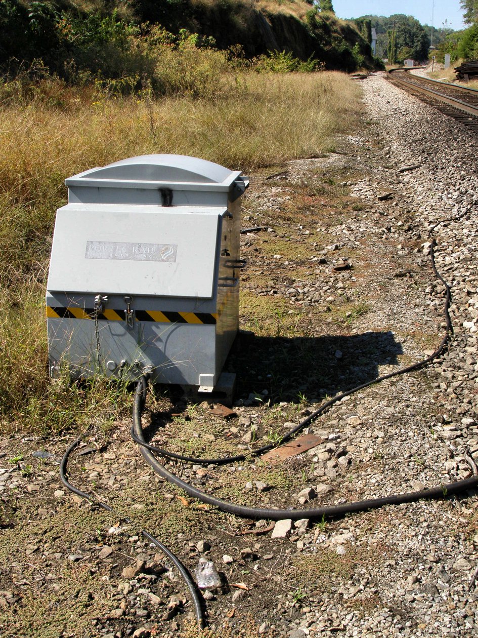
We begin looking north along the Abbeville Sub and one thing in our immediate favor is that for whatever reason these signals are not approach lit so unlike every other signal on this line we are treated to constant stream of block occupancy and direction of traffic information. Also in evidence is a solar powered rail greaser, and a call box that may or may not still be in operation. Keep in mind this is not an interlocking and as such has no station name associated with it. It's only reference in the employee timetable is on the diagram and there are no special instructions regarding a "railroad crossing at grade. So for train crews the only thing special about this location s that (C) plate.

Nothing too special about the signal except that it is a US&S model N-3 integrated color light with an "elephant ear" type backing. The signal was probably installed along with the CTC project in the 1980's and was at the tail end of the use of the classic N series signals before US&S switched to a new singleton modular unit in the 1990s. In another nod to cost savings the standard maintainer's ladder has been replaced by a set of pole affixed rungs.

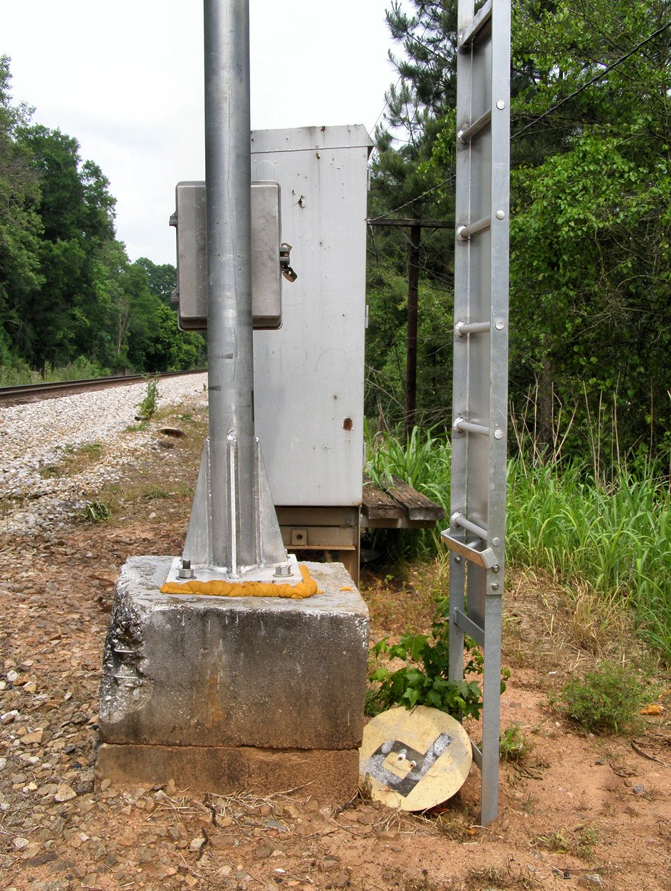
The relay box is located by the southbound mast in the southwest quadrant of the crossing. It is of the design typical to ABS signals instead of the bungalow style used for interlockings such as at nearby NE FOWLER JCT. While note the cut telecom line heading into the case which was probably used to report block state back to the dispatcher via a pole line. A similar hook up was similarly cut on the MP 511 automatic. The lack of an ACTS antenna indicates that there is no dispatcher control over anything at this crossing, however the "double wide" relay box indicates that a bit more equipment is present than usually required for a simple ABS boundary.

Looking in the southbound direction we find a much shorter and freshly painted mast protecting the crossing. The northbound signal is much taller due to the presence of a hand operated connecting track to the CoG from the Abbeville Sub in the southwest quadrant ([url]http://acm.jhu.edu/~sthurmovik/Railpics/10-10-10_ATHENS_CROSSING/CSX_Abville-Sub-5055-CoG-connector-sw-gone.html]since removed[/url]) which combined with a curve in the main line could could obstruct the view of a shorter signal.

This mast was freshly painted and was also displaying Stop. Until recently CSX had adopted the common practice of painting the "business" end of its signal masts black and the pole end silver to increase visibility of the signals. With the advent of unpainted aluminum signal structures and Darth Vader hoods this practice only continues with the remaining Conrail territory in New Jersey and Michigan. The (C) plate is made from fiberglass and is similar to the (P) boards that the Seaboard System liked to use to mark its permissive signals with.

Base of the mast showing a close view of the (C) plate, mast mounted rungs, terminal box and clamp style mounting to the concrete foundation. Also note whatever maintainer repainted this did not bother to mask the foundation.

Closeup of the signal head shows a lot of wear and tear as well as many coats of paint. The backing has also been hit by numerous BBs and .22 rounds. I guess they don't call certain signal heads "targets" for nothing. :-)

Rear view of the southbound mast. Note how the maintainer rungs are parallel to the tracks.

Getting to the diamond itself we find it is one of the new "flange riding" varieties wherein the flangeways for the track of lower importance is eliminated and instead the wheels ridden up and over the top of the rail head. While this limits the speed of crossing traffic to approximately 5-10mph, the elimination of the flangeway gaps on the main track allows for full line speed (compared to a maximum of about 40mph over a regular diamond) and much reduced maintenance costs. Here is the diamond looking southbound along the Abbeville.

And northbound.

Here are the flangeways for the former CoG track showing how the weight of the cars are carries solely by the flange over the length of the diamond. The lack of a groove cut into the top of the main line rail indicates that this diamond is relatively new or traffic over the crossing is very low.


So now its time for the big reveal to show the sort of protection afforded trains running on the former CoG line and it is climactic in the very nature of its anti-climax. You are not missing anything as there are no signals or any other interlocking appliance protecting the crossing. The only thing there are a pair of hand operated, electrically locked derail units that one can barely see.


The derails are a simple affair. Here looking at the western CoG derail we see a traditional low profile hand throw switch stand with a bolt on electric lock that manipulates a rail mounted derail that in turn is attached to a point detector unit.

Here is a different view of the east derail showing the electric lock and the rodding to the point detector. I guess the banner on top of the derail stand can be considered the CoG line's "signal". Hey, its mechanical

Position of eastern derail compared with the diamond.

And we see the same thing over on the west side only more backlit.


While walking back to my vehicle I noticed that the northbound signal for the Abbeville sub had flipped to Clear. Again the lack of approach lighting meant that the train was not imminent, only that the dispatcher had set a route for a train that would eventually show up and as I had a friend waiting back in the car I decided to leave rather than wait around.
Unfortunately I was unable to positively determine the behavior of the intermediate signals based on my observations. I suspect that in the time I was walking from the northbound to the southbound mast the dispatcher "threw traffic" and flipped which direction was getting the clear signal. However it could also be that signals at this xing stay at red in both directions until a route is aligned. Normally I would expect both signals to clear in absence of a set route, but US&S supplied systems tend to go with the whole set flow of traffic system. Anyway, here is a closeup pic of the northbound mast showing clear with the (C) plate.
Ok, enough with the photos let's finish up here by covering the procedures. For trains on the main line, if encountering a Stop and Check the train would, well Stop and a member of the crew would get out and check that both derails on the CoG line were in the derailing position before continuing on at restricted speed. For trains that know they are following another, but to shorter signal block distances it might be preferable to just wait at the signal until it changes to something more favorable. However if it doesn't change due to a track circuit failure or some other reason the stop and check procedure can be used without contacting the dispatcher.
Now for trains wishing to cross the Abbeville Sub on the CoG track the procedure probably involves calling the CSX dispatcher for permission, however this step is not necessary for safety, only a courtesy for traffic flow reasons. In fact it is entirely possible trains on the CoG have priority or some sort of negotiated priority so that they can't be left waiting indefinitely. Next the train crew would initiate some sort of timer somewhere. As we know there is no dispatcher control then the electric locks must be controlled through local signaling logic. This means there is either some sort of approach locking and the locks are only engaged when a train is approaching (unlikely) or the crews must run a timer in all situations. Running the timer would set both Stop and Check signals to Stop and Check and after 5 to 13 minutes the lock would unlock both derails allowing the crew to disengage them for passage. After the crossing is clear the crew would reset the derails. If they forget that part the next CSX train to get stopped would when reset them during the whole "check" phase of the operation.
Well I hope you enjoyed looking at yet another quirky corner of the North American railway signaling world. As always questions and comments are appreciated.
I found it a bit confusing that you refer to these signals as "automatics" using an "design typical to ABS signals" yet they can turn to green when a dispatcher locks in a CTC route. So why can't the dispatcher "push a button" and drop them to Absolute Stop at will?
ReplyDeleteAutomatic signals in CTC territory respond to the notion of a "flow of traffic". CTC means that this flow of traffic can be set centrally (that's why its called Centralized Traffic Control), however this crossing is not a control point and the dispatcher cannot command both signals to display a Stop indication (in fact they cannot even display Stop even if they wanted to) or in any other way counteract the automatic signal logic.
DeleteWhen traffic is set the signal in the direction of traffic will display block condition and the signal against flow of traffic will display Stop and Check. If traffic is not set both could display block indication or both could go to Stop and Check. Remember, all controlled signals must be able to display an absolute indication because if a train can still proceed as it can with these signals there is no point to making them controlled.
I don't know if anyone will see this since this post is so old, but I have some updated information about the operation of the CoG crossing. For one, with the 2015 re-signaling of the Abbeville which included PTC, the Athens Line (the shortline that now operated the CoG) now has signals on each side of its line. They're two-lamp Darth Vaders, displaying Red or Green, the derails are no longer used. Additionally, the CSX signals appear to be an automatic interlocking. Based on observations as well as some CSX sources, the signal of course defaults as Red. If the dispatcher has lined a route NB through NE Fowler (previous signal/control point), NE Fowler remains at approach. When the NB train is close enough, this interlocking automatically upgrades to Clear (or otherwise as appropriate), and NE Fowler also subsequently updates. Something similar should happen for SB moves, however the SB signal is much harder to observe, and the distant signal is not also a control point.
ReplyDeleteThank you so much for the update!
Delete