Anyway, 2007 was a rough year for mechanical interlocking towers in the United States with two of the 4 remaining towers with mechanically operated switches being closed. HANCOCK (featured here) closed in September and GRASSELLI Tower (2 mechanical switches and open part time) closed in November. This left RIDGLEY in Springfield, IL (1 switch) and Z tower in Keyser, WV with many switches as the only two active towers with lever operated points in all of North America. Z tower later closed in 2008 and Ridgley followed in 2010 which left no mechanically worked points in North America.
Hancock (or HO) tower was one of a string of towers along the former B&O main line between Washington and Pittsburgh, now operated by CSX. For the longest time CSX had been rather opposed to capital investment and as the year 2000 approached this ~300 mile segment of main line was still mostly single directional and hosted 7 active towers along its route, 3 being purely mechanical. In fact the segment up the Sand Patch grade between Cumbermand, MD and Connelsville, PA had the last operating Morse code telegraph line in the country, in use until about 1986.

The towers from east to west were WB (US&S Model 14, pneumatic plant with relay machines for remote interlockings), NA Cabin in Martinsburg, WV (GRS panel relay machines), W tower at West Cumbo (GRS Model 2 pistol grip), R Tower at Miller, WV (mechanical), HO tower at Hancock, WV (mechanical), Hyndman tower (mechanical, simple crossover), SA Tower at Sand Patch, PA (GRS Model 2 pistol Grip) and VI Tower at Connelsville (Relay CTC machine in yard office). Today only WB remains open, VI having closed in 2009.
R, NA, W, Hyndman and SA were closed between 2000 and 2003 in a general line upgrade to meet with increased traffic as a result of the Conrail merger. CSX has and continues to be the worst performer in terms of end-end intermodel trains with a fleet wide average speed of 22mph!! The single direction operation on much of the route was proving to be a huge bottleneck and most of the signaling dated from the 20's and was about ready to crumble into a pile of rust so it was a miracle that all of these towers survived this long.

I am not sure when HO tower was built (I am not yet a B&O guru), but it was probably on or before the 1920's probably when the line was triple tracked. It was built at the same time as its sister, R tower, just a few miles down the line. HO was of all wood construction with a band of fish scale siding. Hancock's lever frame never supported mechanical signal levers, signals being handled by some sort of subsidiary panel much in the same fashion as a US&S Style S electro-mechanical machine.
HO was treated to some sort of mid-life renovation as the current model board clearly dates from the 40's or 50's, asbestos floor tiles were installed and the second story relay room was either added or expanded. Hancock might look large from the outside, but the operator's space is actually quite cramped as the rear 2/3rds the space of the top floor is occupied by the relay room.
HO survived due to a strange combination of luck and circumstance. The segment between R Tower and Cumberland, MD (see my recent post on B&O signals) had been equipped with CTC sometime back in the 50's or 60's when the 3-track route had been condensed to 2. Hancock also looked over a small yard with a weigh scale for sand trains coming out of a nearby quarry. As HANCOCK interlocking itself was not presenting a capacity bottleneck, there was no need to spend the time / money to replace it when so many other projects were of higher priority. Still, when the line east of Hancock was re-signaled when R Tower closed the east end of the interlocking was converted to electric switch machines with colour light signals. Switch levers 1, 2, 3, 4 and 9 were connected to the electric machines and the parallel crossover operated by the 12 and 13 levers was removed.

Anyway, HANCOCK's luck ran out as the date of Sept 17th, 2007 was set for its closing. Over the summer C&S crews began to install the new equipment, including a new 3-track signal gantry, to replace the old 4-track B&O signal bridge, cutting one of the yard access tracks in the process. Word came through the railfan grapevine that one of the operator's at HANCOCK was cool with letting railfans in for photos of the soon to be closed towers and needless to say I was able to take advantage of the situation.
You are in for a real treat as I am able to present an unrestricted set of photos from my trip to and tour of HANCOCK tower.
You can find the new photos in this gallery and you can also keep reading for a rather more complete illustrated technical description of the tower.
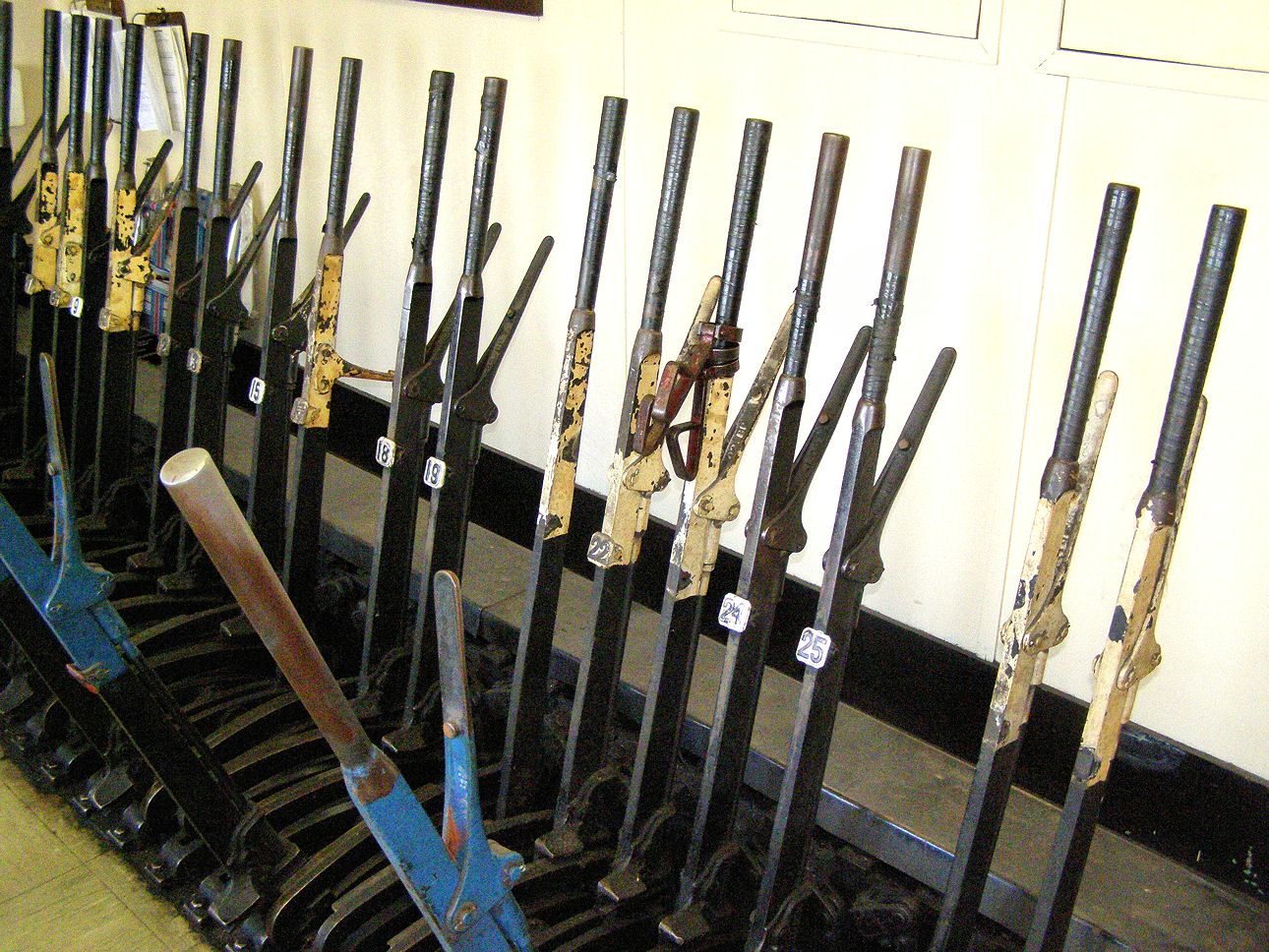
Hancock had a 28-lever mechanical frame of a design and manufacture that you all can feel free to identify. The frame consisted of the following levers:
Derail - 1
Point - 2, 4, 5, 9, 15, 18, 19, 24, 25
FPL - 3, 6, 11, 14, 20, 26
Point (made spare) - 10, 12, 13, 21, 22
FPL (made spare) 23
Spare - 7, 8, 16, 17, 27, 28

The model board also had the signal "levers" (toggle switches) on it. While the board appears to be of the General Railway Signal design, but labeld in the Union Switch and Signal fashion with the L and R terminology for signals. The 52 lever is for 2tk, the 53 for 1tk west, 55 for 1tk east, 54 for the controlled siding east and 57 for the yard tracks. The reason for splitting 1tk between two levers has to do with the original configuration when what is now 1tk was a bi-directional center track and something with the bi-directional circuitry required a separate lever.

Also visible on the model board is the remote interlocking GRASSHOPPERR HOLLOW. This was another late addition when the line was two-tracked and the old third track was truncated into a controlled siding. The 61 lever for the signals and 62 lever for the switch was installed on the model board.
Above the model board is the interlocking's only release timer. The timer is a whopping 8 minutes long(!) (on lines like these time timers are typically between 4 and 5 minutes) and it applies to every signal in the interlocking, even the yard dwarfs(!!) (which are typically only 2 minutes long). Making matters worse there is no approach locking, so any displayed signal must either be knocked down by a train or suffer the 8 minute timer penalty. This makes it virtually impossible for the operator to play around, displaying signals for the fun of it or for photo ops.

The Hancock lever frame followed standard conventions with black levers for switches, blue for facing point locks and white overpainted for spare. SOP called for the lock levers to remain in the locked position until a switch needed to be moved. Because every switch could encounter a facing point train movement every switch and turnout needed its own FPL.

The blocking devices consisted of a small metal wedge attacked to a ring. The rin would fit around the lever handle and the wedge would prevent the locking lever from being depressed. The 14 FPL lever was the only one fitted with a blocking device. The 14 locks the now non-existent 12/13 turnout so the fact that it would never need to be unlocked might prompt the operators to block it up least they break some part of the interlocking's workings. As these old interlocking age sometimes the infrequently used appliances can wear down in such a way that operating them can seize up all or part of the interlocking plant. Operators sometimes calls these "booby levers" and learning which actions can break down the plant is a key part of the tower qualification process.

Here is the model board without a route lined up. Each main track has two approach lights. The inner one indicates that the flow of traffic is set from that direction. The outer one means that a train is approaching. Trains "tap on" when they are about 3-4 blocks away and arrive about 8 minutes later. When a signal is displayed a red lamp will illuminate on all switches that are now "locked out".

Here is the model board with a route lined for 1 to 1 westbound. The 53R signal is displayed and the 4/5, 9 and 18/19 turnouts are locked out. The large knobs with the arrows are the traffic control levers. The ones on the west side of the plant are still numbered 59 and 60 and might still be active while the ones on the east side of the plant may not be. I neglected to ask the operator how the traffic knobs are used in practice, but at the very least to clear a signal the traffic needs to be aligned the proper way.

The operator informed me that in his few months on duty most of his work involved clearing signals for straight moves. One a day he would get a local freight out of the industrial track loaded with aggregate cars and that would involve reversing levers 2, 4, 5, 9, 15, 24 and 25 to move the train into the yard. He told me that the dispatcher only told him to cross mainline trains over ones every 1 to 2 weeks and there was some rust visible on the 18/19 turnout. This is not surprising given that Hancock was flanked by CTC crossovers about 7-10 miles distant in each direction which the dispatcher could operate himself. Movements into/off of the siding via the 9 switch were somewhat more common.
Hancock tower was fairly comfortable inside with your typical operator's desk (note possum calender), safety board and general storage.

Outside the tower there were two pipeline runs, east...

and west.

With the east having been severed when the east end was given electric switch machines.

The 15 switch was operated by pipes running directly out of the front of the tower. In this photo you can see the two components to each set of points. There is a rod to throw the points (Black in the tower) and another rod to lock the point as well as detect their position (Blue in the tower). This second rod is called a Facing Point Lock. The FPL lever must be throw to the unlocked position for the points to move and cannot be re-locked until the points are at one of their two standard positions. If a route is cleared over the points in question the FPL lever will not be able to be thrown.

Every pipeline was equipped with a compensator to deal with the wide range of temperatures see at Hancock.

It was interesting to see the lack of any sort of general upkeep with the pipelines. With most of the other mechanical towers in this country all of the cranks, compensators and supports were slathered in a good layer of black grease. Here it doesn't look like any of the equipment has seen a dab of grease in years.

Still, the operator told me that while the 15 switch in front of the tower was easiest to throw, even the longest pull to the 25 switch was not particularly difficult. He also wait that the 18/19 turnout was the hardest to pull, in part due to the weight of the long 30mph (#15) blades as opposed to the short 15mph (#10) blades on the yard tracks.

By the time of my visit the track into the #24 switch had been cut and the #24 switch wedged and spiked reverse to make room for the base of the new signal gantry. The pipes to the #24 switch had been disconnected at the runout cranks.

Each of the mechanically operated points had the facing point lock outside the gauge where a power operated point machine would be located normally.

The FPL was integrated with a GRS mechanical point detection unit to provide feedback to the signaling system.

The west signal gantry was a classic B&O design made from angle irons and spanned 4 tracks with B&O CPL signals. From right to left you have the 52L full speed signal on 2tk, 55L full speed signal on 1tk, 55LA medium speed signal off the siding and 55LB medium speed signal out of the yard.

Next to the gantry on another yard track was the 57L restricted speed CPL dwarf signal.

The CPL signals are approach lit, but after a train passed I was able to get some pictures of them lit up.

An interesting side note with the 57R signal, the signal was located before a hand throw switch with point detection. There was only one signal for two tracks so I assumed that the 57R governed both yard tracks moving through the interlocked 25 switch. The point detection on the hand throw was probably to make sure that the switch was in either of its positions and not half-thrown, before a signal could be displayed over it.

In the space next to the yard, the replacement turnouts were being staged. CSX currently uses US&S M3 electric point machines and these replaced the GRS Model 5 units that populated the east side of Hancock interlocking.

The story of Hancock did not have a happy ending. The tower was closed in September 2007 and the local community expressed some preservation interest. However the structure was found to have significant termite damage and the tower was ultimately demolished a year later in the fall of 2008. The story is similar to that of the old Leaning Tower of PD in Patchogue, Long Island where years of non-maintenance resulted in a structure that was ultimately unsalvageable despite efforts by the community and railroad for preservation.
I am not aware of what is to become of the lever frame and other artifacts. Surely parts will be salavged to keep other mechanical frames in operation as there are a good number still operating with entirely power operated switch plants.

Here we see HANCOCK with a westbound mixed freight headed by AC4400 #528 and a raft of light engines. (I regret not taking video of the light engines, the dark pictures don't give a good idea of how many there were)

No comments:
Post a Comment