THORN tower was built in 1938 and at the time it represented a bold form if new technology on the traditionalist Pennsylvania Railroad. The PRR had been a strong proponent of the traditional block system with Block and Interlocking Stations spaced even intervals along the line with Block Operators passing trains from one to another. As the PRR was a wealthy railroad and could afford the expense of building interlocking plants where many other railroads would make do with hand throw switches and the Automatic Block System. As the cost of technology began to drop in relation to labor Centralized Traffic Control began to be embraced by PRR rivals such as New York Central. Intended to replace train orders on long single-track lines, CTC pulse-code technology could nevertheless allow multiple interlockings of any configuration to be worked from a single location. While the PRR would continue to rely on the individual Block Station until the end, it did install several significant CTC projects with THORN being one of them.
THORN's territory stretched from MP 25.3 to MP 36.6 on the Main Line and also included the Philadelphia and Trenton Low Grade Extension between those two points as well. In addition to its own namesake interlocking, THORN had CTC control over DOWNS, GLEN and DALE interlockings to the east and CALN interlocking to the west. While today CTC implies bi-directional operation, the PRR was content to use the technology for simple remote control and most of the routes were left operating under single direction ABS.
The Penn Central era brought some minor reductions to THORN's plant with the Low Grade extension being reduced to a single bi-directional track and the line between GLEN and PAOLI being reduced from 4 tracks to 3, with the center track being bi-directional.


Under Amtrak the plant shrank further with the Low Grade Extension being completely abandoned, the Thorndale yard being almost completely removed and the 3rd track between GLEN and PAOLI being ripped out due to the loss of through freight service on the Main Line in the early 1980's. However most of the interlocking layouts were kept the same due to the costs involved with modifying the logic. Here is how the territory looked in 1992.


In 1994 the closure of Paoli Shoppes due to massive PCB comtamination forced SEPTA to build a new terminal Yard in Frazer, PA for its popular R5 commuter service. This added a simple interlocking for trains to enter/exit the yard and to turn back just east of GLEN intelrocking. The old DALE interlocking, now little more than a Control Point was eliminated and the few local freight accessing the Main Line would queue up at the home signal at GLEN.
While even more changes are planned for the Harrisburg Line, in 2010 THORN and its territory are much the same as they were in 2005 when I was able to commission a survey of the tower and its interlocking plant. Some of the photos had to sit on ice for a few years, but they have been recently processed and posted for you all to enjoy. Photos that were releasable at the time were processed at a lower resolution due to the conventions of screen sizes and internet connectivity at the time.
THORN tower is an identical twin to the previously discussed COLA tower, which like THORN was a PRR CTC tower built in 1937. Both these towers were built in conjunction with the electrification of the PRR Main and Low Grade freight lines to Harrisburg. It is a two story brick building with no trademark bay window. It could be considered a forerunner of the 1940's towers built up and down the Northeast Corridor and discussed in the signalbox.org overseas section. The tower has a number of subtle art deco flourishes as well as a pair of interlocking illumination floodlights (one currently active). Also on the right side of the tower note the tower emergency horn which, in theory, can be used to stop trains moving through the plant.

The windows have all been replaced with modern types as this tower post-dates the large floor to ceiling windows that were so often butchered in modernization efforts. In 2005 a new backup diesel generator had been installed to provide interruptions to the local main grid.

Here is the east side of the tower showing the canopied entrance, Bilco doors to the basement and the operator's car.

Behind the tower we find the air plant consisting of three large kettle tanks and an old time drying unit.

This has been supplemented with a newer model air dryer with a relief hose that can be used by mischievous railroad employees to soak co-workers.

In front we find the tap to the large diameter air line that powers the point machines for 10 sets of crossovers.

Taps to the points run hidden under the ballast.

Piled in front of the tower we find some spare air hose and a pile of cast iron covers to the model CP pneumatic valve units along size an electric switch lock.

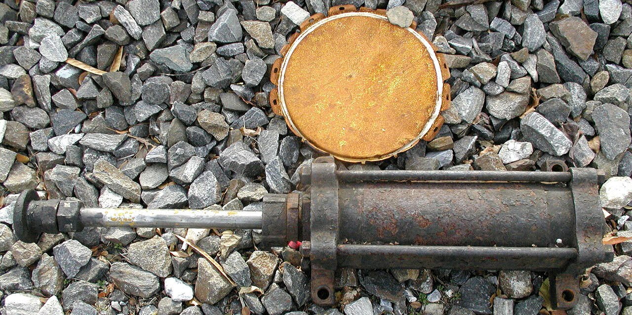
Discarded on the ballast was also a pneumatic piston unit for a US&S model A-5 point machine in the extended position.
Moving inside the tower we see the stairway to the operator's room. The large brick-tiles on the walls are a stable of schools and other institutional buildings built between the 1930's and 1960's.

On the back wall we have the signalman's lockers behind the olive green CTC console in the middle of the room. Behind the mop and bucket is the bathroom. The red-cabinet contains an emergency stretcher that can be used by third trick signalman for naps.

In the bathroom the sink is definitely original, but the toilet does not look period. The roll of toilet paper seems to hang in a somewhat awkward position.

Moving clockwise from the bathroom we find the THORN Electric Traction power board. This opens and closes the individual overhead 12Kv 25Hz catenary sections in and around THORN interlocking. All of the active circuits appear to be closed.

In the left front corner we find the mandatory American Flag along with a pair of Bell phones and the fax machine. THORN has two landlines, one each for the Philadelphia and Lancaster area codes, as the tower sits on the Area code boundary and the PRR wanted to avoid long distance phone charges. The windows here look to be original and have grown a nasty coating of filth since their last cleaning decades ago.

Here we see the front wall of the tower and the rear of the 1994 FRAZER interlocking panel.

Completing the circle we see the railroad notice board and the door to the signalman's area.

The notice board is rather out of date with the Philadelphia and Baltimore Divisions being merged into the Mid-Atlantic division and the New York division being re-named the Metropolitan Division.

Finally behind the door we find the food storage and preparation units along with a chilled water dispenser.

The centerpiece of the operator's room is of course the US&S Centralized Traffic Control machine installed in the middle of the room. It consists of a single unit with three sub-panels arranged in a shallow U around the operator's desk. The model board contains three types of indicator lamps, orange for track occupancy, blue for traffic direction, white for DED alarms and red for overhead wire section restrictions (those are non-interlocked and switched on by the operator as a reminder to where the catenary is out of service). Unlike some other types of US&S model board, such as the one installed in OVERBROOK tower, there are no green lamps indicating when a signal is displayed.
Here we see the west end of THORN's territory on the panel to the operator's left. This section contains the lowest lever numbers which belong to CALN interlocking at the former west end of Thorndale yard. In 2005 this interlocking was only in service on tracks 1 and 2 and served as a facing point ladder for westbound trains to access the remaining storage tracks. It also created a useful bi-directional siding between THORN and CALN interlockings where local trains could be turned and held clear of express Amtrak trains on the main track.
Track 2 heading west continued on to PARK interlocking which was normally not open as a block station and switched into Automatic mode. Formerly used by freight trains departing the main at PARK for the Atglen and Susquehanna Low Grade Line, it only saw a nightly local freight heading to an industrial estate west of PARK interlocking. The operator at THORN could indirectly control the signal at PARK by setting traffic on #2 track which would cause the auto-routing at PARK to display the signal to correspond with the direction of traffic. Track #2 has since been removed and replaced by a hand-throw switch just east of PARK interlocking, but the signaling was not altered and the home signals at PARK is still controlled in this manner.
After an operator at THORN accidentally routed a passenger train into #5 Running track (a track not fit for passenger movements), a fuse was removed to prevent any signal from being displayed into that track. All movements into #5 Running most be given permission past a Stop signal. We can also see the two lowest numbered levers, 3 and 4, which used to unlock hand throw trailing point industrial switches on #1 track. In most CTC systems this function is typically left in the hands of a crew operable timer outside of interlocking limits.

Also in this photo are both the old telephone concentrators. The plug-in patch box on the left of the panel has been replaced by the "newer" 1970's unit on the desk. This unit provides lines to the adjacent towers PARK (or CORK when PARK is closed) and PAOLI as well as Frazer yard and the Gap siding. There also appears to be a line to THORN itself, but I think that is the line to the dispatcher in Philadelphia. The push to talk mic and the squawk box are for radio communications to the trains. The system still works like a typical block phone, which is more like an intercom than a traditional phone system. An operator who is busy with a train or another caller can often ignore the block phone. If the call is particularly urgent then the caller can use the bell phone, but operators have been known to take the receiver off hook and leave it on the table until they are free to respond. This old concentrator was replaced around 2005 with this new one.

Moving to the center panel we see THORN interlocking proper on the left and DOWNS on the right. Below each discrete field interlocking we see a small box with various alarms, specifically low air pressure for the point machines, A/C power off and the emergency horn button. There is also a small voltmeter which indicates the condition of the code line to the field station. THORN interlocking is actually under direct wire control instead of CTC and this leads to some slight differences in how one operates the machine. A large 1950's style General Electric clock reminds the operator of the constant march of time and on top of the CTC cabinet we see the Rusty Rail notice board and various cleaning and personal hygiene items.

The only occupancy light is on #3 track between DOWNS and THORN and if this is actually a train or track car it would be one of the last to use the route as track #3 was placed out of service soon after. Track #3 has since been torn out with track #2 being placed out of service.

Finally we see the left side of the panel which features GLEN and the since removed DALE interlockings. The original terminus of the Trenton Cutoff was GLEN, but around 1906 the freight line was extended to Thorndale on an alignment that bypassed several steep grades on the Main Line. The original route to GLEN branched off at DALE, but with the end of main line freight operations on the former PRR electrified territory in 1981 the low grade extension was abandoned. DALE lingered on as a controlled signal "gateway" between Amtrak and Conrail territories, but this too was removed as unnecessary after 1992. In 1994 SEPTA built a new yard and maintenance facility at Frazer which utilized the bi-directional #2 track for deadhead movements between the yard's back door and the R5 service's terminal at either Downingtown or Thorndale.
Note all of the black paint over the 2-track Low Grade line and two of the 4 tracks that used to run east of GLEN. Also note the flyover at Whitford.

So that is the general overview of the CTC machine, now we can dive a little deeper. Unlike many CTC panels THORN has quite a menagerie of functions that were both installed new and added over the machine's 7 decades of service. One of the original features were catenary section breaker levers. Under the original PRR system the catenary section breakers were housed in the interlocking towers. Later Amtrak centralized most of these functions, but the line between just east of THORN interlocking and Harrisburg was never upgraded leaving it in its near original 1939 state. THORN was built with the electrification project and while the local interlocking had a breaker board installed right in the tower, the remote interlockings had section breaker toggles installed right on the CTC panel. Here are the toggle sections for CALN interlocking. The numbers correspond to the section designations, not the panel lever numbers. I believe they refer to the tracks covered by the catenary section. At this time all of the sections except 43 are closed, while those that covered tracks in the freight yard and the old #3 track have been removed.

Looking at the section controlling CALN interlocking we find active toggles controlling 3 points and 4 signals. Two of the points have Rusty Rail tags on them which remind the operator that trains over those switches might not shunt the track circuit and he must ensure that there is nothing on the track before clearing a route over those reversed points. The red lamp over the signal levers is not to indicate that they are locked out, but simply that the signal is not displayed. This light will flash if a timer needs to be run. On the far right we see a toggle modified to activate point heaters and a traffic indication that I am not sure what it refers to.
Above the toggles are non-interlocked switches for non-vital functions such as the red overhead power restriction lamps and to silence the activation alarms for the Dragging Equipment Detectors eastbound on 1 and 2 tracks.

Looking at the THORN portion of the model board we see the 6-track full crossover with two of the 6 tracks westbound being stubs (6 and 3) and 5 track being a non-bonded storage track. On the left part of the panel we see two traffic control buttons installed in the Amtrak era to set traffic on the bi-directional #2 track between THORN and CALN (black label) and CALN and PARK (red label). Signals are normally paired in the traditional US&S "Left" and "Right' fashion, but an additional interlocked dump siding on #4 track that has since been removed caused a mismatch between signal pairs as 60L governed movements off the siding giving 58 only a Right signal. SEPTA trains terminating at THORN will normally cross from track 4 to track 1, platform and change ends before heading back east. Sometimes if there is conflicting traffic the trains will discharge on the track #4 low level platform, then reverse onto track #2's eastern stub, then reverse again back to the high level platform on track #1.
Only three of the 10 point levers have managed to avoid the Rusty Rail tags. I mentioned that THORN was under direct wire control instead of CTC control and one difference is that for THORN the points are fitted with lockout lamps. The red lamp above the point lever indicates that the points are locked out and not free to be thrown. In this case 41 and 43 points are locked out even thought no signals are displayed. This is possibly due to the canceling of a route displayed as a test example for the photographer.

I this point I will explain a bit about the layout of a US&S CTC machine. The top row are simple switches for non-vital functions such as train order lights and alarm canceling. Next are the row of point toggles, then signal toggles. Below that are call-on buttons to display a restricting signal when there is a shunt within the interlocking limits and finally there are a row of code buttons which for remote stations command the CTC machine to send the commands to the vital interlocking hardware in the field.
Operation for a CTC site is simple. You set the points and signals in any order then hit one of the code buttons for that interlocking. The CTC machine then chunks away sending pulse codes to the remote station and when it hears back the new state the signal will hopefully show as displayed. Unsafe operations simply will not go through. For an example of how to operate a US&S style CTC machine I refer you to this video.
Now as I said THORN interlocking is direct wired to relay interlocking logic in the tower and possibly the CTC cabinet itself. Direct wire connections work differently and have been known to get operators in trouble. Instead of needing to hit the code button, actions will take effect immediately so flipping a signal lever will command that signal to display w/o needing to "confirm" the action via the code button. If an operator throws some switches, toggles the signal then throws more switches, the second batch of switches might become locked out by the signal immediately displaying and not throw. This can lead to mis-routings and can become especially problematic if giving permission past a stop signal. The code buttons are needed for some actions and the combination of some actions taking effect immediately and others requiring the code button to be pressed requires the operator to act thoughtfully and double check his work.


Levers 49 through 60 with a pair of point heater toggles between the two banks of signal levers. You can see how the blocking devices function. A metal tag fits in slots provided on the front of the CTC panel. Small pegs are then fitted in one or two of three positions to block the movement of the toggle. A single pin in the middle blocks a set of points normal or reverse. A pin in a side hole will block the signal from being displayed.

Looking at Levers 69-74 we see three switches for train order lamps placed on the 54L, 56L and 58L signals as well as the switch for the interlocking lamp on the front of the tower. I doubt the TO lamps are used any more and they probably don't work. While Form D's are still sometimes passed to trains for wrong direction operation, the operator will inform the train over the radio of any need to reach for the hoop.

Looking at the DOWNS section of the panel we see a little action as a freight train approaches on track #4 with the 76L signal displayed. Note how overloaded the 76L signal is with 3 additional instances for movements off siding tracks within DOWNS interlocking. Those tracks are unlocked by the 75 lever and I assume there is some sort of logic to make sure only one of those displays based on the position of various hand operated points.
We also have a non-rusty rail example of blocking devices with the 72 signal blocked to stop and the 71 points blocked normal. This is due to both 2 and 3 track being out of service. There are more overhead catenary section breakers and this time you can match the numbers on the toggles to the numbers on the model board outlines by small white boxes on the tracks. Only section 23 over 33 track is open. Because the Main Line between DOWNS and GLEN was made 3-track in the 1960's it actually got a traffic control lever (#74) instead of some ad hoc button. Also when the low grade extension was single tracked the lamps over the removed track were removed from the model board instead of being left dead in place.
For a little historical context the original point of DOWNS Interlocking was to provide a crossover for passenger trains operating on the center tracks to move to the outer tracks to avoid conflicting with freight trains heading off the Low Grade at THORN.

Finally we reach GLEN interlocking on the right side of the panel. This is just a Y interlocking that allows freight trains from the Dale Secondary onto track 4 and 2 westbound. Track 2 continues on into the west end of Frazer yard. It used to continue through to PAOLI, but this was removed in the 1980's as a cost saving measure that has resulted in a bottleneck between the end of the 4-track segment at PAOLI and the yard at Frazer. As I mentioned before the short segment between GLEN and DALE went out around 1994 so freight trains show up with little fanfare. The Dale secondary has had black dashes added to it to indicate it is non-track circuited.
Note all of the DED alarm cancel switches for signals 112 and 104. The PRR was good about interlocking their dragging equipment detectors to drop the next home signal.

We see another example of blocking devices on the 99 and 103 switches which are being held normal. This is because the Norfolk Southern Dale Secondary is under DCS Rules and routes into it must be blocked out unless the operator has permission from the NS Dispatcher to send a train.

At this point I will admit to repeatedly erring by referring to the signalman at THORN as an Operator. Technically the position is a Train Director and the reason is the FRAZER interlocking panel. In 1994 when the SEPTA R5 terminal was moved from PAOLI to the new Frazer yard, a new turnback and interlocking needed to be built. The Union said that if remote control was given to PAOLI tower there would need to be a second person hired to handle the workload. Amtrak reached a compromise in which control was given to THORN and the position there was upgraded from Operator to Train Director, which pays a buck or two more an hour.
FRAZER is the standard type of remote interlocking panel installed by Amtrak in the 80's and 90's with similar examples in service at STATE, PAOLI and ZOO. It uses some sort of basic digital modem technology to relay requests and state. FRAZER interlocking consists of one interlocked yard lead, one interlocked storage track and a turnback track with a holding pocket. The panel is not NX and requires points to be set manually. The large buttons are for signals and are pressed in to request a display. They are twisted one direction and pressed to fleet and the opposite direction and pressed for a call-on. The small buttons are blocking devices. They are pulled out to block a section of track from having a route set across it. The blocking buttons will also cut power to the points in the field, even if they are out of correspondence so operators must be careful to make sure the points have locked before blocking and giving permission past the stop.
Here we see a SEPTA MU train pulling into the yard from #4 track. The indicator lamp colors hold the same meaning as they do on the CTC machine. Also note the east to follow instructions for resetting a defect alarm.

Closeup of the panel.

Speaking of defect detectors, THORN also has a number of Hotbox Detector units that date from the 1940's or 50's. eastbound on #1 track just prior to FRAZER interlocking there is an HBD-DED registering on a readout to the right of the CTC machine below the Frazer panel. West of CALN there are HBD's on both track #2 and #4 reading out on stacked units to the left of the CTC machine.
These were made by the Servo Corporation of America under the Servograph brand and record the readings on a long roll of thermal graph paper. Westbound I believe the HBD is interlocked with PARK's home signals which will stop the train. If PARK is not open the crew will call THORN who will provide the readout and restore the signals. Here we see the upper portion of the HBD readout stack with the PARK signal alarm panel and the #2 track readout.

Here is the #4 track readout.

And a closeup of one of the readout paper rolls. Each spike is an axle temp reading. A tall spike would represent a hot axle box. There are instructions for the operator to follow re evaluating the magnitude of a spike to see if an alarm is valid.

This is all I have covering the the tower and what is inside the tower. Stay tuned for Part 2 where I will explore THORN Interlocking outside the tower including some interesting movements and the state of the physical plant.
A number of photos on this page have broken links.
ReplyDeleteFixed! Thank you for reporting the problem.
DeleteLooks like the photo have broken links again.
ReplyDeleteYeah, like I said my hosting caught fire, although it might be back by the end of the week. Long story short these photos in particular need to be re-processed and possibly substituted. That is why I am able to fix most of the other pages more easily.
DeleteSorry, I missed your comment at the top of the page about the hosting problem. Hopefully you will be able to restore/replace everything.
ReplyDeleteRest assured, everything will return. I have already restored most of the critical pages and am working on the rest. Hopefully the problem will be resolved this month.
Delete