So once again I will be referring to this track diagram dating from 1992. Despite being almost 20 years old it is still an accurate reflection of the state of THORN interlocking.
https://www.redoveryellow.com/position-light/Amt_Diagrams/C-7.GIF
As I mentioned before in my previous post THORN interlocking proper was a 6-track full crossover located at MP 35.0 on the old PRR Main Line that originally consisted of 4 main line through tracks, 2 tracks of the Philadelphia and Trenton low grade freight line to the east and two tracks into Thorndale yard to the west. The last major change to the plant occurred when the P&T was reduced to a single track which changed the 53 switch from a crossover to a turnout. Since that time as the P&T and thorn yard were further abandoned the disused tracks were simply stubbed out to avoid costly changes to the interlocking plant.
In 2010 track #3 is a stub on both sides of the interlocking along with track 5 to the east. Track 6 to the west still has space to store MoW vehicles and #5 Running is also still in place. Track #2 to the east is out of service past the old P&T flyover, but the tracks are still in place.
To set the stage I will start us off with some video. Here is a rear facing view from an Eastbound Amtrak train traveling on track 1 through THORN interlocking. The video starts in the middle of thorn yard and continues through the interlocking, under the P&T flyover and then through the overhead power phase break that divided the Harrisburg power dispatch zone from the Philadelphia zone. Track #2 through between CALN and THORN through Thorn yard is active and is sometimes used as a pocket to hold SEPTA commuter trains or the odd local freight clear of the main. The train is traveling at about 90 mph and you can see the fairly new Thorndale station with its full length high level platform, the three track eastbound high signal gantry, the full 6-track crossover, MoW equipment stored on the #6 track stub, THORN tower itself, the silver painted air line for the 43 switch, the reverse direction position light "pot" signals, the P&T flyover and finally the Thorndale substation and phase break.
In the next video we have the opposite rear view from a westbound train traveling on Track #4. Here we see the removed #3 track, the abandoned P&T ramp to the flyover, the two track high signal gantry on #3 and #4 tracks, the mast mounted signal for the P&T, THORN tower and the air line, the reverse direction position light pot signals, the low level Thorndale platform, thorn yard ad finally what used to be CALN interlocking which is no longer in service on #4 track.
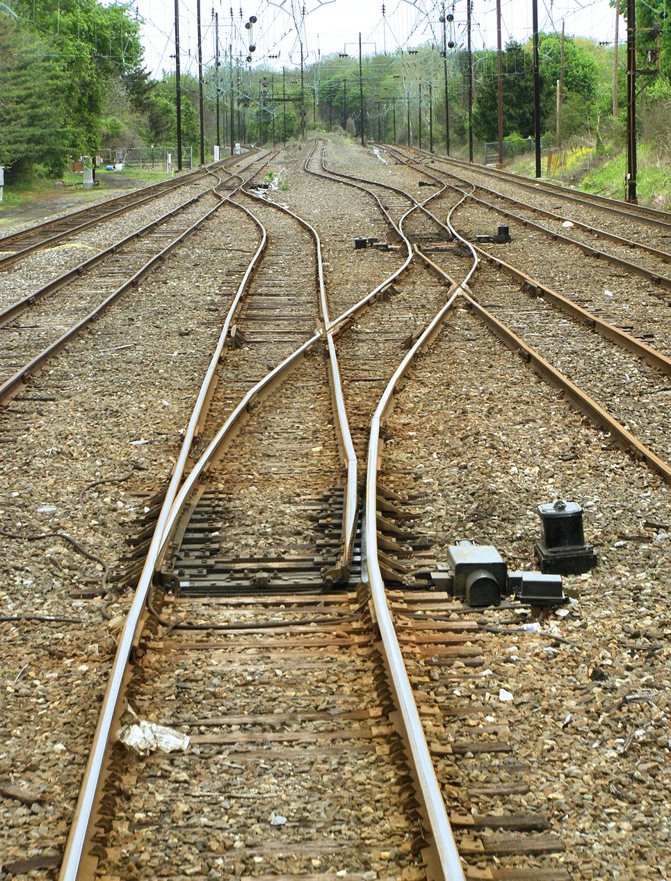
Alrighty, with the videos out of the way let us look back at an earlier trip where a train wasn't just passing through THORN interlocking on a straight route. If you remember my multi-part PRR Main Line survey my train was wrong railing between PAOLI and THORN so here are some photos from that trip that show a full traverse of the 6-track crossover from track 1 to track 4 eastbound.
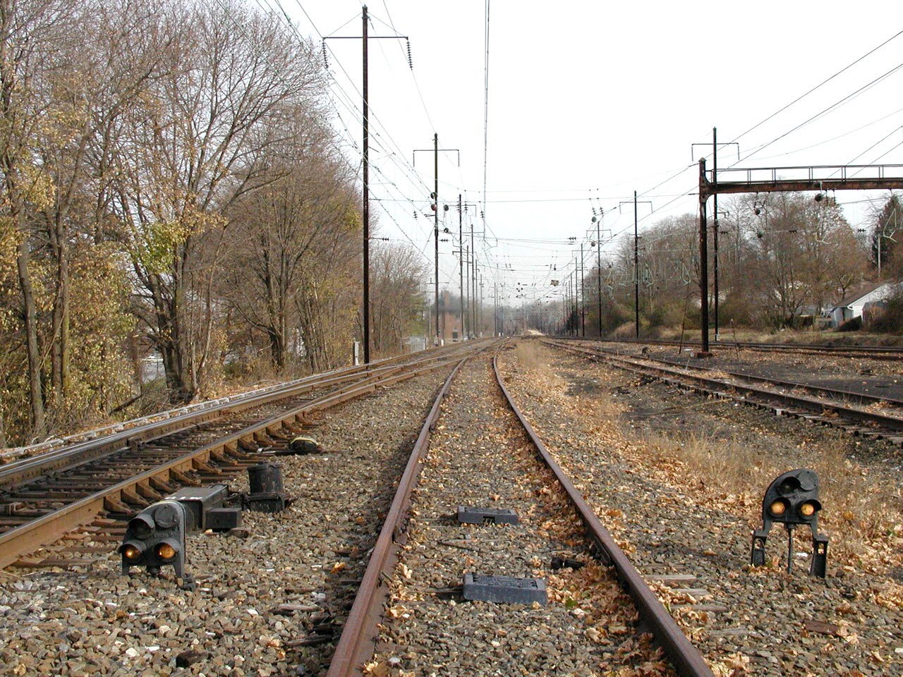
We start with the P&T flyover showing the barricade on #2 track. The in service stub is used to turn or store trains.

Next we see the rear of the 58L, 56L and 48L high signals for westbound movements. Only the 58L still governs traffic. Train order lamps are next to the upper heads.

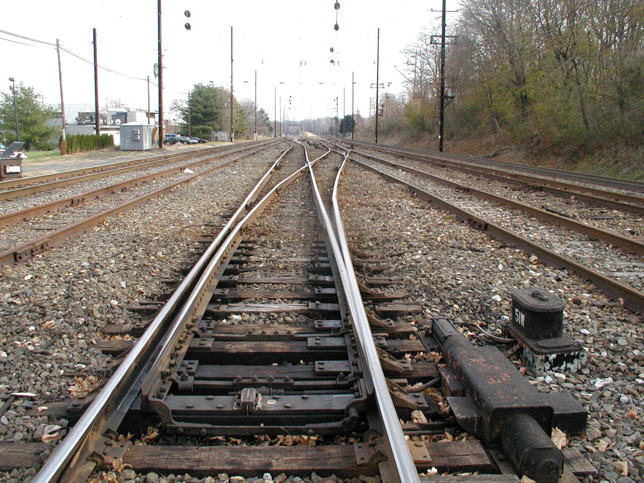
We begin our crossover by traversing the 43 and 45 switches, set reverse. The 43 switch is a bit offset from the 57 between tracks 3 and 4 so the air-line for the pneumatic points crosses over to be next to track #2. Note the single P&T track that has been stubbed at the home signal since about the early 1980's.

A better view of the reversed 45 switch.

The 45 and 51 switches reverse.

The reverse 51 switch showing the missing turnout on the 53 switch.
The 51 switch reverse with the normal 49 switch.

The 49 switch and the 55 switch reverse with THORN tower.

Reverse 55 switch.

Reverse 55 switch and 61 switches along with milepost 35.

Finally the reverse 61 switch and 60R PL dwarf signal.


And the three eastbound high signals, 44R, 46R and 48R.

Here are a pair of pictures taken back in 2002 from a local commuter train making the move eastbound from track 4 to track 1 to platform and turn at the high level platform. You can see how not much has changed


Now let's go down on the ground for a closer look from a signal maintainer's point of view with some more of those photos I had commissioned.
I mentioned several times that THORN used pneumatic point machines and here is an example of such. This is the 41E switch and its US&S Model A-5 point machine. We can see the air cylinder attached to the model CP valve unit that takes electrical signals from the interlocking plant and opens a value to the pneumatic piston. The thick bundle from the CP unit to the main body of the A-5 are the circuit connections for the point detection. The long snaky tube is a replacement air hose back to the main air line. These were originally fixed metal pipes, but this one had to be replaced at some point.

Same thing for the 41W switch. Again we see the fat pneumatic cylinder which contrasts with a longer, thinner model that also exists.

The 47E switch points showing how only the crossing over route has any amount of shininess on the rails.

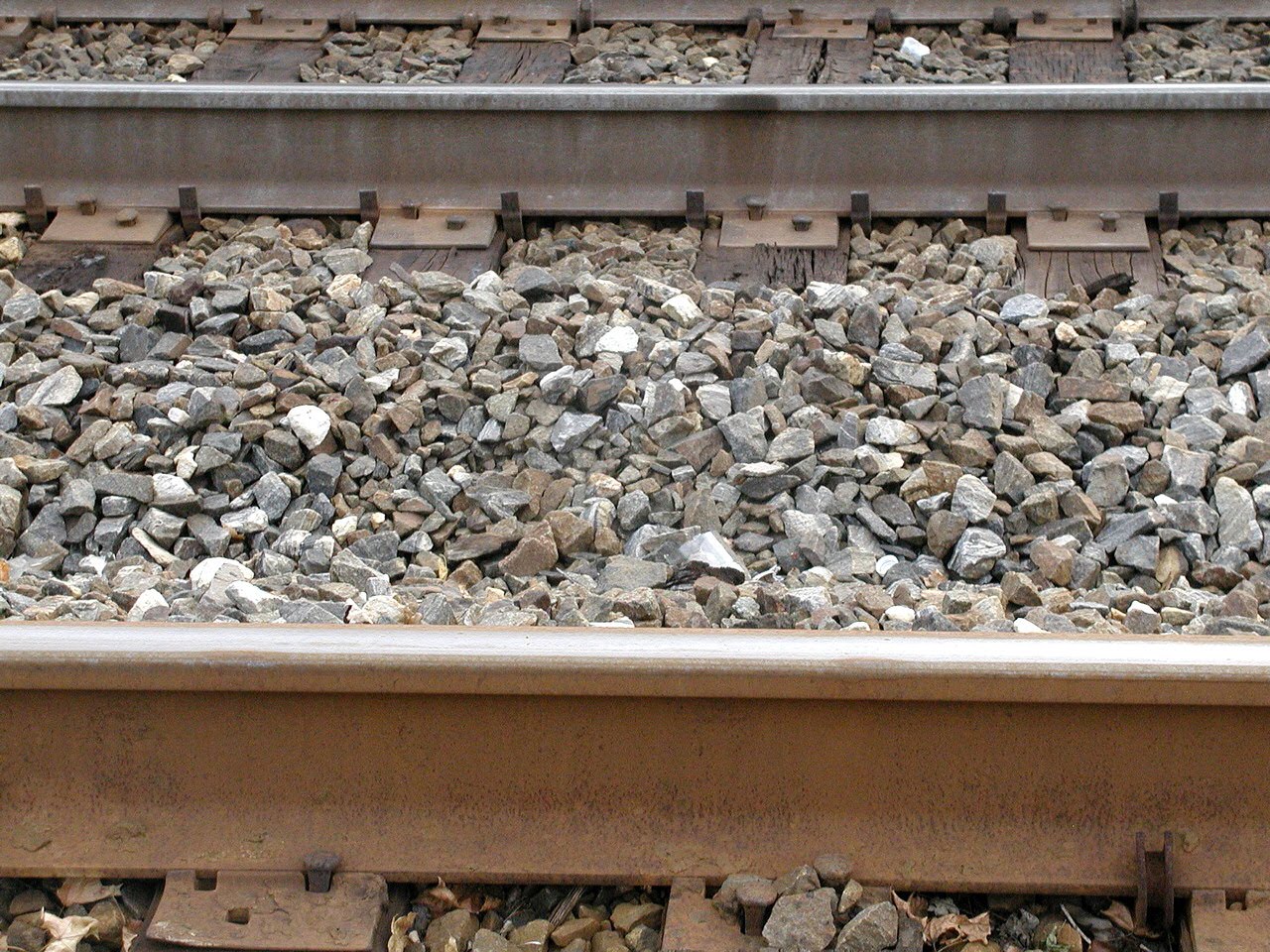
At this point I should mention something about the rail found in THORN interlocking. The Pennsylvania Railroad fashioned itself as the Standard Railroad of the World and this meant in part that it would run by its own standard equipment. So instead of using the standard rail weights of the day the PRR decided that its high density operations called for an extra heavy "Pennsylvania Special" weight of rail. So instead of the more typical 130 lb/yard tail, the PRR installed 152 and later 155 lb/yard rail. Most of this rail has long since been removed, even on most portions of the Harrisburg Line which had miles of jointed PRR rail in service through 2005, however THORN interlocking and its long out of service tracks serves as a sanctuary for this PRR artifact.
Here is some 155lb rail on one of the interlocking tracks.


Here is a 155lb splice bar with 6 bolts. Look at that joint, I doubt you could fit a piece of paper in there. Shows one the standard to which jointed rail could be maintained.

What was perhaps more amazing was the welded rail on man track #1 was constructed from 152lb segments! You can see the differences and similarities between jointed track 2 and welded track 1. Look at how tall the web is on both of them!!
Anyway, returning to point machines here we see the 49 switch looking west.

Closeup of the A-5 machine. The throw bars are on the right, the detector bars on the left.

The #51 switch looking east.
Here is a closer closeup of a CP value unit and how it connects to a pneumatic piston. The single acting pneumatic piston had a air point at each end and adding air to one side of the other causes it to move. Also note the original style under ballast metal supply pipe.

Here is a shot of a tap from the main air line that heads to the CP valve in the middle of the interlocking plant.

The 55 and 61 point machines are starting to get overtaken by rust and leaves.


Here are the 60R and 56R pot signals for eastbound movements on tracks 3 and 4.
Closeup of 56R displaying stop.

And the 60R displaying Restricting. Not many trains ever get this signal displayed so I think it may have been some sort of special test

60R signal with the 61W point machine.

Oh wow, something crazy is about to go down as here we see all three eastbound high signals displaying proceed indications. We have the 44R with a Slow Approach, the 46R with a Stop and Proceed and the 48R with an Approach.

When the PRR wanted to tell you that your electric train was about to run out of overhead wires they used these succinct "AC MOTOR STOP" indicators. The PRR liked to call its electric locomotives "motors".

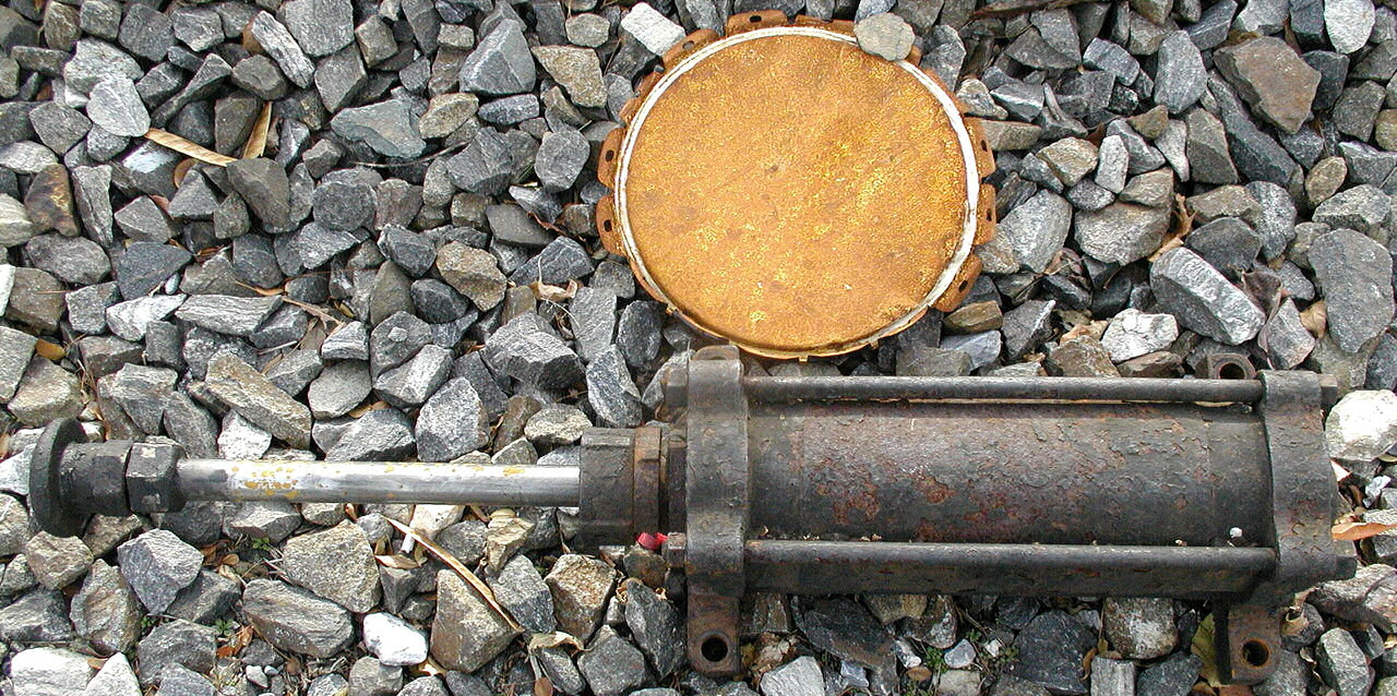
Incidentally a recently discarded pneumatic cylinder was found discarded along the trackbed. Not sure where it came from or why it was just left around, but it illustrates how the things work.
So let's review what we have learned. What happens when you have a slow freight train approaching THORN interlocking and a hot passenger train is coming up behind it? Well without a functional second track or even a passing loop your options are limited, but with some clever thinking here is what you do.
You first switch the freight from track 4 to track 2 westbound.


Then you have the freight train shove backward on track 2 through the interlocking plant.


Then after the passenger train passes...


See, no big deal.
That's enough for the interlocking proper, but I would like to finish with a quick look at the Thorndale phase break and the CTC code line that allows Thorn tower to control its remote interlocking stations.
Here is a shot of the CTC code line before it enters a below ground segment. IP over fiber optics this thing is not, instead consisting of arm-sized bundles of wire pairs some wrapped in a pre-polymer lead sheath. In this are the CTC code line, various track circuit lines, the block phone and any other spares or power lines.

How does one keep moisture out of an 80 year old telephone line? Well you pressurize it with nitrogen gas. Here is a tank of LN2 I found sitting along the right of way. You can tell its being used due to the ice formation from the adiabatic cooling.

The tank of gas is hooked into one f the lead wrapped code lines to pressurize the line and keep out moisture.


I mentioned the Substation that was built as part of the 1939 electrification project. This converts 132Kv 25Hz transmission current to 11Kv 25Hz for the overhead power supply.


Back in the 1930's the electrical grid wasn't synchronized over large regions as it is today so the PRR had to install Phase breaks for when the different power supplied went out of phase. This is no longer a problem, but the breaks remain to separate the electrified lines into isolated regions if necessary. The phase break signals told the engineer he was approaching a dead section of catenary and had to not draw power while passing through it. When the break was inactive the 4-corner position elements would illuminate. When active all 8 would illuminate. Here is the seemingly inactive PB signal on track #4 westbound.


Well that's all I have for today. If you are interested you can review the full set of pictures here
Great to see some of the 1930s PRR engineering work holding its own in the 21st century.
ReplyDeleteI found it helpful to reference the 1992 track charts at http://www.blockstation.net/AMTK-Phila-Div/Section-C/C-7.html while reading this.
On the second video, wasn't the train traveling on #4 westbound?
On the second picture, wouldn't 58L be the remaining active signal for #4 track?