Search This Blog

Tuesday, November 30, 2021

Coal Country Signaling Hit Hard by Declining Traffic

 Early this year the perils facing the extensive rail infrastructure in the eastern coal region were brought to light then NS threatened to remove the signaling from a number of coal dependent lines in its territory.  While many of those applications were withdrawn, according to a recent article, it seems that CSX is also working on downsizing its coal related infrastructure.

Siding removal on the C&O Signaled Coal Creek Sub

This is likely to affect lines that CSX had previously declined to put attitudinal investment into due to the anticipation of a drop in coal traffic.  While this had the positive effect of preserving the C&O signaling and/or the C&O aspect system, at some point the bill will come due and either the signaling or the entire line will be abandoned.

Unfortunately the cutbacks are also affecting lines CSX did spend the money to re-signal, but in these cases taking double track segments, sidings and other pieces of the physical plant out of service.  This specifically applies to the former C&O main line from Richmond to Cincinatti that was re-signaled without much in the way of rationalization between 2010 and 2014.  While the C&O signals were removed, quite a bit of interesting signaling remained with back to back interlockings and other oddball layouts.  The phantom rationalization will reduce signaling locations and possible signal indications, although the low traffic levels will also do a lot to limit what a signal fan might happen to run into.  Amtrak's Cardinal runs along this route and I'd promote taking it if a baggage car wasn't currently strapped to the rear.

Although highly detailed documentation of modern signal locations isn't a good use of time, it is often still worthwhile performing a basic documentation just in case these sort of economic factors come into play.

Sunday, November 21, 2021

PHOTOS: NORTH PHILADELPHIA Tower

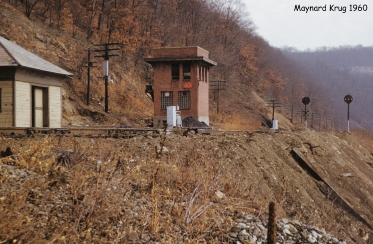
In my previous post, I covered the history of NORTH PHILADELPHIA Interlocking and Tower that were constructed as part of a 1915 improvement project to build a brand new main line passenger station at what had been known as Germantown Junction on the PRR's Connecting Railway. In this follow-up article I will cover the tower itself and its interior as they stood on the eve of closure in 2005 after 90 years of service.


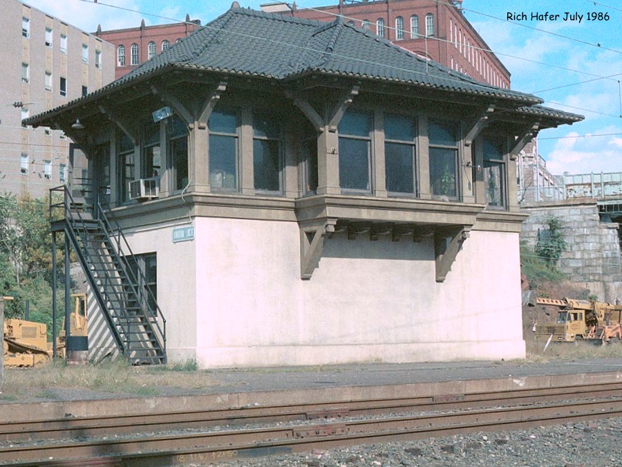
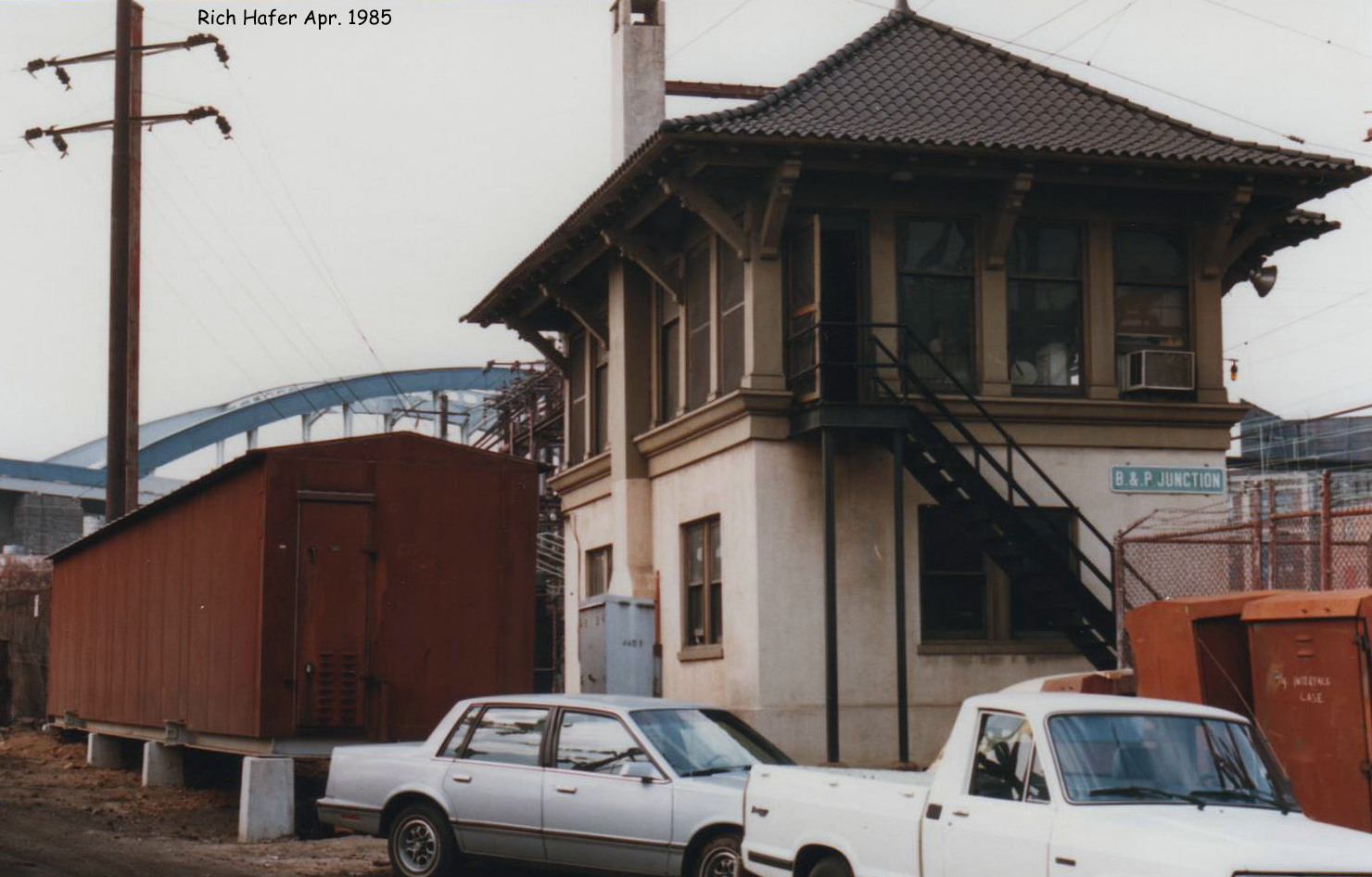
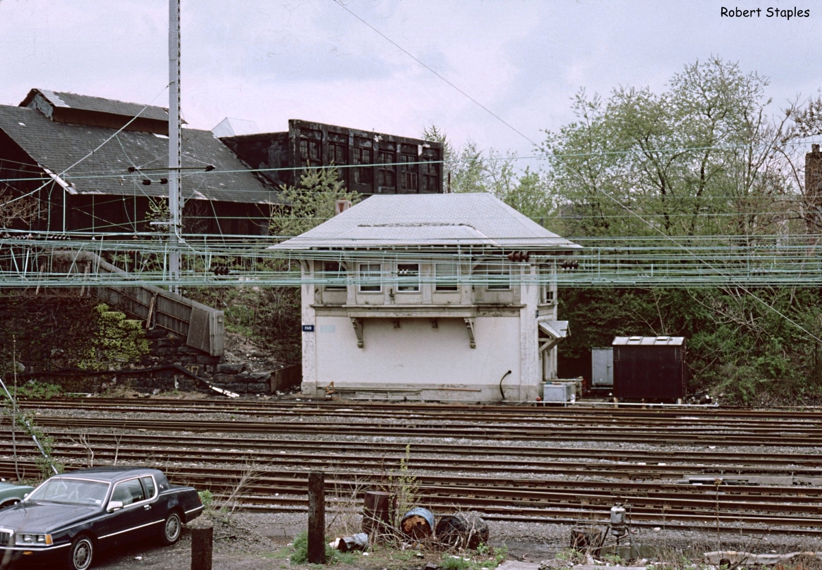
Although the adjacent North Philadelphia station itself is described as being designed in the Châteauesque style, NORTH PHILADELPHIA tower itself is more in line with UNION JCT and B&P JCT towers that were built as part of the Beaux-Arts Baltimore Penn Station project of 1911. From the outside NORTH PHILADELPHIA appeared to be an identical twin of FAIR tower located 30 miles to the north in in Trenton. However despite having been built at the same time, FAIR utilized an electro-mechanical US&S Style P interlocking machine, an example of railroads in this period hedging their bets in regards to purely power operated interlocking plants. Although both FAIR and NORTH PHILADELPHOIA interlockings served stations with high level platforms, station tracks and a double slip ladder, NORTH PHILADELPGIA would stay in service a decade longer, despite FAIR having its Style P machine replaced by a spiffy Model 14 in the 1930's. It would also avoid FAIR's severe case of "tower window syndrome".


As documented in a period article in the journal Railway Signaling, NORTH PHILADELPHIA was state of the art with an all electric Union Switch and Signal Model F interlocking machine, illuminated model board and glass encased route locking cancellation timers.


As I detailed in the previous post, NORTH PHILADELPHIA's interlocking plant would see many changes over the years, including a change from electric to pneumatic switch operation, but despite all this the tower retained its original 47-lever 
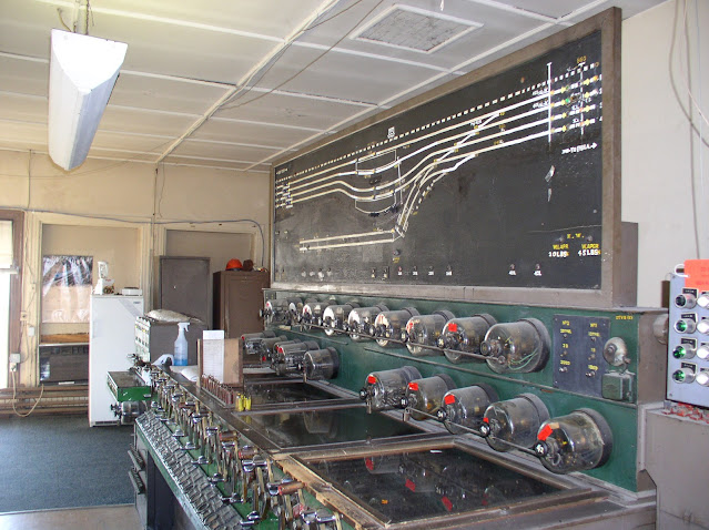
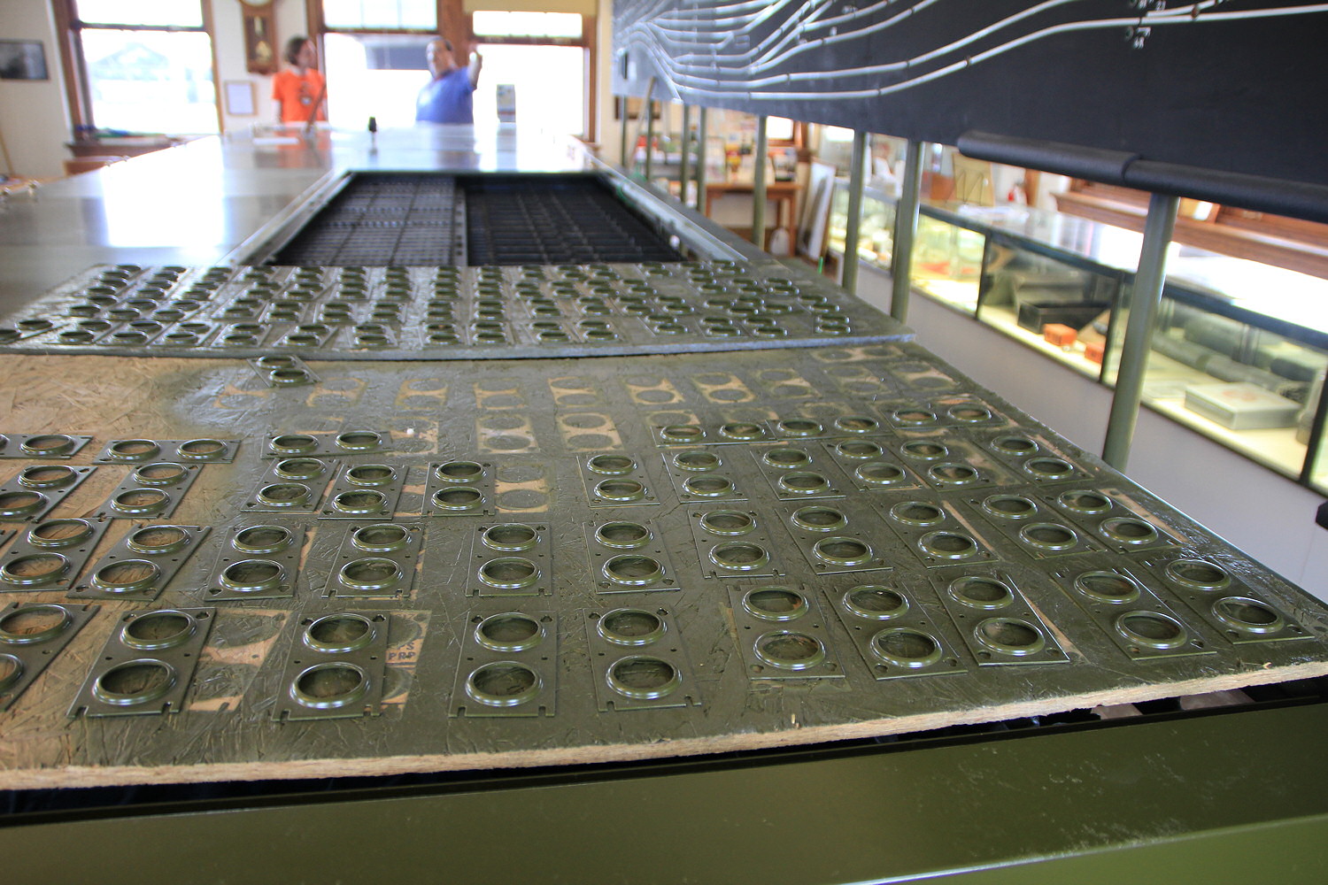
Model F interlocking machine. The photo below has captured the NORTH PHILADELPHIA machine in its 
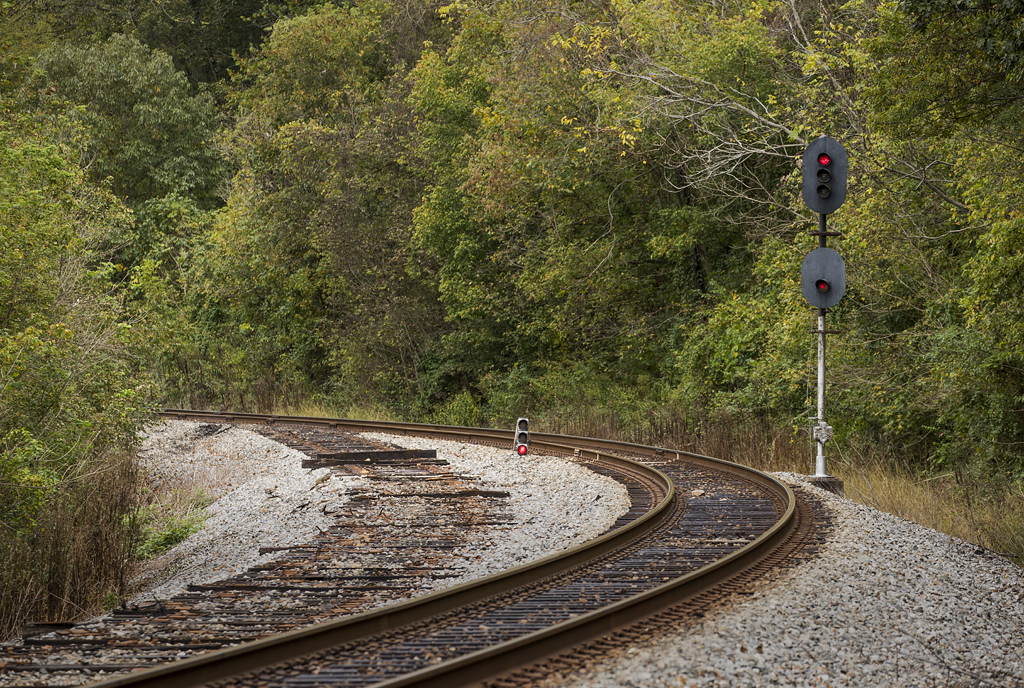
late 90's configuration with former 0 Track at the top separated as the Conrail Trenton Line, but the other freight and station tracks still present.  Also note the east end's trailing point ladder and the Chestnut Hill Branch crossover.  That crossover was a later addition and we can see how it necessitated re-drawing the Chestnut Hill Branch horizontally along the bottom of the model board when comparing with the 1915 photo above.  We can see the Rule 251 between here and SHORE via the 835 and 844 single direction automatic signals.  Makes you wonder if an operator was ever able to arrange a movement from #1 track to #1 track via #5 track through the station. 🤣


Skipping ahead to 2005 we can really see just how much was removed before the tower was closed. Compared with the 90's photo many of the upwards pointing switch levers on the left of the machine are out of service with their numbers missing. Although similar to the more refined Model 14 in operation, NORTH PHILADELPHIA's Model F featured a glass top, to ensure the full employment of signal maintainers, and a row of cast lever indication lamps instead of the later Model 14's use of stamped sheet metal. Other changes from the 1915 depiction include the removal of the electric switch amp meter and additional rundown timers to prevent delays at peak times if routes needed to be changed. In fact the provision of a clockwork rundown timer for practically each signal lever was almost unheard of luxury in the industry, which speaks to the financial resources of the PRR.  In the 2005 photo red tape with updated rundown times have been placed on the timer globes, perhaps indicating that the various signal changes on either side of the legacy plant required the times to be updated.


On the right side of the main machine we see the train announcement bell and higher numbered levers.


On the left side of the main machine we find the lower numbered levers along with the 4-lever table interlocking machine for the Chestnut Hill branch crossover supporting levers 50 through 53. Note the amount of space in this tower on either side of the lever frame which explains how FAIR tower was able to support a 75-lever Model 14 in the same physical space.


On the right side of the model board we can get a somewhat closer view of the changes that took place between 1999 and 2003. The gold stenciled labels on the board are original with the hand painted white and yellow indicating modifications. Removed portions have blacked out with paint, however most of the previous layout along with some labeling can still be seen. All four tracks to the west were bi-directional Rule 261 starting in the PRR era, but dedicated traffic levers were not provided at either NORTH PHILADELPHIA or ZOO. The red lamps at the bottom indicate which signals were currently displayed for train movements (in this case the 28R for one on track #3 west). There is also the west end low air warnings with lamps to 45psi and 20psi and a dragging equipment detector (DED) reset panel for DED's on eastbound tracks #1 and #2.


As of mid-2003 the entire east end of the plant was remoted to CTEC Section 6 as CLEARFIELD interlocking and was literally wiped off the model board despite physically occupying the same space. Because the east end no longer exists, displayed signal lamps have had the labels painted over and track indication lamps have been largely removed except approach lamps on tracks #3 and #4, which likely still give some reasonable degree of warning that a train is heading west from SHORE. Mirroring the west end we see an east end low air alarm as well as DED resets for westbound movements on tracks #3 and #4. Also missing is the 53 trailing crossover on the Chestnut Hill Branch.


The 10, 12, 14 and 16 signal levers previously controlled all main line signals through the east end and were repurposed as traffic levers as the simplest way to integrate the old 1915 mechanical interlocking logic on the west side with the modern interlocking on the east end. Observing the #14 lever lit for a westbound movement on track 3, appears that these levers must be operated for each movement, just like they had as signals, otherwise no direction of traffic is set.

Sunday, November 14, 2021

US&S CTC With Coded Track Circuits

 For years I have been aware of a major split in how Traffic Control systems function at a technical level. In the US&S corner is the "traffic lever" system where segments of track have a set current of traffic set by a figurative traffic control lever. In the General Railway Signal corner is a different system where intermediate signals can float in both directions once a train has passed and if no following movements are routed. In an effort to get to the bottom of how these two systems worked I purchased the GSR Elements of Railway Signaling book, but as I mentioned in my review the book somehow failed to provide any real insight.


Fortunately, while searching for information on the PRR's BRADY tower on the Allegheny Valley Branch near Brady, PA, I stumbled upon a Railway Signaling Journal article on the 1944 BRADY CTC project and its use of coded track circuits, which are the same kind used in PRR/US&S cab signaling. This article not only explained why the US&S system worked the way it did, but also a number of other observations I had made over the years, such as intermediate signal locations suddenly springing to life when a route was established.


The key insight to this system is that when a track segment between two interlocking is idle, a steady flow of current is transmitted in the direction of traffic, similar to a 2600hz idle tone in old long distance trunks. Intermediate signal locations pass along this steady current until it reaches the next interlocking location that the logic interprets as the track segment being unoccupied. A request to route a train terminates the steady current at the near end and when the far end sees the energy turn off, it begins to transmit the 75, 120 or 180 pulse per minute track circuit codes we all known and love towards the near interlocking. These codes then propagate through the intermediate locations, setting the directional relays and illuminating the signal lamps and activating code generators to pass the block state on to the next signal location. When the near interlocking sees these track circuit codes it is able to display an appropriate signal.


If no following movements are planned, the near interlocking will once again transmit steady current into the track segment in the direction of traffic set by the CTC system. Intermediate signals will continue to transmit block state codes in accordance to their directional relay until they detect the steady current, at which point the directional relay is reset and the active elements of the intermediate location (signal lamps and code generators) will be turned off. Changing flow of traffic via a literal or figurative traffic lever will determine which interlocking at either end of the track segment is transmitting the steady current idle signal. This system is extra clever because in addition to not needing to transmit block state via a pole line, it is also fail-safe as any disruption in any track circuit in the track segment will register the occupancy on the CTC console.


These details explain a number of observed behaviors such as the aforementioned signal location on the US&S signaled Bessemer and Lake Erie springing to life suddenly when a route was established or the intermediates on the Port Road having the reverse direction dark.  Either way it also explains why traffic control on these systems are so liable to "get stuck" and why such a situation can be a headache to resolve. Even in CTC systems where the observed behavior is different, such as continuously operating signal lamps and/or cab signal code, steady current messaging can still provide a simple mechanism to flip intermediate directional relays and establish directionality.

I urge everyone to read the primary source on this topic.  It might take a few reads to get the finer points, but its leaps and bounds more approachable than the Elements of Signaling book.


Saturday, November 6, 2021

What Infrastructure Spending Means

 The new trillion dollar infrastructure package will likely have an impact on that I will call "interesting signaling", I suspect mostly by replacing it, but in a few cases adding in stuff that wasn't there before. We've been through this before with the 2008 infrastructure package trickling down to various rail projects such as the New Jersey NEC modernization that brought in Rule 562 signaling between HAM and COUNTY.


Take the New York Penn Gateway project.  The connections to the new tunnel could be built as part of the existing pneumatic point machine plant, it could be built seperate from it, but leave the existing plant alone...or it could result in the whole Penn Station getting electric M3's.  

For good or for ill the PTC push has pretty much decimated signaling across the board.  What am I most worried about with the new infrastructure money?  Well a complete NEC rebuild would eliminate the remaining pneumatic plants and  intermediate PL signals.  NJT, METRA, SEPTA and the LIRR also have a number of more vintage signaling elements that have hung around due to a lack of funding. The good news is that it feels that bigger ticket items will be the target of this money as signal modernization might have a limited ability to surge (or not as the PTC push is over) and is not as critical. 

The position examples include things like the Glassboro, NJ line or other light rail projects that would use somewhat oddball signaling like IIATS or Westcab train stops.  There are also plans to restore passenger service to places like Allentown or Scranton that might see not only an expansion of Rule 562 cab signaled CTC, but also target type signals, especially in the northeast. All in all its a mixed bag and only time will tell.