Search This Blog

Showing posts with label relay. Show all posts

Saturday, May 10, 2025

The Enthusiasts Step Up

Unlike Europe, Heritage railroads in the United States never developed a vintage signaling component beyond what one might describe as display items. The big reason for this is that in service signaling and interlocking appliances have significant regulatory inspection, testing and documentation requirements that are beyond the reach of most tourist train operators. The result has been that most preserved towers are completely inert, with just a handful having interactive elements such as operable interlocking machines (SS43 BERK) or full on simulations (HARRIS). However, in recent years it seems that the private collector/enthusiast space has been stepping up to fill the gap as exemplified by the small YouTube channel Laser 711.

Signal and signaling equipment collectors have been around for some time, snapping up such items as model boards, CTC cabinets, full size signals and even interlocking machines. Until recently, railroad signaling departments would tend to keep their retired equipment, as similar vintage hardware was still broadly in service and the parts to maintain them were no longer being manufactured. However, the PTC related re-signaling push rapidly phased out so much of the relay era railroad signaling that the equipment is now being sold for scrap or offered free to anyone with the capacity to haul it away. 

In the context of interlocking towers, model boards and CTC cabinets have been widely collected for some time as switch to video display in a dispatch office had long ago destroyed their reuse value. Somewhat ironically, it was the older mechanical and electro-mechanical interlocking machines that retained the most value as a source of spares for their kin.  (For example a major reason LENOX tower near St. Louis was closed was to supply parts to the CNW LAKE ST machine in Chicago.) However as the number of these in service interlocking machines hit zero, anyone with a large enough truck could cart the survivors away for their own personal amusement. This is where Laser 711 comes in, having apparently set up not just a HARRIS style PLC backed simulation, but the full hardware stack including relays, point machines and signals.

 He has also restored an ex-Erie CTC console from BK tower along with its original code system, and now appears to be in the process of implementing as much field functionality as possible "in relay".

Of course it would be great if more publically accessible museums were able to step up to the plate with functional period correct signaling equipment, but the signal enthusiast community, powered by recent advances in the "maker" scene and high capacity pickup trucks, seem to be taking up a lot of the slack. Just like we have seen with the extensive telecom switch collection of Step by Step Phil, these private efforts stand a good chance of eventually finding their way into durable preservation.

Attempted CTC at the Seashore Trolley Museum

I will also mention that non-FRA regulated streetcar/transit museums have the best capacity to implement "live" historic signaling. When visiting Shoreline Trolley Museum I was shown their "in-progress" CTC system that they were building from thousands of relays donated by Amtrak and Metro North.


The fact that I have not heard much if anything about that project in the past 20 years hints at its priority in the greater scheme of things, but all it takes is the right team of enthusiasts to get a project off the ground.

Tuesday, May 31, 2022

GRESHAM JCT's Sequence Switches Explained

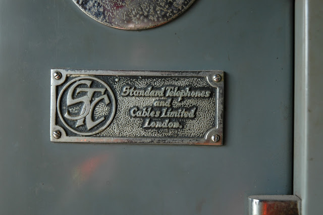
 Years ago I wrote up a profile of METRA's GRESHAM JUNCTION tower on the Rock Island division south of Chicago.  Not only had GRESHAM JUNCTION managed to stay open into the 21st Century, it was a unique North American example of a sequence switch interlocking. Supplied by the Standard Telephone and Cables Company of London, the interlocking used telecom grade sequence switches to carry out the interlocking functions instead of relays.


In my original post I provide photos of the equipment as well as a general concept of how sequence switches work and some sequence switch interlocking circuit diagrams from the UK, but without time and access to the equipment or someone who was intimately knowledgeable about how it functions, my commentary had to remain at a very high level.  Fortunately, the gang from the Connections Museum in Seattle is on the case because sequence switches is pretty much how Bell Number 1 Panel central office machines functioned (again, as opposed to later relay based technologies). I could try to go into things, but fortunately the museum's YouTube channel has video that is specifically about how sequence switches work. 

Once you see them in action at the Connections Museum, their function in the photos from GRESHAM JCT will become obvious. Of particular note is the function of the magnetic clutch mechanism that rotates the switch spindle. Perhaps if I stare at things enough I can determine what each sequence switch corresponds to in the interlocking.  Is each a complete route? An entrance? An exit? An entrance-exit combination? Let me know in the comments if you figure it out.  BTW, if you like this video take some time to watch the rest of the Museum's content.  It's top notch and does a superb job of explaining some normally opaque topics in the realm of pre-modern telephone switching technology.


Saturday, February 12, 2022

Interlockings vs Cyberattacks

 With the use of cyber attacks and physical sabotage increasingly likely, I thought I should take the time to discuss the vulnerability space of good old fashioned railroad interlockings.  I say old fashioned because at this time I do not want to re-hash the security issues associated with CBTC and PTC.  Today I am just going to look at the logic that controls the switches, signals and related interlocking appliances and ways they could be directed to disrupt normal operations, specifically through the creation of unsafe situations.

Railway signaling is implemented by two separate yet equally important parts.  The safety critical logic that detects and prevents unsafe situations, and the control systems that display information to rail controllers and transmit that information to/from field locations. In the same vein, one can attack the interlocking logic or one can attack the control systems and in each of those cases one can try to make the system non-functional or one can try to make the system unsafe.  So before even getting into the various types of technology we can sort the threats and vulnerabilities into those four bins.

Skipping over mechanical or electro-mechanical plants where the interlocking logic and the user interface are united and a human is on site to monitor things, relay based signaling is going to be the most resistant to malicious change.  Relay logic is literally hard wired and extensively tested for safety meaning that there is little an attacker could do, even if they had full control over the communications link and human interface. In terms of physical attacks and sabotage operations on the other hand, relay logic can be modified with only basic tools.  Although the mess of wires in a relay hut or room is very complicated, the concepts are straightforward and can be determined using the documentation that is often left in each location.  North American style logic is a bit simpler to modify as it relies in high reliability components whereas European style logic uses lower quality components with additional validation logic to check the result.

Solid state or microprocessor based interlocking became all the rage starting in the 1980's and continues to command an increasing share of the market.  This type of technology unfortunately imports all of the problems associated with industrial control systems and Internet of Things from a security point of view.  The good news is that these components undergo rigorous safety and regulatory compliance testing, the downside is that tends not to include security testing.  Unfortunately I can't just say "this is good because" or "this is bad because" as there are simply multiple ways that any specific vendor may have implemented its technology.  Still, there are some general conclusions that can be reached.


Microprocessors run on code and code modification and/or code injection forms the basis for most types of malicious exploitation.  Under North American practice, the code is stored on Read Only Memory type modules (likely EEPROMs) and is a regulated item in that no official changes can be made without going through a regulated test procedure. The $64,000 question is if, if any case, the processor accepts data, or if it accepts state.  Accepting state means that to request a route the only thing the interlocking logic "sees" is a voltage on a line in the same way a direct wire unit lever relay interlocking machine puts a voltage on a coil to lift a relay.  Accepting state only generally precludes modifying the code.  On the other hand if the interlocking processor accepts bytes of data, it is almost certain that flaws exist within the code that would allow an attacker to take full control of the interlocking process given sufficient knowledge and preparation. The fact that many of these  product lines have been around since the 80's or 90's imply that they use older types of processor that have little in the way of hardware based defenses against this type of attack.

Larger issues appear outside of North American practice where interlocking functions are more centralized and therefore have less obvious separation between the safety critical parts and the control system.  Under North American practice interlockings and signal locations in general have to be transferable to new owners.  This means that not only does each location need to be atomic, but forwards and backwards compatible with any control system.  (That pretty much makes it impossible for the signaling hardware to require data.)  Under European practice, centralized interlocking/signaling systems lack the guardrails against plugging the human interface directly into the safety critical processing elements.  I believe that 2 of 3 voting systems are used to gain the desired fail safety performance, but since Europe often considers the human interface as a safety critical system, I would not be surprised if the signaling processors themselves are handling state requests and changes directly. This creates a massive vulnerability for exploitation.

This brings us to the control systems.  Here we need to look at both what is being sent and how its being sent.  If one is only sending state or state commands, as in the North American system, the signaling control network is pretty much irreverent.  Over the air or over the internet there is nothing an advisory can do except make the system unavailable (which is a problem, just not a safety problem).  Even if state updates are suppressed, North American dispatchers worked successfully for years in that fashion given the limitations of early wide area CTC systems. European style area signaling schemes run into a different set of problems when signaling logic is centralized.  In this case field equipment such as switches and signals act as dumb terminals and simply do whatever they are commanded to do.  This is where the serious risk lies as it is highly unlikely that a 1980's or 90's grade computing system would have much in the way of "securing" its safety critical messages beyond a parity or other redundancy check. Anyone with access to the communication link would be able to make arbitrary commands including the setting of conflicting routes and display of false clear signals.  Granted many of these area schemes are not wide area and use dedicated lines that can be considered equivalent to some of the longer direct wire control situations in North America, but in an era of IT efficiencies how tempting would it be to replace a bespoke wayside cable link with a VPN running over the internet.

In terms of direct sabotage, card based microprocessor systems are somewhat harder to modify than relay ones as they require special reprogramming tools ranging from EEPROM programmers, link cables and the almost certainly proprietary software used by the C&M maintainers.  It's entirely possible that the available tools would themselves would not allow for the creation of unsafe situations, thus requiring further reverse engineering.  Nevertheless, cyber-physical systems still have a physical component and it is still possible to move output wires around to create the desired result.   

I hope this provides a little insight into how train control and interlocking systems can be attacked by either remote or local actors.  In the grand scheme of things, physical sabotage is generally considered to be beyond the scope of technical security beyond the presence of robust locks and an alarm system. However, during some sort of armed conflict or occupation the possibility of such attacks would increase.


Saturday, March 20, 2021

PHOTOS: Bonus Port Road Trips - Inside COLA Tower

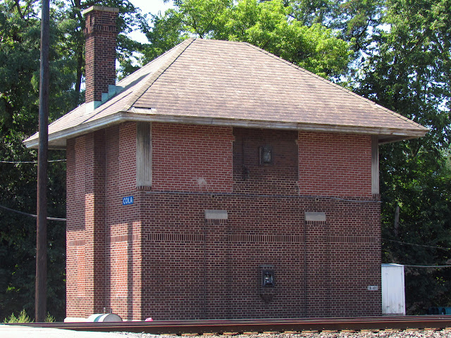
Opened in 1938, COLA tower, in Columbia, PA was closed around 1986 and then served as a glorified relay hut until 2012 when the interlocking it controlled was re-signaled. In the decade that followed, the tower, sealed up against the elements and scrap enthusiasts, has been left largely untouched. Possibly still used as an employee clubhouse or storage facility, the stout construction and generally benign location have managed to defend the structure from demolition. I recently came into possession of some interior photos, taken a some years ago, that shine a light onto the tower's life and post-life.


Built at the same time, with the same design and for the same electrification project as the previously covered THORN tower, COLA used CTC remote control technology (although not much actual CTC territory) to streamline operations at what would be the hub of the low grade freight network between the Main Line junctions at Parkesburg and Perryville, and the massive Enola Yard near Harrisburg. COLA interlocking and its extended CTC territory were all extensively covered in my Port Road Trips series and so I will try to avoid covering the same ground again, however the key point worth remembering is that COLA's status as an all-relay based interlocking plant meant that when Conrail's NEC operations were severely curtailed in the mid to late 1980's and the east-west portion of the low grade network was abandoned, Conrail was able to close the tower as a Block and Interlocking Station, brick up the windows, install an interface and control the whole plant from a computer terminal in Mt. Holly, NJ just as easily as it had from the operator's console on the second floor. 


25 years later Norfolk Southern finally got around to replacing the still 1938 vintage signaling at COLA as part of an area re-signaling scheme that covered much of COLA's former CTC territory and it turns out that they pretty much locked the door and walked away. On the operator's level, the CTC console has vanished (most likely into an employee's basement), but it's outline is still present along with the operator's chairs and a pretty snazzy Kelvinator.


Lockers for the operators are still standing against the wall and one can see the crudeness of the 1980's brick job compared with the large tile on the proper walls. At least Conrail decided to opt for brick as opposed to cinder blocks or plywood. Also note the institutional grade water fountain, which were the style in the days before bottled water.


On the wall behind the operator's position are a variety of railroad preservation related news clippings, pasted up an "enthusiast" operator along with various notes of a more work related nature. Banana stickers abound along with clues that smoking as still permitted inside.


The washroom appears to be of PRR vintage and along with the radiant heat system speak to how the ostensibly value focused PRR wasn't afraid to pay for quality. COLA, with its CTC system and indoor heat and plumbing was state of the art in 1937, on par with today's amenity filled Silicon Valley HQ's.

Saturday, June 16, 2018

Railroad Signals and the Materials of Yesteryear

NOTE:  This article first appeared in the Summer 2017 issue of The Trackside Photographer.

In 1967 young people were told that plastics were the future and the future did not disappoint.  Today the world is made out of plastic, carbon fibre, corrosion resistant lightweight alloys, high strength concrete and LEDs.  This technology has generally converted our world from one where stuff is expensive and people are cheap, to exactly the opposite.  I could go on and on about the many economic ramifications of this, but in essence "things" went from being crafted and artisan, to being so invisible that they might as well not matter.  Back in the day the Pennsylvania Railroad was the largest private employer in North America with over 300,000 employees, roughly the same as WalMart.  This vast army of workers was needed to polish, paint, lubricate and generally maintain all of the expensive, labor intensive technology that allowed humans to move at speeds faster than brisk walk.  Replacing the materials of old was part and parcel to being able to replace the workers that cared for them, however as we charge into the middle of the 21st century some of these materials have soldiered on in the service of railroad signaling and, until their inevitable replacement, they provide a window into the pre-digital industrial age.

CSX Washington Sub - South Orange Interlocking
Steel and iron are the stereotypical railroad materials as demand for bridges, rails and locomotives practically created the modern steel industry.  Of course steel wasn't just used for girders and boilers. Back in the day this was the only metal one had available for structural components of any size and before the advent of plastic or other composites, metal was one of the only materials available with an adequate strength to weight ratio.  Stronger, weather proof and more durable than wood, iron and steel became the materials of choice ofr railroad signals and signal structures.  This US&S style N color light signal mast shown above is almost completely made of iron and steel, right down to the base.  Cast iron housing and brackets, sheet steel backing, steel pipe mast, strap iron ladder work, heck, even the signal wires are sheathed in iron.

CSX Philly Sub - MP 80 Auto Signal "Whitemarsh"
Cheap and easy to stamp, cut, forge or cast, steel was everywhere, but it's suffers from a major weakness against air and water.  The scourge of rust requires care and paint, and paint requires workers to apply and remove.  In the 21st century aluminum is cheap and plentiful.  Lightweight and rust free, any signal made of aluminum will look as good on the day it is installed as the day it is removed perhaps decades in the future without needing so much as a man hour of skilled labour.

CSX Cumberland Sub - Paterson Creek interlocking

Also used for bridges and track structure, wood was the plastic of its day.  Light and easy to shape, it also has tensile strength allowing it to span distances in a way that stone or concrete cannot.  Although it was excluded from most signal structures, wood was employed in pole lines to support the signaling and telegraph wires that carried little bits of voltage from one signal location to the next.  Unlike steel, stuff can be easily attached to wood with nails or screws and, somewhat surprisingly, wooden poles can also last decades after being impregnated with petrochemical tars.  However modern technology found other ways to eliminate the wooden pole lines by replacing the wires they carried with fiber optics or wireless signals.

D&H 'QS" Interlocking, Mechanicville, NY
Surprisingly, cotton was an important material in railroad signaling.  Before the advent of PVC sheath insulation, large signal cables were wrapped in cotton impregnated with tar to keep out the elements.  Cotton insulated cables went hand in hand with the pole line concept as attempting to bury such a cable would quickly lead to its failure.  Damage vulnerable to wind, snow, rain and trees, this was accepted a cost of doing business.

PRR 138kv Transmission Line near Martic Forge, PA
From the smallest telegraph wire to the thickest high voltage transmission cable, copper carried the electrons that powered the signals and sent the data.  Synonymous with the term "electrical conductor" to this day, copper was generally replaced by aluminum braids in power applications and of course its role in data transmission was tied to the pole line . Ultimately railroads did all they could to get out of the power transmission business, in some cases going as far to replace copper cable with solid state solar panels.

CP-MIDWAY - Port Road Branch
Large ceramic insulators met the same fate as the copper wire when the business of providing signal power was turned over to the local utilities.  Outsourcing is the name of the game in the 21st century.  It made no sense for railroads to act as power companies, employing linemen and stocking electrical hardware such as this.

CP-SLOPE, Altoona, PA.
PCB's are probably the best class of material for insulating transformers being non-flammable and possessing a high dielectric coefficient.  Unfortunately they also cause cancer and persist in the environment almost indefinitely.  All the more motivation for railroads to stop running their own power grids.

CSX Cumberland Sub - Magnolia, WV
 Glass was the insulator of choice for low voltage signal and telegraph wires running along side the power supply lines on the poles.  Edging out ceramic in the same use case, the sparking glass insulators made railroad poles a look a bit like Christmas trees.  Replaced at first by cheap rubber and plastic models and ultimately by wireless, glass insulators became a staple of country antique shoppes and the preferred target of rural target shooters.


More expensive than its pole line cousin, optical glass collected the light from the low wattage signal bulbs and and protected it 1-2 miles down the track for approaching trains to see.  Most color light signal lenses consisted of an inner colored glass filter assembly with an outer Fresnel lens that focused the beam.  Today these have been replaced by high intensity LED's that often do not need a focusing lens, making do with a cheap clear plastic cover.

CP-RADE, Radebaugh, PA
Compressed air was the power source of choice for many early power interlocking installations.  Not only were air operated switch machines simple and cheap, it was also easy to safety control the flow of air using low voltage electrical circuits passing through an electro-machanical interlocking machine.  Of course air was only cheap as long as the workers needed to keep the lines dry and leak free were also cheap.  Today pneumatic switch machines are fading fast in the presence of bullet proof, high voltage electric machines.

CP-TRAFF, Trafford, PA
Silver paint is typically applied to relay huts and cabinets to reflect the sun and keep internal temperatures low.  In this case the need for painting has been replaced by corrosion free shiny materials and compact air conditioners.

CP-HAWSTONE, Lewistown, PA
Lead acid batteries were once provided in large quantities for when the railroad supplied power suffered some sort of outage, as was frequently the case in the pole line era.  Because the batteries would vent hydrogen gas as they charged and discharged, they were stored in concrete "wells", outside the relay huts where there was no risk of explosion.  Today improvements in battery technology and power reliability have made such large bulky backup power arrangements unnecessary.

PRR OVERBROOK tower.
Relays are constructs of copper coils moving silver plated electrical contacts to make and break electrical circuits, all sealed up in a glass envelope.  Once the standard unit of electronic logic until the advent of the transistor, the function of relays was duplicated by solid state gizmos such as transistors.  Relay logic was standardized across vendors and can't be hacked, but changes are costly and time consuming to implement, making software based alternatives far more attractive.

CSX Cumberland Sub MP 130 Auto Signal "Drywall"
Up through the middle of the 20th century railroads were once at the vanguard of technical innovation, leading the way in telecommunications, computing and material science.  While today these technologies and materials of yesteryear can make railroads seem like an under-funded anachronism, a different view shows how well the engineering of the past has stood the test of time.  While the materials of today are in many ways superior, they lack much of the spirit of what came before.  A spirit created by human hands crafting, fitting and maintaining the materials of yesteryear from one century to the next.

Sunday, June 3, 2018

Caught on Camera: Bobbing SEPTA Main Line Signals

Several years ago I discussed the topic of relay logic and how it can create interesting signal displays as they change from one aspect to the next.  (Usually this involves a change from some form of Clear to some form of Restricted Proceed as that involves two or more discrete relay flips.)  Well last week I had taken a trip to the SEPTA North Broad station, just south of the busy 16TH ST JCT, to photograph the last remaining AEM-7 locomotives in operation.  At one point, towards the tail end of the peak period, the track 1 signal on the Milepost 2.9 automatic signal bridge began to cycle between Approach Medium, Approach and Stop and Proceed.  The northbound home signal at 16TH ST was displaying Medium Clear, so Approach Medium was indeed the correct indication, however the signal continued to move between the three at a fairly brisk clip indicating that the track circuit between there and the interlocking was moving between an occupied and an unoccupied state, a phenomena known as "bobbing".


As time went on the rate of the cycling increased and as soon as the AEM-7 led push-pull on the adjacent track 2 cleared tthe approach block to 16TH ST, that signal began to bob as well, although only between Approach and Stop and Proceed. In due time a northbound train approached the 29-1 signal and I can only imagine what the crew was thinking as they not only watched the wayside signal change ahead of them, but also endured a constant stream of cab signal flips. As one might have expected, the train passed the malfunctioning signal at Restricted speed and shortly thereafter the track 2 signal was also brought down to the Stop and Proceed position full time by an adjacent northbound train.


After the two trains passed whatever temporary fault condition that existed was resolved and the MP 2.9 automatic signals went back to normal operation.  There was a later service disruption at the junction, but it appeared to be related to some sort of stuck switch or disabled train. The funny thing was that this wasn't even my only recent encounter with bobbing signals as I also caught two northbound signals at Milepost 69.6 on the Amtrak's Southern NEC also bobbing.


Some bobbing track circuits can be fixed with a few simple adjustments.  Others can be quite stubborn and can linger for weeks.  Some parts of the southern NEC had bobbing circuit conditions that had been around for years, often where electric movements on one trackcould cause an adjacent track to temporarily show occupied.


Wednesday, February 28, 2018

Northern Buffalo Line Trip Report

So after reporting that the PRR signaling on the Northern NS/Conrail/PRR Buffalo Line was in danger, I took a trip up to the Williamsport, PA area to take what photos I could before everything went away.  Previously NS had re-signaled everything from the north end of Northunberland Yard through to the wye complex at Linden.  I had visited the latter location back in 2006 when I was chasing a Levin sponsored PRR E8 trip to Renovo and knew that classic signals were still in place through to Lock Haven, however replacements were in the process of going up.  Long story short if you'd like some spoilers, my buddy Todd has already posted his trip report, but I have a few takeaways of my own.


First of all NS did carry out a general signal refurbishment project so the old PL's will be looking their best when they are unceremoniously ripped out in the next few months. although that did mean the demise of the pneumatic point machines.  Second, CP-RIVER, which used to span the entire length of the Susquehanna River Bridge at Linden, has its northbound signal moved to the south bank, probably so the LV RR shortline could take full responsibility for the bridge.


After the Linden complex I tried to stop by CP-BUD, but found it to be inaccessible thanks to a gate closing off what is nominally a private road serving some vacation cabins, however I was able to document CP-PINE and the two famous 2-track PRR signal bridges between CP-PINE and CP-LANE.  Moreover, just south of the MP 197 bridge there is also an abandoned weigh-in-motion scale that has the equipment arranged in a very strange setup on a platform over a river and protected by steel plate armour. 


Getting onto the bad news, CP-LANE, a crossover on the double track just before Lock Haven, PA, had been re-signaled in the same sweep that also hit CP-LOCK HAVEN.  Of course the most shocking discovery was this little sign next to the new southbound at CP-LOCK HAVEN.


Yup, NS has completely scrapped the signaling north of Lock Haven, PA.  They had already cut back the Rule 261 to Emporium, but for whatever reason they just decided to throw in the towel.  You might notice that the northbound cantilever has signals that all support 261 territory north of Lock Haven, but between the time those signals were ordered and today it appears that their plans :-(


All of the relay cabinets have been unceremoniously dumped in the backlot of the NS Lock Haven station/crew base so if you're a relay collector...

Sunday, October 2, 2016

PHOTOS: OVERBROOK Tower - Part 1

So a while a go I posted a piece on Amtrak's OVERBROOK interlocking in the Overbrook neighborhood of Philadelphia.  Today I will be focusing on the interior and exterior of tower itself so if you missed the first port go back and read it over as I won't be reiterating any of the interlocking specific information.  Most of the interior photos were taken in 2003 and 2004, while some of the exterior photos were taken between 2011 and 2015.  Part 1 of this two part look at OVERBROOK will cover the tower's exterior, first floor and Model 14 machine on the second floor.

OVERBROOK tower was built by the PRR in 1926 and was, chronologically, in the first wave of the all-brick style of towers that would become a trademark of the PRR in its later years.  OVERBROOK was soon expanded in 1941 as part of a CTC project that gave the tower control over the remote interlockings VALLEY and JEFF (on the Schuylkill Valley Branch ), as well as having its own limits expanded with control over the west end of Belmont Yard installed as OVERBROOK's "Woodbine" section under direct wire control.


Still, compared to other PRR towers, OVERBROOK is notable for its rather diminutive size.  Similar to later 1930's towers such as WINSLOW and YORK, it still presents itself as a bit smaller, especially compared to its sister towers elsewhere on the electrified main line.


The smaller size is more apparent in the quarter view where we can see that there is only one window on each of the sides, compared with two on the WINSLOW/YORK series of towers.  One feature that reduced the footprint was the location of the air compressor plant outside the tower.


Despite its location in a big city, Amtrak was never hesitant to store spare signaling components such as PL signal targets and A-5 point machine covers, in the open, behind the tower.


Like most PRR towers, OVERBROOK is fitted with an internal staircase with a ground level entry.  The money really shows with Flemish bond brickwork with a number of decorative courses.  Also note the canopy over the door complete with slate shingles.


The PRR standard bay window takes up most of the width of the tower and today is outfitted with a number of VHF radio antennas.  Also present is the interlocking horn, which is still functional and used to clear off people crossing the tracks in the station area.


A train order lamp, consisting of a single PL-2 unit, is still mounted on the east side of the tower.  With 4 tracks and one bi-directional, there was less need for train order hooping at OVERBROOK, but it still took place from time to time.  The 80's or 90's vintage Amtrak tower sign is clearly showing its years.  Don't look for any further investment in tower aesthetics as efforts to re-signal the line loom.


Here is another view of the front of the tower, complete with a 9/11 flag, before the platform was rebuilt in 2003.


Opening the door we are immediately greeted by the sound of clockwork ticking and the smell of the 1940's as we walk right into OVERBROOK's relay room.  Normally the relay room is locked and only accessible by C&S personel, however OVERBROOK is the rare exception where the operator can also poke about in the guts of the interlocking.  In this particular bay of the relay room we can see older shelf relays off to the left and "newer" plug type relays on the right.  Note the maintainer's chair, phone and stash of spare plug relays.  This interlocking and tower is actually assigned its own full time maintainer, likely near retirement and the only person who knows how things works.


The shelf relays are attached to the 1926 portion of the interlocking, which basically means the 4-track crossover.  Unfortunately I took these pictures back in 2003 when my camera card capacity was 96 photos, or I would have taken a lot more.


Wednesday, May 14, 2014

Fire! Fire! Help Me! SS28, New Haven Line

Usually when fire comes up in the context of railroad signaling it;s usually some old wooden interlocking tower or relay plant making use of lots of cotton wrapped wires, but more often than one would think modern metal relay huts catch fire and cause all sorts of headaches for the railroad that owns it.  Well a few days ago a fire broke out in one of the instrument houses serving a complete 4-track crossover on the Metro-North New Haven Line (it's really not their year is it).  The interlocking in question is technically known as CP-219, but the proper designation is SS28 GREEN and for those of your who don't know your New Haven Line interlocking here is a photo of what control the interlocking up into the 1980's.


Fortunately the tower was spared as all the relay logic was moved across the RoW to a series of huts connected by cableways.  Now in some of its interlockings MNRR has installed Halon fire suppression, but Connecticut has not opted to pay for such features, however the extreme cheapness did have some benefits as the use of multiple, small relay huts kept the fire contained to a section of non-vital relays used for CTC code line communications.  Now the only reason I am talking about this is because Metro-North was nice enough to post up a whole set of photos on Flickr in the interest of transparency.


As you can see these aren't the familiar glass cased vital relays that would be both costly and time consuming to replace.  Instead these are non-vital elevator/telephone type relays used in the CTC control elements.  Without any damage to the real interlocking local control can be used if necessary and from the service advisory delays of only 5-10 minutes were encountered at the time of the incident.


Not sure if MNRR is going to try to restore the same functionality or just use some infinitely more simple form of modern technology.  The latter would seem obvious, but since it would probably require a brand new custom interface between the non-vital and vital elements I suspect they'll just bring it back exactly as it was.  Note the worker with the old wet dry vac already putting a "restore" plan back into place.

MNRR didn't stop at photos, they also produced a video outlining their little whoopsie.


Anyway, fires happen all the time, but few are so well documented in a way that can shine a light on the inner workings of modern(ish) interlockings. Which reminds me...if you travel the New Haven line late at night instead of looking to the south side of the tracks where the fire was, look to the north because inside the tower a single bulb still burns illuminating the original interlocking machine which fortunately did not burst into flame during its 60 years of operation.