Search This Blog

Showing posts with label history. Show all posts

Friday, April 21, 2023

Remembering South Jersey's Insulator Ranch

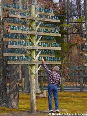
For years, if one were driving near Atlantic City, New Jersey, perhaps taking a shortcut between the Atlantic City Expressway exit 12 and the Garden State Parkway exit 41 due to summertime congestion, one might pass something on the side of the road that might cause a momentary feeling of disbelief where one might question what they just saw.  Located at the edge of the famous New Jersey Pine Barrens in Galloway Township, the slightly less famous Insulator Ranch was chronicled in all the typical quirky attraction websites like Weird NJ and Roadside America as it sat there provoking thousands of double takes over the years. Insulator Ranch was exactly that, a ranch house with a circumferential fence-line  constructed entirely of railroad pole-line poles fully stocked with green glass insulators. 

I first stumbled upon the site in the summer of 1998 and likely passed it once or twice in the years that followed.  In the age of Google Maps I would check in periodically, confirming that it was both still there and that my mind had not been playing tricks on me in ages past. Then, just recently, a check of the updated Street View showed that while the home and property were still there, all the magic of the green glass insulators had gone. According to the reports, the creator of the insulator art piece, a one Stanley E. Hammell, had passed away at age 89 in 2012 and was followed by his wife in 2018. I am sure one could probably dig deep enough to find out what the family did with the over 10,000 green glass insulators, but surprisingly, their fate has eluded the reach of Google. 


Mr. Hammell said that he began his collection in 1985 and continued through to the early 1990's. He talks about train shows and walking various rail lines, all things I am sure he did, but none of the articles provide insight into where I am confident he obtained the bulk of his collection because its the same place that my family came away with bushel baskets of our own. The former Camden and Atlantic, aka PRSL Main Line from Lindenwold to Atlantic City.

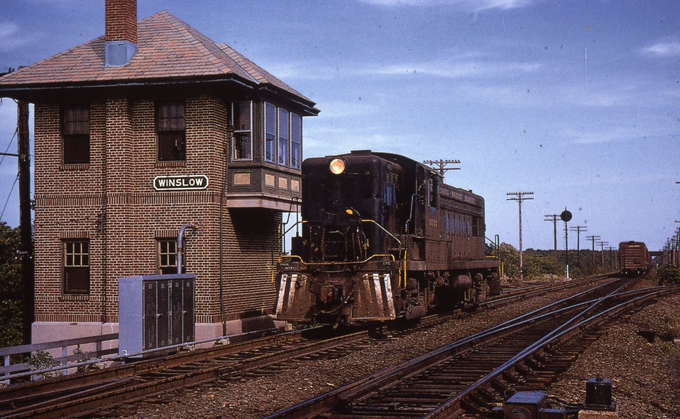
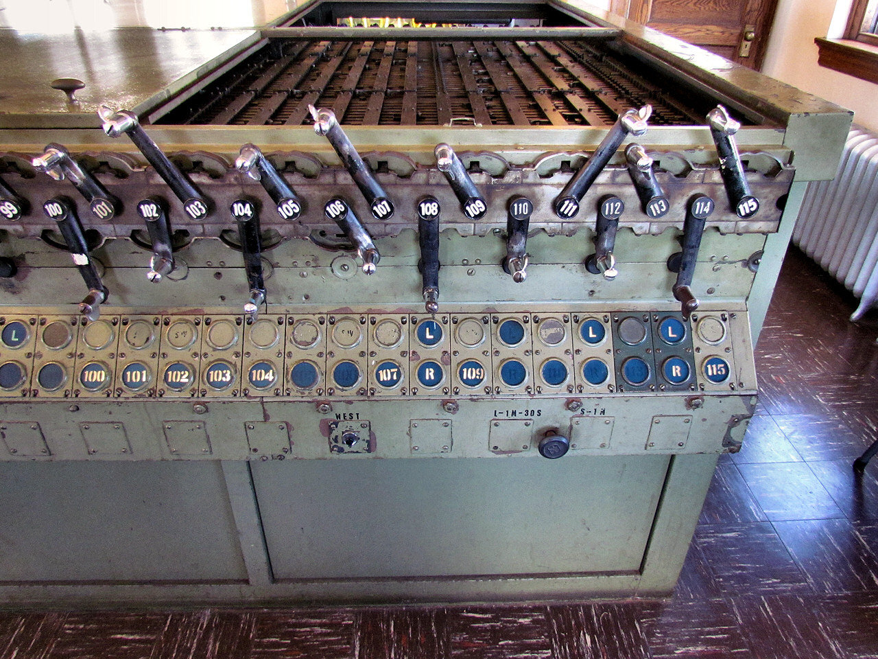
Having once hosted the fastest scheduled trains in the world, by the 1970's the PRSL Main Line to Atlantic City was a shadow of its former self, seeing a paltry peak direction service of ~3 daily round trips. By the late 1960's, the a double tracked, cab signaled main line constructed to PRR standards had been reduced to a single track with manual block operation south of Winslow Jct. In 1983 NJ DoT threw in the towel when Conrail stopped providing commuter rail contract services and all remaining signal infrastructure on the line was switched off and abandoned in place. This created a bit of a collector's gold rush with my then future shop teacher making away with an entire PRR position light mast signal and a single fallen pole providing my own family with decades' worth of giftable insulator paperweights. 


In 1985 Mr. Hammell would find this semi-abandoned rail line with 40 odd miles of green glass insulated pole line just a few miles from his front door. I am not sure what his early collecting methods would have involved, but about 5 years later the route would see a complete reconstruction with modern signaling that had no need for lineside poles. As you can see in the photo above not a single pole line pole remains. This means they were cut down in mass by a scrapper looking to recover the copper telegraph wire. This is a fairly common practice and I am convinced that a certain retiree happened to find himself at the right place at the right time to capture large numbers of the otherwise "worthless"  insulators that he would go on to assemble into a monumental yet underappreciated work of roadside art. 

Insulator Ranch was one of those local institutions that seemed destined to last forever until suddenly it was gone. I never got any of my own high quality photos of the installation or spoke to Mr. Hammell or even had whichever car I was in slow down or stop. I am assuming that the collection found some sort of home as a lot of 10k+ green glass insulators would be certainly worth money, but it still goes to show that institutions are run by people and people get old and die. The next time you see some unique railfan house, don't be so sure that another member of the community will step up to purchase it when the time comes.

Friday, March 10, 2023

Look For The Union Label

The Union Switch and Signal M3 family of electric point machines set the standard for performance and reliability, however entering into the catalogue around 1953, the M3's design and technology have long since gone off patent and are free for fly by night competitors to copy. Today we will take a quick look at the US&S trademarks as applied to their M3 family as well as the marks of imitators so you can avoid getting scammed.


Before I begin I would like to state that the following is not an exhaustive list as I am sure there will be countless variations within the broad categories I will outline below. I have photos of hundreds of M3 family switch machines and I am just going to take the average and find the best examples.

First off is what I will call the small verbose branding.  We have a small USS trademark followed by three lines of text consisting of "US&S Co", "Made in USA" and what appears to be parent information cast into the lid of the circuit contact portion of the switch machine. I suspect this is the earliest design as it looks most similar to the few surviving M2 machines and would likely be within the 17 year patent period starting around 1950.

The next version sees the third line dropped reducing the text to just "US&S Co" "Made in USA".

This is followed by the large logo variant that keeps the 2 lines of text, but has a larger US&S logo cast into the detector box cover.

Next we have the boxed variant that features the late model boxed US&S logo followed by "US&S Co" and "Made in USA" on earlier 1990's vintage machines and then just "US&S Co" in the later ones that are being sold up to the current day.


Now that you've seen the real stuff, let's check out some of the fakes. At the top of the skeezy list is this M23 I found on the UP Moffat Tunnel sub without any branding at all! 😬

Our next imitator is made by Vossloh and sold as the VSM-24.

Some of these are branded JMI, which is a machining and casting outfit. I am not sure if JMI was making complete switch machines and had that business bought out by Vossloh or if JMI was just a subcontractor.

Here is one I unfortunately neglected to get a good photo of, a Patco Industries branded M23B. Patco industries is known for their rebuilding work and sells pretty much every part of an M3 for spares so I am not sure if this was built from scratch or just has a lot of Patco parts.  It's worth mentioning that the branded contact case cover is made from aluminum, not cast iron.

I have heard mention of a few other companies selling M3 family switch machines and of course there are the international variants like Westinghouse Brake and Saxby Signal Company, but these are all the photo examples I have. If you know of any others please let me know in the comments and if you have some photos you wouldn't mind sharing I can add them to the list! Just remember, if you are looking for a quality electric switch machine, just look for the Union label.

Saturday, December 10, 2022

Death by 1000 Cuts: The NYCT Subway Slowdown

 Starting in the 1990's, the New York City Transit Authority (NYCTA) started a process to slow down the largest subway system in North America, ostensibly in the name of safety. Over the next two decades the process, conducted slowly and out of public view, went from costing riders a few minutes here and there to triggering a full on capacity meltdown as the system, despite its decreased performance, benefited from record ridership. Transit Twitter and Blog personality Uday Schultz has recently completed an exhaustive history of the great slowdown and the science of transit speed control in general. It's a great read and starts with a zero based explanation of the NTCYA's trip-stop and timer based ABS signaling system up through the events that triggered the management action and the subsequent slide into dysfunction. Still, while this piece does a great job explaining why, it comes up a bit short explaining "why". So lets dive in a bit.

One shot GT timer signals added to CANAL ST interlocking before re-signaling.

In the early 2000's everyone in the NYC Subway fan community was aware of the performance decreases and would track how the NYCTA seemed to seek out any location where trains could get moving and just find ways to throttle service back to a plod. Even in locations with no infrastructural changes the trains were operated with an appreciable lack of urgency. The community was full of theories as to why this slowdown was happening and, to a lesser degree, why nobody seemed to care. After all other cities, even those with traditional signaling systems like Philly, Chicago and Boston, found ways to achieve brisk acceleration and top speeds of 55-70mph, making the 25mph crawl of the NYC Subway a distinct outlier. 

SEPTA Broad Street Subway Express train @58mph.

As Uday's article covers (read it now to avoid spoilers), the speculation the early 2000's fan community was both right and wrong at the same time. They were right in that most of their theories were correct.  They were wrong in that there was no one reason that bore primary responsibility for the problem. The newer equipment, up through R68, did have slightly better performance than those the signal system was designed for. The new composite brake shoes did have slightly worse performance than the old iron shoes. The system did rely on train operator rules compliance and related management thereof to ensure safety. Then, between 1991 and 1995 all of these factors combined in varying degrees to cause four significant accidents, opening the NYCTA up to both liability and public pressure.

Inbound Williamsburg Bridge ramp with carlength long grade timer blocks.

The response was similarly multi-pronged from slowing rolling stock down in both acceleration and top speed (55 to 40mph), ubiquitous use of intermittent speed control devices, curtailment of restricted speed operation and harsh punishments for trip stop engagement. Much of this action plan was implemented over a period of 20 years so casual riders didn't really notice the decline in performance. The cherry on top was that the intermittent speed control devices were then allowed to drop below posted thresholds making operators wary of even trying to follow the posted speeds. This is what caused the opportunity to get a skilled operator and a "good run" to vanish over the course of the 2000's, especially as the pre-90's workforce that learned to run trains without speedometers, gradually retired. 

All of this background leads to the real question, why did ostensibly high level management decide that such a drastic decrease in performance was acceptable? This is important because in an age when getting the public to *want* to choose public over private transport, the performance of public transport is increasingly throttled by policy leaving private transport as the only option that can attempt to offer speed and convenience. Well, lets put on our 1991 hats and see what management may have been thinking.

  1. The most salient factor was the long term plan to equip the NYC Subway with a full time ATC/ATO system, later realized with the selection of CBTC to replace the wayside signals, timers and trip stops. Investment in an end-of-life signal system would be wasteful and performance decreases could be argued as temporary.

  2. After peaking at 2 billion annual riders in 1948, the shift to non-urban living and private transport dropped ridership by over half with the peak of NYC's crime wave coinciding with the subways trough of ridership. The system was running at half capacity so "slightly" increasing trip times was likely not seen to be a big deal.

  3. Decades of disinvestment had caused the NYC Subway to fall into a prolonged state of bad repair. With limited funds compelled trading performance for safety.

  4. The threat of continued accidents was a political liability while small overall changes in performance would be unlikely to generate much if any notice let alone political pushback.

  5. The reliance on operator skill presented not only the continued risk of accident, but would also put up pressure on costs as said skilled workers had to be trained and retained. Uniform operations according to the speed control systems would make operators fungible and require a lower skill floor.

These 5 factors could be arranged multiple ways to create a compelling policy proposal to management. It would have taken an extraordinary amount of personal risk for any of the top officials to insist on maintaining performance standards when CBTC was right around the corner anyway. I think the decisive element was the NYC Subway consistently running at half capacity for over two decades. It's not even that signal system capacity *could* be reduced with little impact, but that the 900 million annual ridership seemed to be both a floor and generally baked into the city. If local New Yorkers were willing to risk their life to ride the system, an extra few minutes wasn't likely to deter them either. To some extent management was proven correct, their slowness campaign only became a problem after ridership doubled over the following 20 years.

If you want a take away its that reducing performance has, is and will be the go-to fix for even rare safety problems. We've seen this with PTC and we've seen this on other transit systems like SEPTA and WMATA. The changes are rarely publicized and the public rarely objects even as they unconsciously sour on rail transit and make the switch to private vehicles. After the service meltdown NYCTA did set up a speed improvement task force that has been fixing the mis-calibrated timers and raising speeds that were subjected to overly conservative calculations. Still, while the rollout of CBTC has allowed for increased performance profiles, it would be interesting to calculate if they match what was achievable by human operators working under a system with a slightly greater tolerance for risk.

PS: An interesting comparison can be had with how the UK responded to the Ladbrook Grove Rail Crash of 1999. The crash program to install TPWS at select locations was similar to NYCT's system-wide modifications, however as far as I can tell, it had minimal impact on train operation, perhaps in part of the UK's continued reliance of train drivers' compliance with rules to ensure safety, as opposed to technical mechanisms.

Saturday, September 24, 2022

The Evolution of the Improved Saxby and Farmer Interlocking

In the realm of railroad interlocking machines, what does this...

Have in common with this...

Well they are kind of the same thing, the latter just being an improved version of the former that does away with most of the sweat and tears. Just like dinosaurs evolving into birds, 19th century mechanical interlocking systems evolved into smaller and lighter form factors with more and more automation until the technology reached its ultimate dead end. It might seem that a Union Switch and Signal electro-pneumatic power frame is a completely different piece of kit than the "armstrong" monsters that came before, but if we lift the hood we can see how the past influenced the future.

Setting aside who invented what and when, by the end of the 19th century there were two common mechanical interlocking styles coming out of the UK. The Style "A" Machine used a vertically oriented interlocking grid where lever bars on the Y-axis would interact with locking bars on the X-axis via a system of tappets. This style is what tends up show up in books and diagrams as it is the easiest to visually digest. The other system was the Improved Saxby and Farmer Interlocking, this used a horizontally oriented locking grid with lever bars moving in the x-axis interacting with locking bars in the z-axis via dogs. Regardless of the terminology, the key takeaway here is that there were two primary interlocking systems and Union Switch and Signal wound up with the US license for the Improved Saxby and Farmer variety.


Above is an IS&F implementation at the abandoned Buffalo, Rochester and Pittsburgh Railway tower at C&M Jct near Du Bois, PA. We can see how the lever bars are engaged by rotating shafts. The shafts were in turn attached to cranks that were in turn engaged by rockers that changed the back and forth motion of the large interlocking lever into an up and down motion that then rotated the shaft, ultimately sliding the interlocking bar back and forth in the x-axis (if the interlocking conditions allowed). In the photo below we can see how the rockers engage with the cranks behind the row of levers on an more complete lever frame.

So what does this have to do with a Model 14 machine? Well if we literally lift the hood we immediately find the exact same style of longitudinal lever bars, just slightly smaller and more compact.


Because on "power" interlocking machines tower operators no longer needed large physical levers to throw the switch points via a long length of pipe, all the complex mechanisms needed to convert the back and forth lever motion into longitudinal motion can be replaced by a miniature rotating crank. 


In case you were not yet convinced, the shafts that used to move the lever bars in the x-axis are still around to engage with the locking magnets controlled by the relay logic elsewhere in the tower.


In contrast, the other major type of North American pattern power interlocking machine, the GRS/Taylor "Pistol Grip" type, used the vertically oriented type of locking grid.


This horizontal vs vertical orientation explains why the largest Style "A" type frames were often in tall/narrow buildings, like STATELINE while the largest IS&F frames were in squat buildings such as DOLTON JCT.

STATELINE Tower Outside

STATELINE Tower Inside

DOLTON JCT Tower Outsde

DOLTON JCT Tower Inside

The US&S "Model 14" type interlocking machine was not even the final iteration of the Improved Saxby and Farmer type interlocking! That distinction belongs to the Westinghouse Brake and Saxby Signals Style V machine developed for the London Underground in the 1950's and used as late as 1967 for the all new London Victoria Line. The Style V was a Model 14 style locking bed turned on a vertical orientation with the levers being remotely actuated, typically using compressed air, allowing the interlocking to be remote controlled. I will probably give Style V's their own post at some point, but I wanted to give them a little shout-out in this context. Here we can see a Style V in action a bit after 1:31:25 in a 1960's Victoria Line construction public information film.


In its time railroad signaling was at the vanguard of high tech right along with the telephone system. With the pace of technology today, it is hard to believe that the concept of IS&F mechanical interlocking would be in use from before electric traction was invented up through the ATO equipped Victoria line. I guess it will sort of be how flavors of Z80 microprocessor will be in mainstream use, decades into the future.

Sunday, March 1, 2020

Right Hand Rule - How De-Regulation Ruined US Signaling

Why the US railroads seem to go from having a pathological need to mount their signals to the right hand side of the tracks they governed, like this...


Or this...


Or even this...


To, seemingly overnight, just doing this...


Well in 1939 most locomotives provided the engineer with visibility like this...


So in 1939 the ICC decided to legislate the obvious and required that all railroad signals be situated to the right hand side of the track they governed.  Of course the usual system of waivers and grandfathering applied so that left hand running lines such as the CNW didn't have to rip out its fireman-side signals, but all of that created barriers to cost cutting, even after the 1960's rolled around and all of the main line steam locomotives had been retired. 


By the 1980's, chopped short hoods on the F end had been the norm for the better part of two decades with only a few out-layers like the Southern, still holding on to the practice.  In 1985 the ICC successor, FRA decided that the Right Hand Rule was obsolete and railroads could put signals on whichever side of the track they wanted. 


The effect was immediate with back-to-back masts replacing split masts automatics and end-of-siding signal bump-outs becoming some sort of vestigial organ. Bracket masts, the go-to low cost option for bi-directional automatics on two track main lines were hit particularly hard along with the two track automatic signal bridge.  Multi-track cantilever signals have hung on, but only in areas of restricted visibility like curves.


Now in Europe many of the right (or left) hand replacement requirements are either still in force or at least still practiced by the state owned railways and as such there is much more diversity in the signal mounting systems, typically in the form of signal bridges.  It just goes to show how important the regulatory environment can be for something as esoteric as signal diversity.

Monday, January 14, 2019

Signal Videos from the 70's, 80's and Beyond

I don't tend to seek out railroad compilation videos, even historic.  They typically consist of about 10-20 cuts of some freight train passing with various "heritage" units on grainy VHS.  Any signal or interlocking content is fleeting and involves sorting through a lot of cruft.  Well after a recent content drop in the later two months of 2018, the Railroad Media Archive has become a major exception to the rule. I first noticed it earlier in the year when it posted 17 minutes of color 8 or 16mm film from a PRR cab ride between Columbus and Cincinnati on a route that is now mostly a rail train.  Signals and interlockings are definitely the focus and one can really see how properly focused PRR Amber Position Lights really pop.  At Cincinatti the person even got some footage in the still active Tower A.


There is also posted two explicit interlocking tower videos that have all sorts of interior video demonstrations of interlocking machines including one off-brand pistol grip machine from the B&O/EL Sterling tower that I had even never seen before.  The operation of the machine even comes with sync sound!  A real feat in the age of film. There are a whole bunch of other towers covered with demonstrations of CTC machines, table interlockers, mechanical lever plants and even the GRS N-X machine at F Tower in Fostoria.


There is another video that exclusively deals with the old NS tower in Lima Ohio, including a demo of the US&S Style S machine there.


Finally this guy seemed to be in the right place at the right time, even up into the 1990's with video of SO interlocking in South Fork PA just before the tower was closed and a ride in a Capitol Limited dome car as is traversed the Conrail raceway into Chicago between HICK tower and ENGLEWOOD with all of the old school PRR and NYC signaling still in place.


Like I said, you won't be disappointed. Check out all this guy's stuff. Be warned, it might make you a little sad to see how much amazing retro technology has been lost since just the 1990's :-(

Sunday, July 24, 2016

It's the 80's! (Do a lot of coke and design a bad signal.)

By the time the 1980's rolled around the dominant signaling providers in North America, US&S and GRS, were facing unanticipated competition from a variety of upstarts like SafeTran, Harris and others, that were making the incumbents 1920's vintage cast iron product line look a little long in the tooth.  The result were a pair of odd designs that entered the stage and then quickly exited with nobody really talking about them ever again.  The interesting thing is that both major manufacturers seemed to take the opposite lesson and in the end they both learned different things.

First up we have General Railway Signal's three lamp traffic light style signal.  Previously GRS has been the leader in modular signal design with their Type D signal having one lamp and the ability to be stacked as high as needed.  Seeing US&S with its successful 'N' series of linear multi-lamp signals, GRS added this rather low cost clone to its lineup.  Can you can see from the photos it was very low frills except for a snazzy block style GRS logo on the back.  The only nod to progress appears to be rust resistant aluminum construction.


These signals are quite rare with the only notable installation being the LA Union Passenger Terminal and this attests to their general success in the market.  It seems that GRS was stung by this turn of events as they basically exited the market for signal hardware aside from long running line of rapid transit signals that continue to be sold under the Alstom brand. 

As I said before, US&S took the opposite lesson and decided to add a modular signal to its lineup to supplement the N series that was forced to use a round marker lamp for single light situations. What they came up with is best described as...bizarre.


Yes they thought the best solution for a stackable modular signal lamp was a round housing. Stacking support was provided by an external frame that came in 1, 2, 3 and 4 lamp configurations.  Still, you have to give US&S a point for versatility since these units could also be arranged on a circular target signal in a 3 lamp configurations.  Again note the Plain Jane construction which was common in the high labor cost/pre-CNC period.


Needless to say these were also a flop with the largest concentrations appearing on the Pittsburgh Light Rail network and on the METRA Electric Division.   However, unlike GRS, US&S chose to keep fighting the low cost upstarts and re-designed their modular signal to be the squarest square you have ever seen.


Overcompensation much?

Anyway, if anyone knows the actual model designations of these signals please let me know and I'll update the posts. Also, I assume that the design and market life of these signals probably went beyond the 80's on one side or the other, but that would make less of a compelling title.

Sunday, November 29, 2015

Hall Disc (aka Banjo) Signals Explained

If a book on North American signaling has a chapter before semaphores that covers stuff like, flag signals, ball signals and tilting targets, Hall "Banjo" signals are often included since they not only look strange, but have also been extinct in the wild since the 1950's.  While hardly forgotten to history, most sources tend to focus on how these signals worked mechanically, as opposed to how they were employed functionally.  The result is that unless one really digs, you are unlikely to know much more about a Hall banjo signal than it was sort of like a searchlight and sort of like a semaphore.  Today I hope to clear up some of the ambiguity surrounding these dinosaurs of North American signaling.


First, how do Banjo signals work?  Hall disc signals were one of the first types to work in conjunction with the revolutionary idea of the track circuit.  Now I have seen some sources associate Banjo signals with time separation systems, and while they could certainly be used in such a capacity, I am going to focus on their use in automatic blocks.  A disc signal (patented ~1869)  is basically a searchlight mixed with a semaphore, before the advent of either electric lighting or electric motors.  Like semaphores, disc signals have a large day indication (the disc) illuminated by natural light, and a small night indication illuminated by an oil lantern.  Like a searchlight, there is a magnetic armature that moves in response to an electric current. When the signal is energized the disc and filter are moved away from the day and night signals changing them from red (or yellow) to clear (or green).  If you can't tell where the disc goes, it is moved up to the 10 o'clock position where a small corner can still be observed.

Some say this is where the term "Clear" signal came from.  Argue in the comments.


The above photo shows a pair of banjo signals in their "clear" state, the colored disc moved up and out of the way to allow daylight to show through. The two state disc signals could be made to display three signal states be using either a distant-home configuration (as is still popular in Europe) or by mounting two heads on the same mast, one displaying Red and Clear, the other Yellow and Clear.  Clear/Clear = Clear, Clear/Yellow = Approach and Red/Yellow = Stop (and Proceed).


This rare color photo shows a Hall disc signal actually doing its job.  As you can see the colored discs are actually pretty effective.  In a time before electricity, these would be a high tech alternative to mechanically operated semaphores. This also explains why Banjo signals are so often associated with the Reading system.  In the late 19th century the Reading was an extremely wealthy railroad and would be able to afford something that would be like CBTC today.  As ABS became more prevalent, disc signals fell into the same category as 2-position lower quadrant semaphores,a commodity technology which lasted into the 21st century on some former Southern Pacific lines.


Now it is time to put together the final piece of the puzzle.  Above we see an arrangement that was only possible within a fairly narrow sliver of time.  Reading Hall disc signals are on the same mast as mechanically operated semaphores.  What is going on here?  Well the disc signals that are designed to work with low power, primitive track circuits are providing an automatic block signal indication, while the mechanical semaphores are worked from a nearby interlocking tower providing the route protection. 


Here we see a slightly different scenario where we have two position semaphores for trains moving torwards the camera, the top mounted semaphore for a straight route, the middle semaphore for a diverging route and then the low mounted call-on signal.  Then we see the Banjo for trains moving away from the camera as ABS exit signals. The semaphores can be directly controlled from a mechanical lever frame, displaying either Clear, Medium Clear or Restricting, and any ABS modifications given by the Baljo signals when the train departs the interlocking limits.  So Medium Approach would be Medium Clear entrance to Approach exit.

I am by no means an expert on all the ways these signals were employed, but I do know that one can't simply dismiss them as proto-searchlights or glorified semaphores as is often the case in so many books and museums.  Hall disc signals needs to be understood in the context of a manual block world devoid of even the basic electronics that would revolutionize railway signaling in the 1890's.  They were cutting edge technology employed by only by those railroads that could afford to be early adopters.