A blog devoted to explaining the ins and outs of North American railroad signaling, past, present and future. This blog seeks to preserve through photo documentation the great diversity and technical ingenuity of 20th century signaling and interlocking hardware and technology. Related topics cover interlocking towers and railroad communications infrastructure.
Note, due to a web hosting failure some of the photos and links may be unavailable.
Despite its status as an evil empire, Union Pacific has a surprising amount of legacy signaling on its premier transcontinental route between North Platte, NE and Ogden, UT. Sliding just under the falling boom of Safetran scallop-shells and off-brand LEDs, in the late 1980's Union Pacific chose US&S hardware for its overland route CTC project. This includes style N single housing color light signals and their extra large "elephant ear" backings. Similar to multiple projects on the Seaboard part of CSX, the Union Pacific elephant ears managed to survive the 2010's PTC push with the overlay being applied without signal or signaling replacement.
Well it seems that one major shortcoming has these survivors on somewhat borrowed time. They are still connected to a pole line and here we can see that at least near Sidney, NE, some of the 80's signaling is being removed. If this is a localized project or something larger remains to be seen, especially if UP's capital budget is constrained in future years.
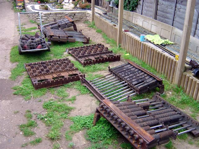
This blog devotes a lot of coverage to the plight of the pneumatic switch-point machine and its long decline since its heyday between 1930 and 1955, but apart from the ka-chug--woosh sound, what makes them distinctive? Well its actually their simplicity compared to their electric counterparts and its that simplicity that made them so competitive with electric point machines despite the overhead of making and distributing compressed air.
Above we see a Union Switch and Signal model A-5 pneumatic point machine. (An earlier A-1 model also existed and you can tell them in photos because the housing looks like a miniature Quonset hut.) At one end we see the double acting air piston, at the other we see a connection for the control circuits and a blind tube without an air piston, and in the middle we have a fairly plain looking box.
Next lets quickly go over a standard power operated switch layout using some casual terminology. Moving away from the camera we have a stretcher bar that provides rigidity. Next is the throw mechanism that transmits force from the point machine to the points via a rod. This uses a slack coupling so the point mechanism can begin to move and break the static friction. Finally we have the detection rods that accurately detect if the points are hard against the stock rail and communicate that state to the signaling system.
Exposed US&S A-5 pneumatic point machine.
The mechanism can be set up for operation from either side.
Here we see a naked A-5 without its cover on showing off the simplicity of the action. The air piston connects to an action bar which runs through a crank mechanism that transmits force to the point rodding and also its positional state to the circuit controller.
The crank (left) and circuit controller (right).
The coupling between the air piston and the action bar.
The air piston, these came in 3 inch and 5 inch diameter models.
The throw rod couples to the crank assembly. In the photo below this connection is the bolt hole on the stubby arm below the pivot pin. The detection rods sit under the circuit controller have the golden coated nuts on them.
The circuit controller pulls double duty, detecting both the position of the points for the signaling system and also the position of the action bar / air piston, which is sent to the style CP air value unit to cut the flow of air and dump the pressure in the piston. We can see the hind end of the action bar that is given room to push outward under the covering.
The upper two rods provide the actual point detection while I believe the lower rod that extends through the mechanism provides a physical locking function in conjunction with the action bar. When this technology was new that rod would serve the role of the familiar facing point lock.
The goal of the mechanism is to lock the switch point securely against the stock rail even when air pressure in the cylinder has been exhausted, but allow smooth movement of the action bar and points when air is admitted to move the piston. A similar concept is present in firearms where the bolt is locked against moving rearward by the force of gases in the chamber, but is able to be easily unlocked via motion in a different axis.
While I have personally captured video of an A-5 point machine performing a throw cycle, it only showed the points moving along with the admittedly cool sound. However I recently came across a different video from a UK rail museum that has their own flavor of a US&S A-series set up for live demonstrations. Still popular on the London Underground, these instances are commonly used without the protective cover which allows visitors to actually see how the mechanism functions. This flavor of Westinghouse point machine is intended to be set between the rails and has the throw rods moving through the mechanism. The extra circuit controller on the back provides feedback to the pneumatic value.
Every so often I mention the Westinghouse Brake and Saxby Signal Company which was the result of the British Commonwealth's Westinghouse Brake Company purchasing the then dominant UK railway signaling supplier Saxby and Farmer in 1901. For those of you who are unaware, George Westinghouse's claim to fame was the invention of the automatic railroad air brake and he set up corporate entities in both the US and overseas to market his produce. In an early example of corporate synergy, Westinghouse also became involved with railway signaling, either directly producing signaling hardware or owning a signaling subsidiary in many markets. Because there is little sense in reinventing the wheel, the Westinghouse corporate empire would cross-license signaling technology between its various arms. This is how US&S became the supplier of the Improved Saxby and Farmer type mechanical lever frame in the United States and how WB&SS Co would come to sell a power interlocking machine awfully similar to what would become the Model 14 family sold by US&S.
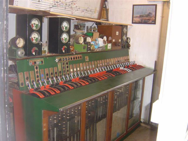
Balham Signalbox Style L Power Frame
As railway signaling moved from purely mechanical to incorporate automatic blocks, electric signals and power operated point machines, interlocking machines effectively became hybrids with both mechanical and electric locking. 19th century mechanical methods would continue to provide the route locking, while magnets and solenoids would lock the levers electrically based on track or switch position circuits.
Electric locks on a traditional "armstrong" type lever frame.
Since safety critical railway signaling relays were quite expensive, signaling suppliers had an incentive to carry out as much logic as possible in the mechanical layer. Therefore even "power" interlocking machines like the GRS pistol grip style or US&S crank lever style still made use of miniaturized mechanical locking grids.
Westinghouse owned Union Switch ad Signal had already been the North American licensee of the Improved Saxby and Farmer mechanical locking system and has been using it in its crank style power interlocking machines since the 1890's. In 1901 the newly minted Westinghouse Brake and Saxby Signal Company was suddenly in a position to employ US&S's innovations in Commonwealth countries and came out with its Styles A and B interlocking machines, localized for British signaling tastes.
WB&SS Co Miniature Lever Frame in British Service
Like the crank (ie "Model 14") style interlocking machines in North America, the Westinghouse power frames had three distinct logical components inside the box. First, a mechanical locking grid of the S&F type handling route locking. Second, locking magnets that would lock lever travel based on the state of the electric relay logic. Third, electric contact spindles that would make or brake electric circuits depending on the position of the lever.
Style K frame with mechanical locking grid.
Style K frame contact spindles.
A route conflict would result in a hard lock as steel bits in the locking grid would physically block movement. An electric problem like points out of correspondence or an occupied track circuit would create a soft lock as the lever was stopped by magnetic latches interacting with a rocker arm on the lever spindle. Anyone who has visited HARRIS tower and its functional Model 14 knows the difference in feel between hard and soft.
Magnetic "soft" locks on a Model 14 machine.
All of this was fine until 1929 when the 23 ton weight of 311 lever London BridgeStyle K interlocking machine made Westinghouse Brake and Signal question the sustainability of the technology. Unlike North American pattern machines, the British pattern was less lever efficient, needing more physical levers to carry out the same functions. This not only created a weight problem, but also a size problem as the locking grid dimensions grew literally by the square of the lever count. While American railroads had the space to build beefy towers with wide dimensions, the "early adopter" British railways had harder clearance constraints, especially in major cities where large power frames were most likely to be built. For example the aforementioned London Bridge signal box had to orient its locking bed vertically, making the tower an extra floor taller.
London Bridge Signalbox
The solution to this was the Style L frame. Externally the Style L looks exactly the same as the Style K, however internally it is quite different with the mechanical locking grid being completely done away with and replaced by electric locking. the Style L existed as yet another step between the purely mechanical interlockings of the 19th century and the all-relay plants that would ascend in the 1950's. However for anyone wondering why an electrically interlocked plant would even bother with clunky miniature levers, there are some advantages. First it maintains a familiar UI and reuses many of the components that were already in production. Second, it still reduces the number of high cost safety critical railroad relays. The latter is not entirely obvious, but an electro-magnet that unlock a contact spindle that a human then turns, is performing many of the same functions as a vital relay without the same need for precision manufacturing. The website covering Westinghouse power frames has both patent and part information so I'll leave digging down into the fine details of how this electric locking was carried out as an exercise to the reader.
Style L parts
Style L restored
Style L relay locking logic
The Style L completely displaced the mechanically locked style B and K frames on the main line UK rail network with a burst of new deliveries being made to the British Rail Southern Region between 1948 and 1953. Additional frames were delivered to South Africa up until 1960 with a final BR frame delivered in 1962. An interesting ramification of the Style L all-electric logic was a far greater degree of adaptability than those with mechanical locking. In North America, all railroads (except naturally the PRR) had to hire US&S to perform major modifications to the mechanical locking grid. However the Style L electric locking could be modified without the need for specialized tools and British Rail was able to manufacture quite a few "new" Style L plants using left over components or even spare frames obtained for redundancy purposes during World War 2. Even after retirement from main line service, both heritage and miniature railways have been able to adapt surplus Style L equipment for their own track layouts.
The final act of the Westinghouse power frame would play out on London Transport in the form of the mechanically locked Style N and Style V frames as their modest lever counts and subterranean placement didn't trigger the same sort of weight issues seen on the main line railroads. In fact, the last Style V frame, think a Model 14 automated by pneumatic actuators) was installed on LT in 1993! (Which goes to show just how wedded the British were to mechanical technology.) With the closure of Wellington A Signalbox earlier in 2025 and Liverpool Lime St in 2018, the last active Style L outside of preservation might be the signalbox at Maidstone East, which was fittingly the last new built Style L delivered in 1962.
A while ago I posted the first part of my coverage of the Pennsylvania Railroad's 1929 CORK interlocking tower in Lancaster, PA which covered the tower's history and the layout of the interlocking on the PRR's Main Line. Today we cover the tower itself, heading inside to see how it functioned in both its pre and post re-signaling phases. The exterior photos date from 2005 when the interlocking complex was in the process of being resignaled.
To recap, CORK interlocking and tower were constructed as part of the 1929 Lancaster station project which moved Lancaster's busy passenger depot away from a downtown alignment with slow speeds, lots of grade crossings and partial street running. The resulting interlocking plant spanned approximately 3.3 miles of main line track, which was an outlier for early 20th century direct wire controlled interlockings in North America. Like the contemporary Lancaster station. CORK was built of a dark brick and featured a prominent bay window sheathed in copper cladding.
The tower had one auxiliary building that housed the primary compressed air plant and was situated on the south side of the tracks in line with the extreme west ends of the high level station platforms. The tower had an internal staircase with the shelf type relay room on the first floor. With its brick construction and slate roof, the tower was in excellent physical shape as it entered the 21st century.
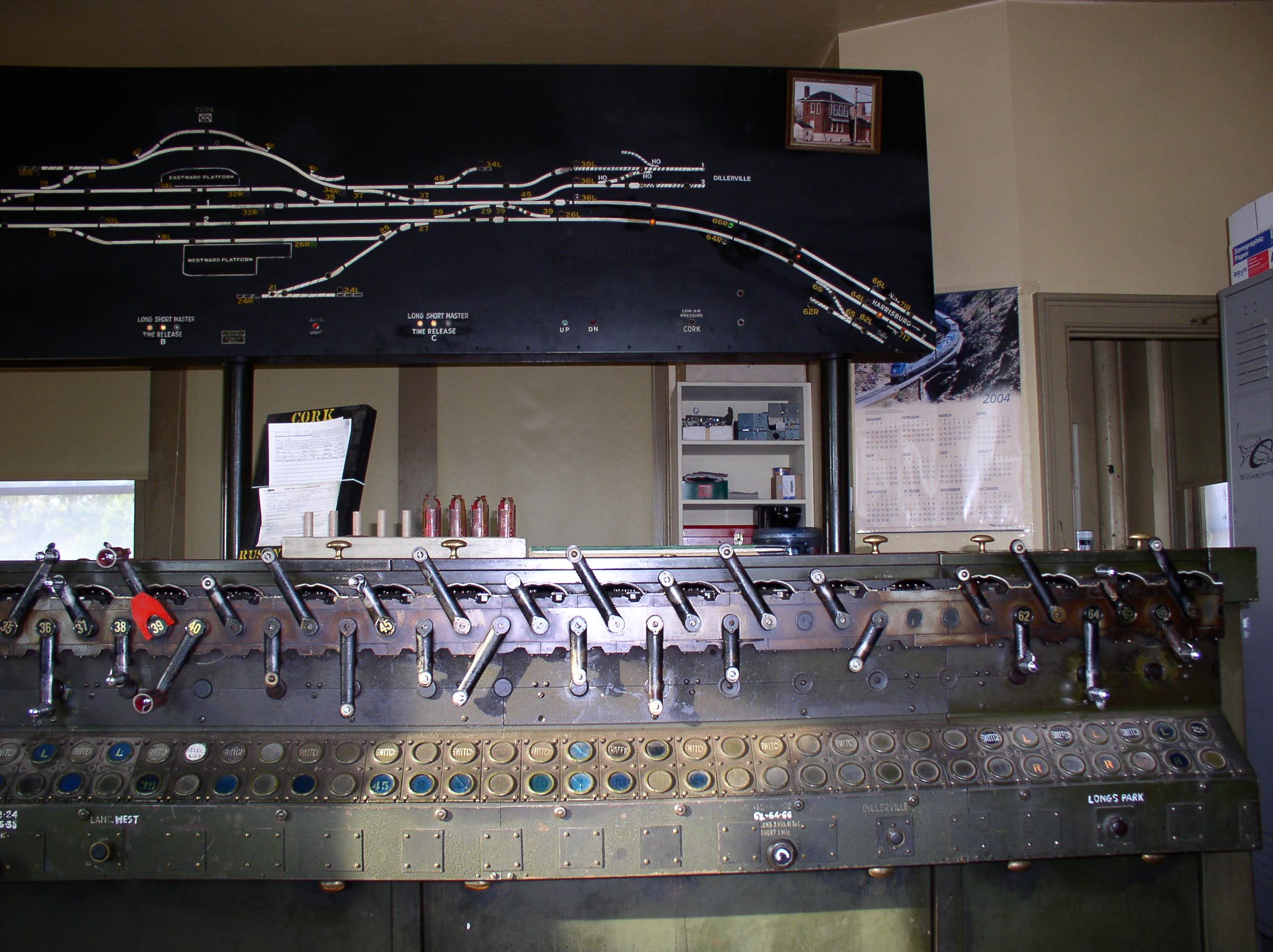
Heading inside the tower we find a typical layout with the operator's desk sitting in front of the US&S Model 14 interlocking machine. A defect detector readout and overhead catenary section breaker control panel are to the operator's right with the lockers, clock and old telecom plugboard sitting to the left. One interesting feature is that the room has retained its original 1929 vintage overhead lamp fixtures.
The operator's space is feels like a more cramped version of HARRIS tower with less space around the interlocking machine on all four sides. The gap between the scoreboard style model board and the rear aligned internal staircase is particularly small. As with other PRR Main Line towers, lever blocking devices are stored on top of the interlocking machine and the bathroom is in the left rear corner. Also note the location of the refrigerator, notice board and train order hoops.
The sprawling CORK interlocking plant was controlled by a relatively modest 67 lever interlocking machine with 49 active levers in its 1960's configuration consisting of 23 levers for switches, 23 levers for signals, 2 levers for electric switch locks and 1 crossing lever for the Reading's Lancaster Branch diamond crossing. The plant was divided into three timer zones, A, B and C with the A timer handling the Conestoga section, the B timer the central Cork plant and the C timer the Reading crossing. The short run was 1 minute with the long run being about 5 minutes and 30 seconds. The tower also had 4 horns for Conestoga, the tower itself, Lancaster West, Dillersville yard and the Reading crossing (Longs Park).
One interesting feature was the presence of Rusty Rail tabs instead of the more usual placard. Besides that the levers were of the standard US&S crank type.
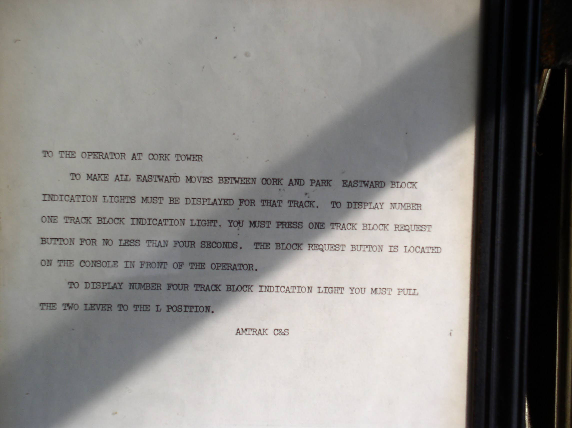
Although CORK's model board was a standard PRR illuminated type, it had several interesting features features. Grade crossing status lights were located at either end of the board to indicate the activation status of the Irishtown Road (east) or Eby Chiques (west) crossings. There were three low air alarms for East and West Conestoga in addition to the Cork main plant. In the post-1960 era two block indication lamps were added for tracks 1 and 4 eastbound. These had some interaction with PARK tower to the east as well as the intervening temporary block station at LEAMAN with track #1 being lit by the regular 2 lever and track #4 by a button on the operator's desk console. Best I can tell this was some technical method to prevent conflicting movements beyond what would be afforded by train orders and the dispatcher. Finally the most endearing model board feature was a framed photo of CORK tower itself that is also present in photos from c. 1992.
Union Switch and Signal had always maintained a bit of a home field advantage around Pittsburgh, with the local railroads, most notably the PRR, preferring their products. As railroads grew larger, this hold field advantage grew smaller, mostly applying to the home town Port Authority Transit light rail Union Railroad. For example, both were some of the few customers of US&S's 80's pattern modular signals that were attempting to compete with Safetran's scallop shells.
Well, it appears that since the purchases by Ansaldo and more recently, Hitatchi, US&S has lost its local influence and the Union Railroad is now installing L&W brand signals from Missouri.
The URR was always a bit of a potpourri of signals, but the 80's US&S modular fare always stood out.
Electrically locked switches are the red headed stepchildren of the interlocking world. Not nearly as glamorous as their powered brethren, and rarely ensconced within the safe confined of interlocking limits, electrically locked switches help make North America's efficient bi-directional main tracks possible. For the uninitiated let me clarify that while powered points are also "locked" by something involving "electricity", when I say electrically locked switch, I am referring to a hand throw switch that has some sort of electro-mechanical interlock that prevents operation in the face of an unsafe condition.. E-locked switch hardware is provided by both major North American signaling lineages (US&S and GRS) and in today's post I am going to provide a quick overview of the broad e-locked switch families and how they work.
In the beginning if a railroad didn't want the expense of interlocking a switch with signals via a staffed tower their choices were to assume the risk of trains not being able to get stopped by an improperly set hand throw switch or ensure that all hand throw switches were in the trailing configuration, something that required at least two single direction main tracks. As track circuiting became the norm, operating a hand throw switch could shunt the circuit like any other obstruction, but this wouldn't be much help if an approaching train had already passed the previous block signal.
Unprotected hand throw switch equipped with a track circuit interrupter.
The easiest solution is procedural control where the employee shunts the track circuit, waits a proscribed period of time, then throws the switch. However where the railroad desires a bit more assurance than a padlock and watch, the electric switch lock comes into play. The concept is simple, use a solenoid mechanism to prevent switch operation until allowed by the signaling system. This can include direct dispatcher/operator control, like from a lever on an interlocking machine, or conditions such as track circuit occupancy or a rundown timer. In general direct control is the less common of the two as within interlocking limits railroads tend to just pay a bit more for power operated switch machines.
US&S TM-20 switch stand without an electric lock.
At this point I want to take the time to clear up a misconception regarding electrically locked switches. Above is the US&S TM-20 hand throw switch stand. It kind of looks like a miniature point machine with wires going into it, a mechanism to work a pipeline connected derail and an extra locking bar. For years I thought this was an electrically locked point machine because it appears on main lines that tend to benefit from electrically locked points. However there is nothing in a TM-20 that provides for locking functionality. The cover on the end is just houses an integrated make/break circuit controller. So while this type of switch stand might look the part, the real e-lock is a bolt on component.
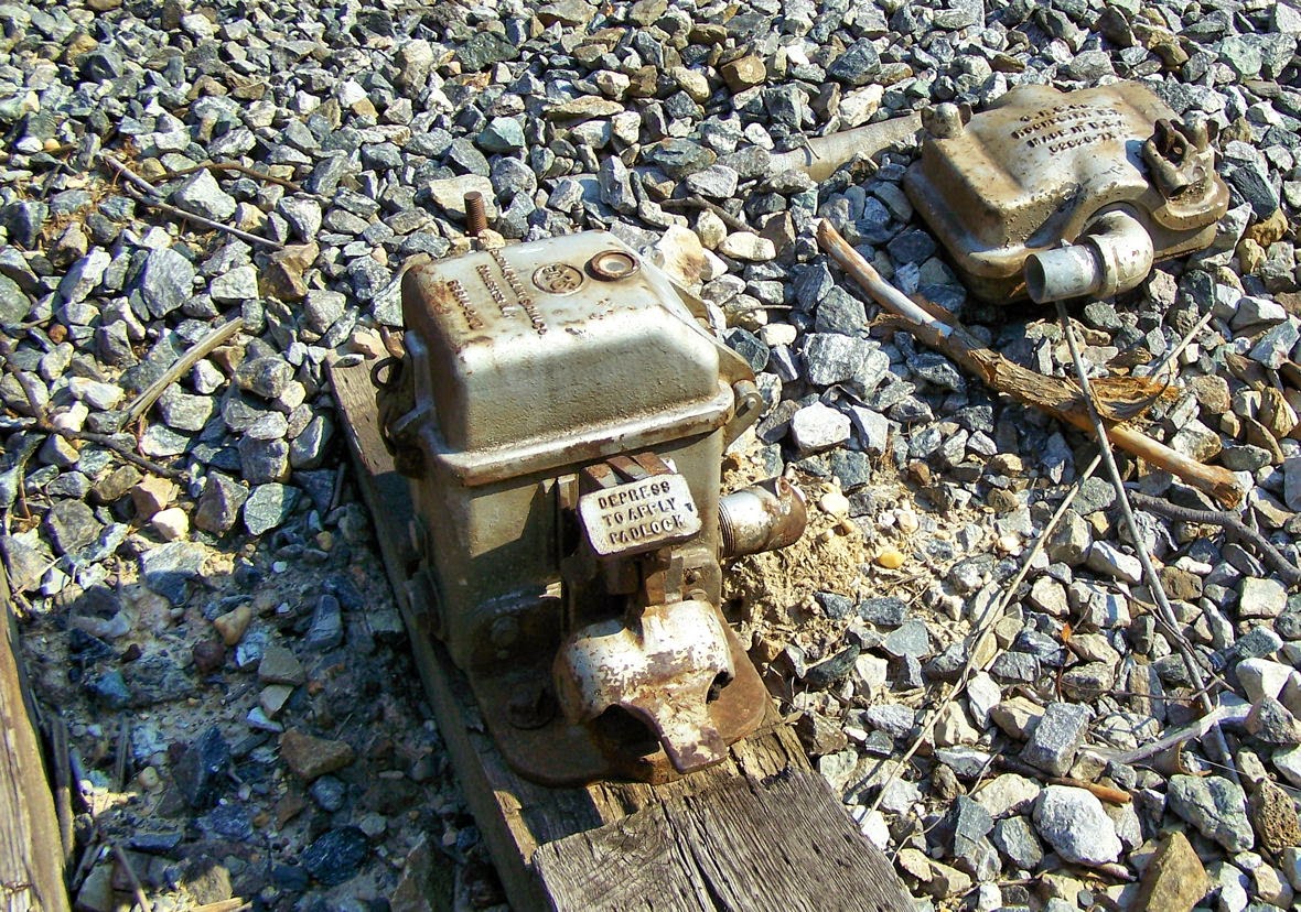
Abandoned GRS electric lock unit.
The E-Locks themselves come in two general forms, the plunger style and the pedal style. Each style is available from both vendor lines, but I want to discuss the pedal style first since it is the one paired with those TM-20 machines I just mentioned. The pedal style consists of a small box, separate from the hand throw point machine, which locks the hand throw switch arm in the desired position. The train crew's padlock holds down a small pedal. Removing the lock allowed the pedal to raise up, energizing the mechanism. In this state a small window displays either a green lamp if the switch is free to move or a red lamp if it is not. If a timer needs to be run, releasing the pedal starts it. Any timers and signaling relays are located in a trackside cabinet. When the lamp is green a second pedal can be depressed to unlatch the hand throw switch arm. Below is an example from the old CP-VO on the former Conrail Selkirk Branch where a direct control pedal type e-lock locks the throw arm of a basic dome type hand throw switch stand.
Interlocked e-lock hand throw switch stand within CP-VO.
Here we see a low profile US&S style lock device. Here we see a TM-20 with an SL-25 electric lock attached.
The SL-25 can be even located between the rails in a stand alone configuration and in this case uses a pipeline to lock two TM-20 point mechanisms on either end of an e-locked turnout.
Here we see the GRS answer to the TM-20 with an attached e-lock box. This example is located within the limits of CP-89 on the former Conrail Hudson Line and is released by a "lever" on the dispatcher's interface.
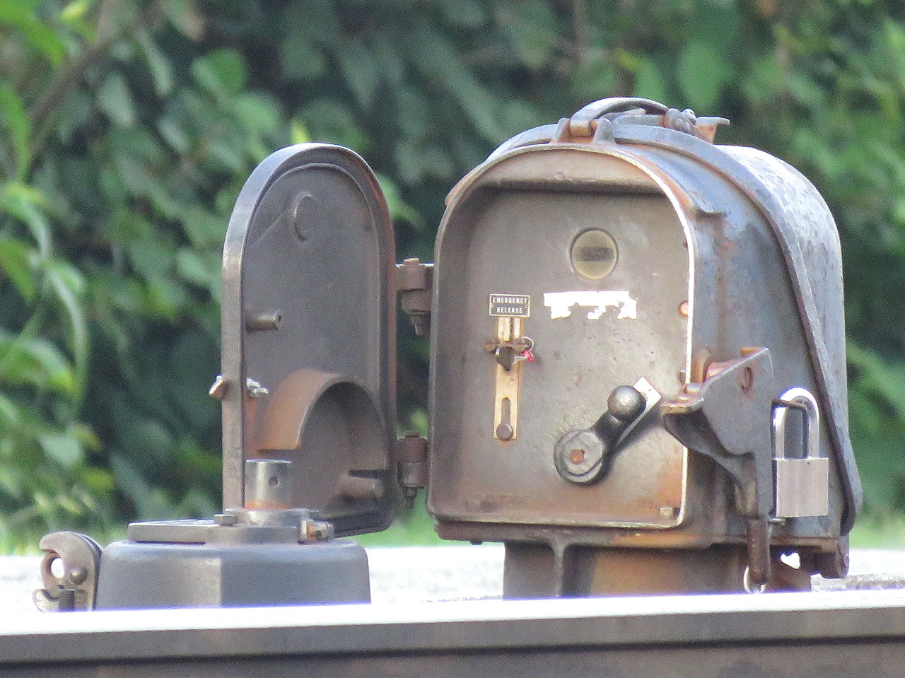
The plunger style is a bit more recognizable due to its more prominent form factor. The plunger lock consists of a little housing, sometimes on a raised pedestal, mounted adjacent to any type of hand throw switch stand. The trainman opens the little door and requests a release by moving a crank type lever from the lock to unlock-request position, similar to a US&S table interlocking machine. This engages the relays and timers in the cabinet and when conditions are safe, a solenoid releases and the crank is able to complete its travel, raising a metal plunger that is physically blocking movement of the switch point rodding in the process. The plunger is either directly below the housing or below the hollow pedestal, if present.
It is common to have both a short and long duration timer with short time (~30 seconds) applying when the main track is unoccupied and the long time (5-13min) applying when a main track train movement is possible. While short and long timers are not exclusive to the plunger type, the plunger type user interface makes them more apparent.
Another feature on the plunger type is the presence of a sealed emergency release button in case something goes wrong with the release logic. Breaking the seal and pressing the button allows for immediate release of the points. On the pedal type e-locks this functionality can be provided by an optional key switch.
Pedistal mounted plunger lock. Note the housing's similarity to a semaphore signal's.
These two types of e-locks are the bulk of what one will encounter in North America with the US&S and GRS equipment lines offering both form factors. It's actually pretty simple if you think about it, but if you don't want to take my word for it, here is a video from Mark Clay McGowan that describes the operation of each type in far more detail.
I hope you all found this interesting. I didn't get into the nitty gritty of identifying every exact model of lock, but now that you know what to look for, see if you can spot the slight differences out in the field.
.JPG)


