A blog devoted to explaining the ins and outs of North American railroad signaling, past, present and future. This blog seeks to preserve through photo documentation the great diversity and technical ingenuity of 20th century signaling and interlocking hardware and technology. Related topics cover interlocking towers and railroad communications infrastructure.
Note, due to a web hosting failure some of the photos and links may be unavailable.
I've mentioned this phenomena before, but in this day and age when a Class 1 appears to have "forgotten" about some bit of classic signaling its usually because they intend to sell the line or they are planning something much more drastic than a re-signaling project. Usually this is complete signal removal (I'm looking at you Buffalo Line), but in the case of the largely PRR signaled NS Fort Wayne Line west of Alliance, NS apparently had in mind a radical single tracking project.
Currently the Fort Wayne Line is double track from the Cleveland Line split at CP-ALLIANCE (MP 82) to CP-MACE (MP 110), CP-ORR (MP 124) to CP-BIG RUN (MP 138) and CP-MOHICAN (Mp 157) to Crestline (MP 188). The line has always been a step child after lost traffic was diverted up the Cleveland Line to the Chicago Line. I would not be surprised if the line had managed to stay PTC exempt due to light traffic. The current Conrail era CTC signaling dates from the late-1980's and matches that installed on the former PRR Middle Division.
In 2022 NS released the following single tracking plan that would result in the likely retirement of all remaining PRR position lights on the route and also bring the curtain down on the last major instance of PRR signaling on NS.
Retirement of selected double main line track operations into single signaled bi-directional track (Rule 261).
Approximant limits of project will be PC 84.8 to PC 188.3 on the Fort Wayne line of the Pittsburgh division.
Retire one main track at mile posts PC 84.8-96.7, 157.3-160.1, 161.9-169.4, 178.0-188.3. Change method of operation at mile post limits of 160.1-161.9, 175.1-178.0 to Non Controlled Track.
The good news is that as of 2022 no movement has been made on activating this plan and the recent manpower and capacity problems might cause some change of heart. Regardless, get out to Ohio and get your photos ASAP.
In the realm of railroad interlocking machines, what does this...
Have in common with this...
Well they are kind of the same thing, the latter just being an improved version of the former that does away with most of the sweat and tears. Just like dinosaurs evolving into birds, 19th century mechanical interlocking systems evolved into smaller and lighter form factors with more and more automation until the technology reached its ultimate dead end. It might seem that a Union Switch and Signal electro-pneumatic power frame is a completely different piece of kit than the "armstrong" monsters that came before, but if we lift the hood we can see how the past influenced the future.
Setting aside who invented what and when, by the end of the 19th century there were two common mechanical interlocking styles coming out of the UK. The Style "A" Machine used a vertically oriented interlocking grid where lever bars on the Y-axis would interact with locking bars on the X-axis via a system of tappets. This style is what tends up show up in books and diagrams as it is the easiest to visually digest. The other system was the Improved Saxby and Farmer Interlocking, this used a horizontally oriented locking grid with lever bars moving in the x-axis interacting with locking bars in the z-axis via dogs. Regardless of the terminology, the key takeaway here is that there were two primary interlocking systems and Union Switch and Signal wound up with the US license for the Improved Saxby and Farmer variety.
Above is an IS&F implementation at the abandoned Buffalo, Rochester and Pittsburgh Railway tower at C&M Jct near Du Bois, PA. We can see how the lever bars are engaged by rotating shafts. The shafts were in turn attached to cranks that were in turn engaged by rockers that changed the back and forth motion of the large interlocking lever into an up and down motion that then rotated the shaft, ultimately sliding the interlocking bar back and forth in the x-axis (if the interlocking conditions allowed). In the photo below we can see how the rockers engage with the cranks behind the row of levers on an more complete lever frame.
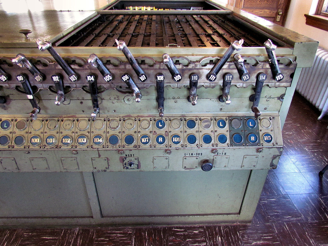
So what does this have to do with a Model 14 machine? Well if we literally lift the hood we immediately find the exact same style of longitudinal lever bars, just slightly smaller and more compact.
Because on "power" interlocking machines tower operators no longer needed large physical levers to throw the switch points via a long length of pipe, all the complex mechanisms needed to convert the back and forth lever motion into longitudinal motion can be replaced by a miniature rotating crank.
In case you were not yet convinced, the shafts that used to move the lever bars in the x-axis are still around to engage with the locking magnets controlled by the relay logic elsewhere in the tower.
In contrast, the other major type of North American pattern power interlocking machine, the GRS/Taylor "Pistol Grip" type, used the vertically oriented type of locking grid.
This horizontal vs vertical orientation explains why the largest Style "A" type frames were often in tall/narrow buildings, like STATELINE while the largest IS&F frames were in squat buildings such as DOLTON JCT.
STATELINE Tower Outside
STATELINE Tower Inside
DOLTON JCT Tower Outsde
DOLTON JCT Tower Inside
The US&S "Model 14" type interlocking machine was not even the final iteration of the Improved Saxby and Farmer type interlocking! That distinction belongs to the Westinghouse Brake and Saxby Signals Style V machine developed for the London Underground in the 1950's and used as late as 1967 for the all new London Victoria Line. The Style V was a Model 14 style locking bed turned on a vertical orientation with the levers being remotely actuated, typically using compressed air, allowing the interlocking to be remote controlled. I will probably give Style V's their own post at some point, but I wanted to give them a little shout-out in this context. Here we can see a Style V in action a bit after 1:31:25 in a 1960's Victoria Line construction public information film.
In its time railroad signaling was at the vanguard of high tech right along with the telephone system. With the pace of technology today, it is hard to believe that the concept of IS&F mechanical interlocking would be in use from before electric traction was invented up through the ATO equipped Victoria line. I guess it will sort of be how flavors of Z80 microprocessor will be in mainstream use, decades into the future.
I caught a tweet showing off some on Pentrex videos that had been uploaded to Archive.org documenting Amtrak's 1992 vintage Northeast Corridor. I've seen a number of these before and they are a pretty by the numbers affair with a mix of cab and trackside VHS grade video shots with occasional narration explaining things I already know. Well this time, on a hunch, I scanned through the runtime and discovered some rather lengthy segments filmed inside A and ZOO interlocking towers when they were open and handling NEC operations. A would be taken over by the new Penn Station Control Center in 1994 and ZOO would have its NEC functions transferred to CTEC in 1999.
The A tower segment begins at 6:10 and the ZOO tower segment begins at 1:06:45. Some interesting things to note is that A was staffed by a train director, two levermen and three assistants to the train director, although one or more may have actually been telegraphers. In 1992 most of the northern NEC would have been tower controlled with HUDSON closing in 2003, DOCK in 2017 and UNION in 2009. ZOO is staffed by a daytime crew of 4, a train director, leverman and two assistants to the train director, although I was informed that one of these assistants would be responsible for the NEC portion of the interlocking machine under supervision of CTEC. In 1992 ZOO was still hangling Conrail moves over the High Line.
Anyway enjoy. Hopefully this video will continue to fly under the radar and stay online.
The Guilford Rail System and to some extent is predecessor Boston and Maine Railroad, had a reputation for stinginess despite being one of the more "interesting" railroads signal wise. In 2014 the formerly Guilford owned Connecticut River Main Line was restored for passenger operation that had been routed off the line in 1987 due to poor track condition. I took a trip over this route via Amtrak's Vermonter in 2021 and posted a trip report covering the new Guilford style LED target signals, bracket masts as well as surviving instances of searchlights both in Massachusetts and on the New England Central owned portion of the line in Vermont north of the Mass border. However I missed something pretty important in that trip report that only became salient when I was processing all of the photos. Before I try and explain it I'll show a sample of the pre-rebuild Guilford Employee Timetable for the route.
At first view this looks like a pretty common Rule 261/CTC setup, an interlocking, some bi-directional intermediates. However if you look closely you'll see that each of the two intermediates, shown at mileposts 2 and 7, are distant to the CPR-1 and CPR-9 (not pictured) respectively. That creates a rather unusual 5 mile long block in the middle of the bi-directional single track section that would be broken up by an industry standard 2-3 mile long block. Although this setup was modified in 2014, it was not modified much with a new interlocking CPR-2 eliminating the very long block with a dual distant at milepost 5 for a relocated controlled point CPR-8. The next line segment had a 6.5 mile northbound block replaced with another two 3 mile blocks with the milepost 13 intermediate. However the third line segment is where things go off the rails again with a massive 8 mile long automatic block between the mileposts 20 and 28 intermediates.
The CT River Line changes ownership at the Massachusetts border reflecting the historic split between the Boston and Main and the Vermont Central. No matter the ownership however, where the line had been upgraded from Track Warrant/Form D to CTC, the block lengths are reasonable, however wherever the Boston and Main had installed CTC, megablocks are the norm. In fact, on the former Boston and Maine signaled territory controlled by the NECR, the situation is even worse with the intermediate signals acting as single direction distants only similar to Amtrak's 562 cab signal territory, just without the cab signal blocks. The controlled signals in advance of the single track segments are the only indications of block status until the distant signal 2 miles short of the next interlocking.
This creates automatic blocks of 6 miles south of Putney, 11 miles south of Bellows Falls, 10 miles south of Wapole , 14(!) miles south of Claremont and then a comparatively reasonable 6 miles south of Windsor. North of Windsor a new CTC extension has reasonably spaced blocks of about 3 miles each. At the time of my journey I figured I was just doing a bad job looking out for and photographing intermediate signals, however upon further review I wasn't missing anything, The Boston and Main had employed CTC with manual block distances and setups. If this had been the PRR they could have replaced Clear, Approach and Restricting indications at the ends of sidings with Clear Block, Caution and Permissive Block.
While this sort of layout might seem to be a clever twist of frugality, it is in fact an example of the adage "The Stingy Man Pays the Most". Not only is the capacity not much better than with manual block/track warrant, ANY track circuit failure in ANY of these super blocks will result in a Restricting signal indication at best or, more likely, a permission past stop signal. The next choice is a 10 mile slog at Restricted speed (elapsed time 30+ minutes) or a dispatcher process to temporarily replace signal rules with TWC/DCS rules if that is even possible thanks to whatever is causing the track circuit problem, like a broken rail. This explains in part why the poor maintenance of the Guilford years formed Amtrak to move off the CT River Line and seize by eminent domain the segment between Vermon and Windsor. Any signal problem would instantly cause a 30 minute delay in addition to all the bad order track. In summary this setup might work for low density lines with some passenger trains that need better protection than track warrants. However if track circuit integrity is taken seriously, this setup is highly fragile. It's no wonder that setups such as this are somewhat more popular with axle counters substituting for track circuit integrity.


