A blog devoted to explaining the ins and outs of North American railroad signaling, past, present and future. This blog seeks to preserve through photo documentation the great diversity and technical ingenuity of 20th century signaling and interlocking hardware and technology. Related topics cover interlocking towers and railroad communications infrastructure.
Note, due to a web hosting failure some of the photos and links may be unavailable.
In another example of either speaking too soon or rolling under the lowering door like Geordi, it has been reported that NS is planning on removing the remaining Cleveland Line ABS Position Lights I recently reported on.
Scuttlebutt is that NS actually needs the parts to maintain the PL's on the western Fort Wayne Line, however I suspect that after the East Palestine explosion closed the Fort Wayne Line, the lack of PTC on the lower Cleveland may have become an issue. No word on the timeline, but I'll try to track the progress and if the project is a 1 for 1 signal replacement or something that will convert the line from ABS to CTC.
We first head to the N&W H-Line where ARCADIA interlocking is the next to get hit by the replacement ax. See my previous report for a more detailed status of H-Line signals. This location seems to be pretty accessible for anyone traveling the I-81 corridor this holiday season.
Next comes news from the CSX Big Sandy Sub in eastern Kentucky, known for its surviving C&O signaling. Due to declines in coal traffic, CSX has been removing or shortening passing sidings in a bid to save costs (and sometimes having to restore the sidings in a bid to set money on fire). Anyway while this didn't matter much on the re-signaled main line, its now affecting the classic signaled Big Sandy so expect interlocking removal/automatic downgrade to follow track removal at locations like SK Cabin in Thelma Kentucky.
Most worrisome is the fate of the milepost 55.7 two track intermediate signal gantry on the other side of town. Although the situation has persisted for the better part of a year, this absolutely constitutes a railfan emergency.
Finally in another "whoops I missed it" moment, the often photographed "modern" style C&O bracket masts adjacent to US 23 south of Catlettsburg, KY were replaced sometime in 2023. Likely installed in the CSX era, the replacements are typical color light masts displaying the same C&O signal aspects.
Wish I had some better news, but the wins are few and far between.
The whirlwind of PTC motivated re-signaling has wiped out vintage ABS and CTC systems all across the country including most of the main line PRR position lights. However in one tiny corner of Pennsylvania not only exists a remnant population of PRR position lights, but position lights in a single direction ABS configuration. The Cleveland Line between CP-ROCHESTER (Conway Yard) and Alliance, Ohio serves as a backup route for the far more popular Fort Wayne Line. Due to the low traffic volumes is it PTC exempt, which explains how the PRR era signals have hung on. All together there are 6 PL signal locations on the dual track ABS segment between Rochester, PA and Yellow Creek, OH and today I will cover them all in an eastbound direction using photos that were taken over three trips in 2021, 2022 and 2023.
The first location is at milepost 22 at the east end of Wellsville, OH. It consists of one eastbound PL mast and a new westbound Darth Vader mast that was installed in the late 2010s when CP-YELLOW CREEK was re-signaled. It is located just outside the flood wall and is lit full time with PL signal 221 displaying clear by default and signal 222 Approach.
The location is also notable for the presence of 1940's vintage Carnegie steel rail and a somewhat ad hoc run of signal wire between the cabinet and rails.
In the East End section of East Liverpool at the site of the closed Virginia Ave railroad crossing we find the milepost 16 location with another pair of PL masts. This time signal 164 displays Approach by default due to a pair of interlockings, VEZ and MIDLAND, at either end of a single track section a few miles to the east to the east. Because the track #1 does not encounter a diverging route at VEZ interlocking the corresponding PL mast needed no modification and was therefore not replaced. The short single track section seems to have been installed due to the risk of RoW erosion by the Ohio River, but also acts as a "Conrail Crossover". The eastbound 164 signal is also significantly taller than the opposite 165 mast.
The relay cabinets associated with the signals display both US&S and Wabco logos.
Seeing as VEZ and MIDLAND took out the following two ABS locations, the next automatic signal location is across the PA border, just east of te town of Midland and directly adjacent to state route 68 at milepost 8.6. It consists of an eastbound position light and westbound Darth Vader which are lit full time with Clear the default indication eastbound and Approach the default westbound. They are co-located with the Midland hotbox, dragging equipment and high car detector.
While NS's move to embrace cab signaling without fixed wayside signals (which I will refer to as Rule 562) on the former Conrail Pittsburgh Line was a big loss for the casual observation of railroad signaling in action, there remain a few points of interest between Harrisburg and Pittsburgh that I was able to identify during a journey on Amtrak's Pennsylvanian in 2023. If you find yourself railfanning in that corridor, you might want to check them out.
The first thing worth pointing out are the few remaining number plated intermediate signals that still exist along the line. There is one on the Main Line adjacent to CP-HOMER due to the retention of Rule 261 operation between CP-ANTIS and CP-ALTOONA. There are also a pair of autos on the Altoona Yard leads west of CP-ANTIS.
Another distant type automatic exists on the South Fork Secondary adjacent to the Main Line near CP-SO for trains approaching CP-W.
We've all seen the signed "signal indication points", but did you see the two different SIP's located right next to each other between CP-MO and CP-AR/UN near Gallitzin due to slight differences in the mileage chaining between the two alignments.
Also present are half size SIP huts like this one near CP-MARY in Marysville, PA that serves only a single track.
Of course when a SIP shares a relay hut with an interlocking why not sign them both like at CP-JW in Johnstown.
Finally we have the mystery of those places where full speed three headed interlocking signals are still present. When the Rule 562 operation went in, many back-to-back interlockings that supported signals like Medium Approach Medium (R/Y/G), saw their replacements only support Medium Clear (R/G) with the cab signal being held at Approach Medium.
However a few locations on the Pittsburgh Line retain full speed three headed masts. The first are obviously where trains might immediately exit Rule 562 territory such as at CP-ATOONA, CP-ANTIS, CP-ROCKVILLE and CP-BLOOM, or are not in Rule 562 territory at all (CP-WORKS).
However around Pittsburgh we also see three headed signals at CP-PITT and the former CP-EAST PITT. These might exist for the benefit of certain area short lines that might be able to run unequipped locomotives, or to provide better advance routing information for shortline and Passenger movements that need to use specific tracks and/or get off the Pittsburgh Line.
Anyway, keep all these locations in mind if you are looking for something a little bit extra signaling wise to capture in your photos.
Electrically locked switches are the red headed stepchildren of the interlocking world. Not nearly as glamorous as their powered brethren, and rarely ensconced within the safe confined of interlocking limits, electrically locked switches help make North America's efficient bi-directional main tracks possible. For the uninitiated let me clarify that while powered points are also "locked" by something involving "electricity", when I say electrically locked switch, I am referring to a hand throw switch that has some sort of electro-mechanical interlock that prevents operation in the face of an unsafe condition.. E-locked switch hardware is provided by both major North American signaling lineages (US&S and GRS) and in today's post I am going to provide a quick overview of the broad e-locked switch families and how they work.
In the beginning if a railroad didn't want the expense of interlocking a switch with signals via a staffed tower their choices were to assume the risk of trains not being able to get stopped by an improperly set hand throw switch or ensure that all hand throw switches were in the trailing configuration, something that required at least two single direction main tracks. As track circuiting became the norm, operating a hand throw switch could shunt the circuit like any other obstruction, but this wouldn't be much help if an approaching train had already passed the previous block signal.
Unprotected hand throw switch equipped with a track circuit interrupter.
The easiest solution is procedural control where the employee shunts the track circuit, waits a proscribed period of time, then throws the switch. However where the railroad desires a bit more assurance than a padlock and watch, the electric switch lock comes into play. The concept is simple, use a solenoid mechanism to prevent switch operation until allowed by the signaling system. This can include direct dispatcher/operator control, like from a lever on an interlocking machine, or conditions such as track circuit occupancy or a rundown timer. In general direct control is the less common of the two as within interlocking limits railroads tend to just pay a bit more for power operated switch machines.
US&S TM-20 switch stand without an electric lock.
At this point I want to take the time to clear up a misconception regarding electrically locked switches. Above is the US&S TM-20 hand throw switch stand. It kind of looks like a miniature point machine with wires going into it, a mechanism to work a pipeline connected derail and an extra locking bar. For years I thought this was an electrically locked point machine because it appears on main lines that tend to benefit from electrically locked points. However there is nothing in a TM-20 that provides for locking functionality. The cover on the end is just houses an integrated make/break circuit controller. So while this type of switch stand might look the part, the real e-lock is a bolt on component.
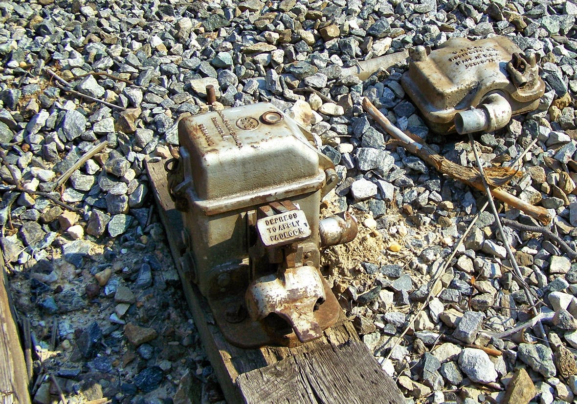
Abandoned GRS electric lock unit.
The E-Locks themselves come in two general forms, the plunger style and the pedal style. Each style is available from both vendor lines, but I want to discuss the pedal style first since it is the one paired with those TM-20 machines I just mentioned. The pedal style consists of a small box, separate from the hand throw point machine, which locks the hand throw switch arm in the desired position. The train crew's padlock holds down a small pedal. Removing the lock allowed the pedal to raise up, energizing the mechanism. In this state a small window displays either a green lamp if the switch is free to move or a red lamp if it is not. If a timer needs to be run, releasing the pedal starts it. Any timers and signaling relays are located in a trackside cabinet. When the lamp is green a second pedal can be depressed to unlatch the hand throw switch arm. Below is an example from the old CP-VO on the former Conrail Selkirk Branch where a direct control pedal type e-lock locks the throw arm of a basic dome type hand throw switch stand.
Interlocked e-lock hand throw switch stand within CP-VO.
Here we see a low profile US&S style lock device. Here we see a TM-20 with an SL-25 electric lock attached.
The SL-25 can be even located between the rails in a stand alone configuration and in this case uses a pipeline to lock two TM-20 point mechanisms on either end of an e-locked turnout.
Here we see the GRS answer to the TM-20 with an attached e-lock box. This example is located within the limits of CP-89 on the former Conrail Hudson Line and is released by a "lever" on the dispatcher's interface.
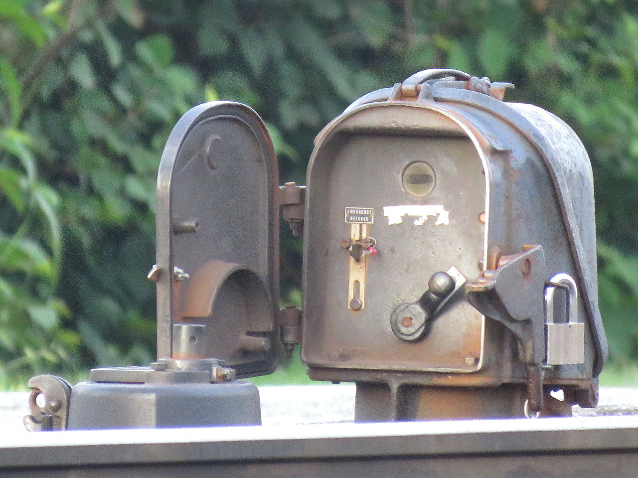
The plunger style is a bit more recognizable due to its more prominent form factor. The plunger lock consists of a little housing, sometimes on a raised pedestal, mounted adjacent to any type of hand throw switch stand. The trainman opens the little door and requests a release by moving a crank type lever from the lock to unlock-request position, similar to a US&S table interlocking machine. This engages the relays and timers in the cabinet and when conditions are safe, a solenoid releases and the crank is able to complete its travel, raising a metal plunger that is physically blocking movement of the switch point rodding in the process. The plunger is either directly below the housing or below the hollow pedestal, if present.
It is common to have both a short and long duration timer with short time (~30 seconds) applying when the main track is unoccupied and the long time (5-13min) applying when a main track train movement is possible. While short and long timers are not exclusive to the plunger type, the plunger type user interface makes them more apparent.
Another feature on the plunger type is the presence of a sealed emergency release button in case something goes wrong with the release logic. Breaking the seal and pressing the button allows for immediate release of the points. On the pedal type e-locks this functionality can be provided by an optional key switch.
Pedistal mounted plunger lock. Note the housing's similarity to a semaphore signal's.
These two types of e-locks are the bulk of what one will encounter in North America with the US&S and GRS equipment lines offering both form factors. It's actually pretty simple if you think about it, but if you don't want to take my word for it, here is a video from Mark Clay McGowan that describes the operation of each type in far more detail.
I hope you all found this interesting. I didn't get into the nitty gritty of identifying every exact model of lock, but now that you know what to look for, see if you can spot the slight differences out in the field.
For years concerns of PTC interoperability drove all manner of decision making at freight and passenger railroads. For example's CSX decision to isolate itself from SEPTA's Regional Rail network, NICTD choosing not using the cab signal codes present on its line because Metra Electric wanted to use the freight-centric ETMS and MARC dumping ACSES for reasons. However one common thread is that when push comes to shove, equipping locomotives with multiple PTC systems is not a big deal (although it certainly isn't free).
Case in point are the SD60E locomotives that are always leading certain Norfolk Southern intermodal and manifest trains traveling on its New England Bridge Route between Harrisburg and Ayer, Mass. Between Harrisburg and Sunbury its on ETMS, then its off PTC entirely all the way to Binghamton. Then it on CP's ETMS all the way to Mechanicville, NY. From there it hits the former Boston and Main which is again PTC-less, but at Wachussetts it enters MBTA territory which uses Rule 562 cab signals and ACSES the last few miles to Ayer. These SD60E's are dual equipped for PTC and ACSES and although less needed on the NEC due to Amtrak dual-installing ETMS, they found a new home on this run. If I ever get close to one I'll see if I can get a photo of the antenna.
Anyway, I heard that due to the shift of NS New Englande route internodal trains to the former Conrail Boston Line, this unique PTC situation will soon be obsolete as manifest freight might terminate at East Deerfield or something. If you're a fan of oddball leading equipment quirks, get your photos while you can.
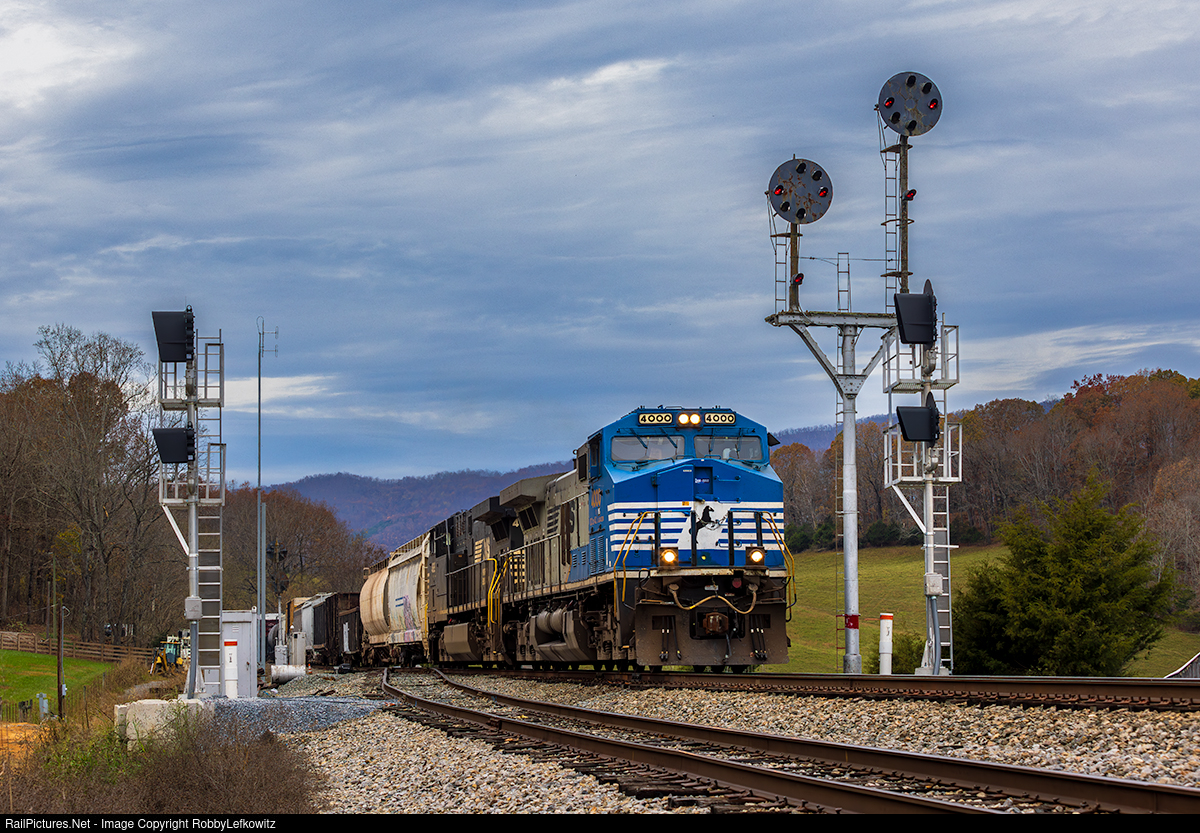
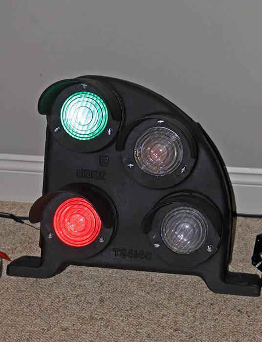
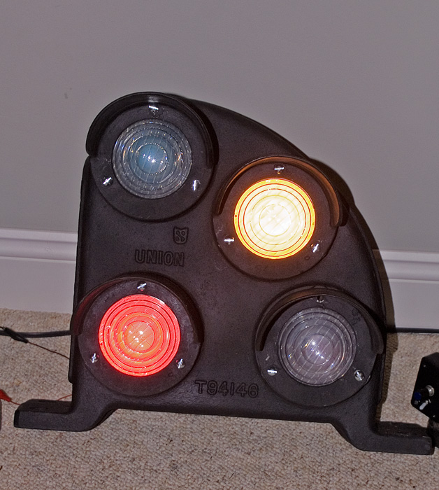
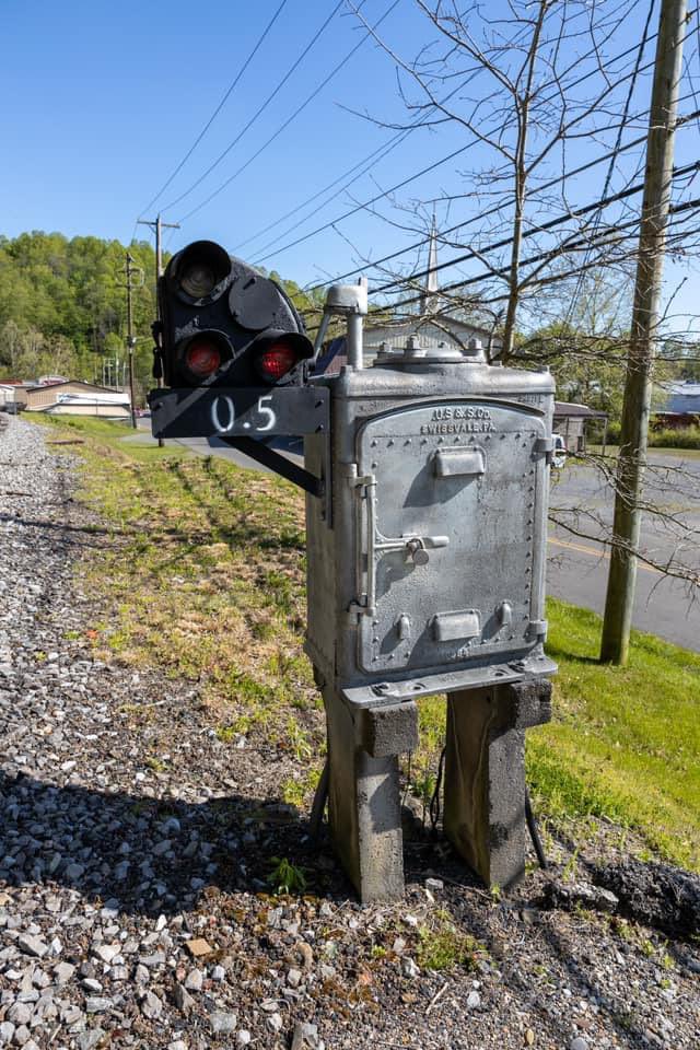
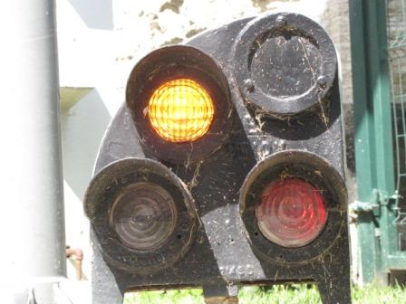
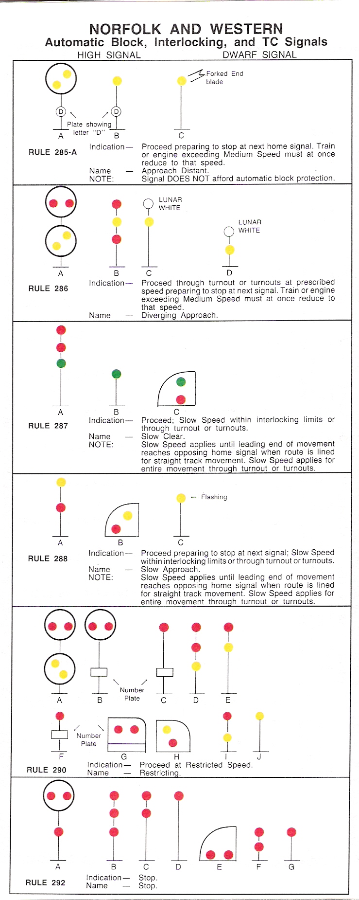
It's sometimes easy to forget that the PRR position light dwarf signal was also used by PRR ally Norfolk and Western Railway in addition to the regularly sized position lights. Their PL dwarf was even included in the 1959 N&W program to partly colorize their signals resulting in something that gave off definite UK "ground signal" vibes, albeit with the ability to display green.
Although the old N&W has been ravaged by re-signaling projects over the last decade, there are still a number of well preserved lines deep in the Appalachian coal country and Virginia. However the same cannot be said for the N&W CPL dwarf as the N&W had color light dwarf alternatives in its rulebook as early as 1961. Therefore the N&W had a multi-decade head start on replacing its PL dwarfs at the point where NS started to get involved. As of the time of this post, it has been reported that there are only 4 N&W PL dwarf signals remaining in active service at three locations. The first location is Iaeger, WV, the second Coeburn, VA and the third, with two CPL dwarfs, is Cloverdale, VA.
The Iaeger example is immediately adjacent to state route 80 just east of the Tug Fork bridge at IAEGER interlocking, just past the west end of Auville yard on the Pocahontas Division Dry Fork Branch near the village of Hull where the three track N&W position lit full crossover used to be.
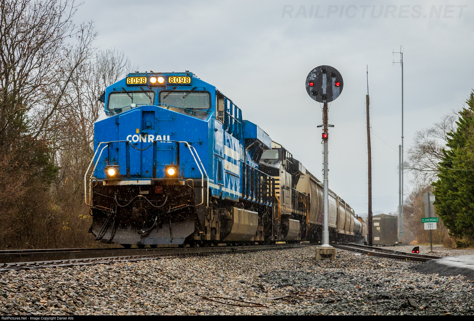
The Cloverdale pair are located at the east end of the Cloverdale Branch on the Roanoke District's CLOVERDALE interlocking about 8 miles north of the Roanoke Terminal in Roanoke, VA. The first governs the end of a long industrial track that serves a concrete plant and the second serves as the exit signal for the Cloverdale siding.
The final location is actually an automatic distant signal on the otherwise unsignaled Toms Creek Branch for COEBURN interlocking on the Pocahontas Division Clint Valley District. It is located just off Tate Ave, a few blocks from the VA state route 158 and the central business district. All three locations are in the vicinity of recent re-signaling efforts and can be considered highly endangered as a couple of other known examples, including another isolated automatic distant in North Carolina, were recently lost.
Of course rare signal types have always popped up before and I'm just reporting on the results of a forum discussion so if you are aware of an N&W CPL dwarf that has been missed please let me know in the comments! The first draft of this post actually missed the Coeburn dwarf so thank you Oakley for pointing it out.
In yet more fallout from the NS purchase of the former D&H Main Line, the re-signaling ax has hit the siding in Afton, NY after randomly bouncing around the line between Schenectady and Sunbury, PA. The real shame was that at least the north end of the siding, CPF-587, was on track to stay searchlit under CP ownership.
As of 2014 CPF-587 had two CP type GRA SA searchlight masts on the south end that replaced a D&H style searchlight bracket at some point between then and 2008.
CPF-587 also had a D&H vintage single track cantilever mast at the north end that remained untouched until the summer of 2022(!) when a Canadian Pacific in-house type searchlight mast went up.
It is unclear if this was part of a long term Canadian Pacific plan that NS management later nixed or just something NS scraped together as a temporary measure, but by fall 2023 both the out of service bracket and active cantilevers were gone with Darth Vaders and a new relay hut in place.
Although this was always to be expected and CP was in the midst of its own scattershot re-signaling of the D&H line. It is a major shame to lose one of the best preserved interlockings on the route in so short a space of time. Unfortunately the D&H route is well off the beaten path and I my best efforts have only allowed me to nibble at the ends. If you live in the I-88 corridor please do your best to get some photos at those interlockings that remain.
It has been a decade since ALTO
tower in Altoona, PA closed and after a conversation with persons
directly involved in the process I have come to learn that the
likelihood of its preservation seems increasingly remote. The good news
is that there are currently no plans to demolish the tower by Norfolk
Southern, however the previously touted move the tower in its entirety
to the Railroaders Museum about a half mile to the east are unlikely to
ever come to fruition due to the structural condition of ALTO tower itself.
Immediately
after the tower's closure there were two competing plans about how to
preserve it. The first was to move the tower in its entirety in a
similar process to the recent move of WB tower in Brunswick, MD. The
second plan was to gut the tower of all internal components, strip off
all of the architectural ornamentation and then reconstruct the tower
from scratch. One of the advocates for the second plan expressed that
his motivation to sacrifice the 1915 structure was due to it being
fatally compromised by termites and requiring asbestos remediation. All
up, full preservation and relocation of the 1915 structure would cost
multiple times construction of a duplicate fitted out with the internal
components and external ornamentation. It would also avoid the fate of
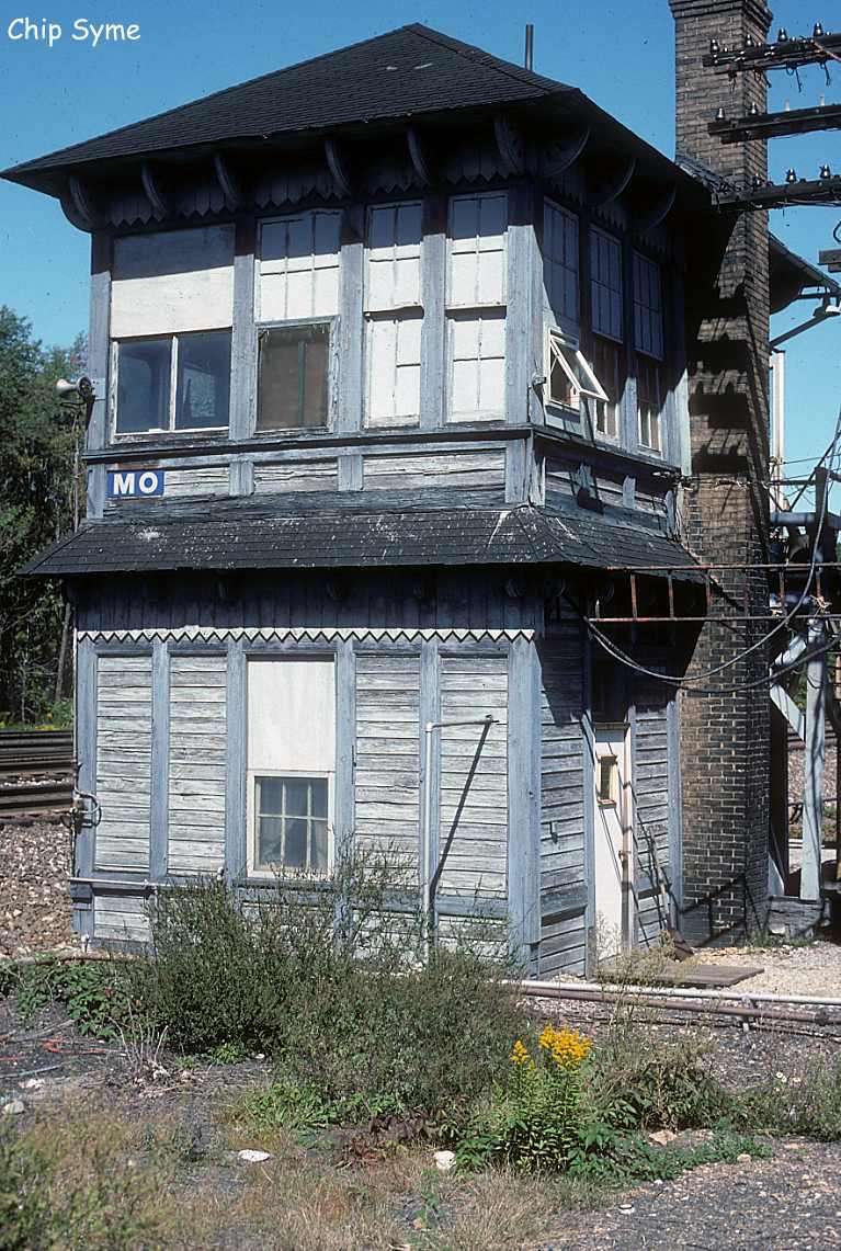
MO tower about 10 miles down the Main Line in Cresson, PA that literally
fell apart during a late 1990's effort to relocate the structure to a
nearby railfan park due to compromise of the 100 year old wooden
structure.
Nevertheless, higher-ups at the Altoona Railroadsers
Museum decided on the full preservation plan and drew up a phone book
sized document about the tower and the process (with more than a few of
my photos included I might add). At this point the sizable cost of the
preservation plan became a barrier to implementation along with whatever
roadblocks NS would be inclined to throw up. In the following decade
the tower has started to lose interior items to theft with the bank of
glass timers being an early casualty. Although it is more secure than
some of its peers, the wooden structure remains vulnerable to vandalism
and fire. BTW I attempted to gain a PDF digital copy of the preservation
document from the the individual I was speaking to, but he never
followed up after I gave him my contact information. Hopefully he will
become aware of my interest and reach out.
Let me be clear. I am not saying that ALTO
tower is doomed to demolition or fire. It is immediately adjacent to a
major roadway and could still be saved according to the 2012 plan. The
point of this report is to provide the community with an
update/explanation after the well known preservation plans seemed to go
nowhere. I don't have independent verification of the claims expressed
to me or independent analysis regarding the best course of action. The
better option is absolutely relocation of the 1915 structure, but we
should all be clear eyed about that not being possible. It's also
unfortunate that the ideal option of preserving ALTO in situ appears to have never been on the table due to NS and liability paranoia.
The typical view of Pennsylvania Railroad position light signals mounted on a steel angle iron signal bridge is one where two heads are mounted on a short pole that is in turn attached to the signal bridge structure.
But what if I were to turn this view...about its vertical axis.
Do you see it yet? How about now...
As is now obvious, the original PRR concept for mounting the then new position light signals was to place the lower head on its own little mounting mast, forward of the upper head. In the above example at the late CP-PENN, this provides all around maintainer access to the both signal heads to replace bulbs or clean the lenses, although period signal bridges would have afforded this access only to the upper head. As time went on, the more common single pole mounting became standard. Still, the earlier step-mounted position lights were left in place.
Above we can see the eastbound signals at the late CP-GRAY with an original configuration step mounted PL in the center, a modified step mounted signal with a Safetran lower head on the right and a standard mount PL on the left.This reflects the PRR Main Line 2x2 Rule 251 configuration that was later altered by Conrail to double track Rule 261.
With most of the PRR position lights now removed from Class 1 service, the best place to catch stepped position lights is on Amtrak's Northeast Corridor between Philadelphia and Wilmington. The above example are the northbound signals at HOOK interlocking in Macrus Hook, PA. The stepped signals seen below are the southbound signals at BALDWIN interlocking in Eddystone, PA.
Like the previously discussed compact position light mounting, the stepped mounting is another one of those things you might never have noticed until it was pointed out.


