A blog devoted to explaining the ins and outs of North American railroad signaling, past, present and future. This blog seeks to preserve through photo documentation the great diversity and technical ingenuity of 20th century signaling and interlocking hardware and technology. Related topics cover interlocking towers and railroad communications infrastructure.
Note, due to a web hosting failure some of the photos and links may be unavailable.
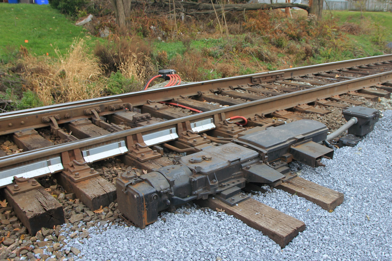
I few years ago I posted an article covering changes to the US&S logo over time as seen on its M3/M23 line of electric point machines. This article also covered off brand copies of the M3 from companies such as Patco Rail Services and Vossloh. CSX in particular had gone all in on the Vossloh "VSM-24" product.
Well it appears that CSX has found a new supplier, kinda. Apex Rail Automation appears to have taken over Vossloh's VSM-24 production line as the only thing that has changes is the stenciling and the lack of a cast company name on the circuit controller housing.
Of course the other news headline is that CSX is replacing its B&O era GRS Model 5F and 5H machines in B&O territory. Maybe Vossloh made CSX a offer they couldn't refuse and then realized they then couldn't make a profit. We'll see if Apex has any better luck.
Electrically locked switches are the red headed stepchildren of the interlocking world. Not nearly as glamorous as their powered brethren, and rarely ensconced within the safe confined of interlocking limits, electrically locked switches help make North America's efficient bi-directional main tracks possible. For the uninitiated let me clarify that while powered points are also "locked" by something involving "electricity", when I say electrically locked switch, I am referring to a hand throw switch that has some sort of electro-mechanical interlock that prevents operation in the face of an unsafe condition.. E-locked switch hardware is provided by both major North American signaling lineages (US&S and GRS) and in today's post I am going to provide a quick overview of the broad e-locked switch families and how they work.
In the beginning if a railroad didn't want the expense of interlocking a switch with signals via a staffed tower their choices were to assume the risk of trains not being able to get stopped by an improperly set hand throw switch or ensure that all hand throw switches were in the trailing configuration, something that required at least two single direction main tracks. As track circuiting became the norm, operating a hand throw switch could shunt the circuit like any other obstruction, but this wouldn't be much help if an approaching train had already passed the previous block signal.
Unprotected hand throw switch equipped with a track circuit interrupter.
The easiest solution is procedural control where the employee shunts the track circuit, waits a proscribed period of time, then throws the switch. However where the railroad desires a bit more assurance than a padlock and watch, the electric switch lock comes into play. The concept is simple, use a solenoid mechanism to prevent switch operation until allowed by the signaling system. This can include direct dispatcher/operator control, like from a lever on an interlocking machine, or conditions such as track circuit occupancy or a rundown timer. In general direct control is the less common of the two as within interlocking limits railroads tend to just pay a bit more for power operated switch machines.
US&S TM-20 switch stand without an electric lock.
At this point I want to take the time to clear up a misconception regarding electrically locked switches. Above is the US&S TM-20 hand throw switch stand. It kind of looks like a miniature point machine with wires going into it, a mechanism to work a pipeline connected derail and an extra locking bar. For years I thought this was an electrically locked point machine because it appears on main lines that tend to benefit from electrically locked points. However there is nothing in a TM-20 that provides for locking functionality. The cover on the end is just houses an integrated make/break circuit controller. So while this type of switch stand might look the part, the real e-lock is a bolt on component.
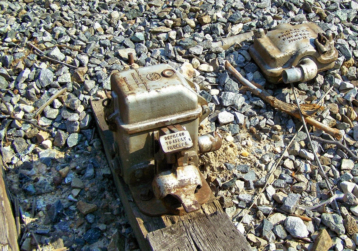
Abandoned GRS electric lock unit.
The E-Locks themselves come in two general forms, the plunger style and the pedal style. Each style is available from both vendor lines, but I want to discuss the pedal style first since it is the one paired with those TM-20 machines I just mentioned. The pedal style consists of a small box, separate from the hand throw point machine, which locks the hand throw switch arm in the desired position. The train crew's padlock holds down a small pedal. Removing the lock allowed the pedal to raise up, energizing the mechanism. In this state a small window displays either a green lamp if the switch is free to move or a red lamp if it is not. If a timer needs to be run, releasing the pedal starts it. Any timers and signaling relays are located in a trackside cabinet. When the lamp is green a second pedal can be depressed to unlatch the hand throw switch arm. Below is an example from the old CP-VO on the former Conrail Selkirk Branch where a direct control pedal type e-lock locks the throw arm of a basic dome type hand throw switch stand.
Interlocked e-lock hand throw switch stand within CP-VO.
Here we see a low profile US&S style lock device. Here we see a TM-20 with an SL-25 electric lock attached.
The SL-25 can be even located between the rails in a stand alone configuration and in this case uses a pipeline to lock two TM-20 point mechanisms on either end of an e-locked turnout.
Here we see the GRS answer to the TM-20 with an attached e-lock box. This example is located within the limits of CP-89 on the former Conrail Hudson Line and is released by a "lever" on the dispatcher's interface.
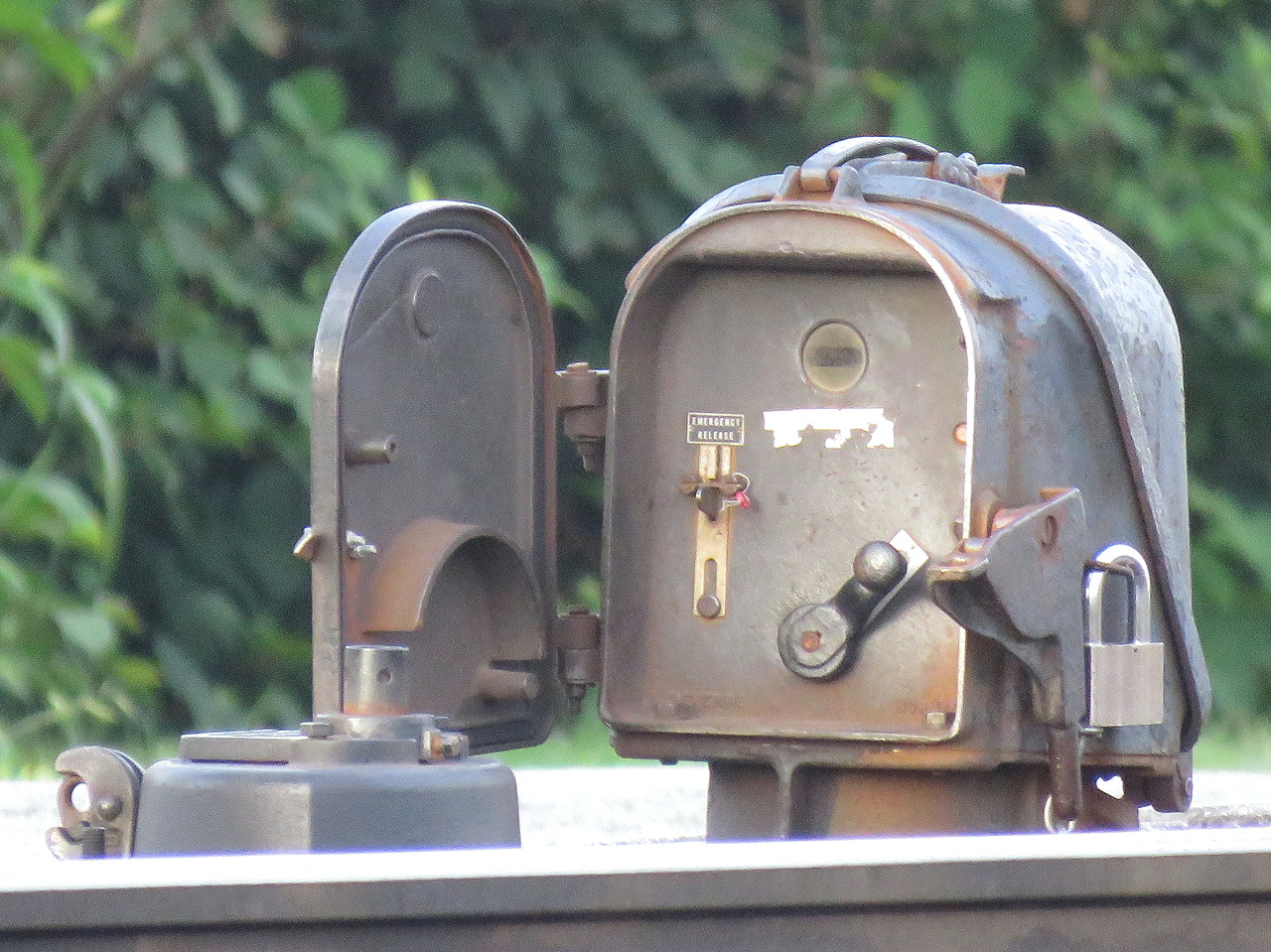
The plunger style is a bit more recognizable due to its more prominent form factor. The plunger lock consists of a little housing, sometimes on a raised pedestal, mounted adjacent to any type of hand throw switch stand. The trainman opens the little door and requests a release by moving a crank type lever from the lock to unlock-request position, similar to a US&S table interlocking machine. This engages the relays and timers in the cabinet and when conditions are safe, a solenoid releases and the crank is able to complete its travel, raising a metal plunger that is physically blocking movement of the switch point rodding in the process. The plunger is either directly below the housing or below the hollow pedestal, if present.
It is common to have both a short and long duration timer with short time (~30 seconds) applying when the main track is unoccupied and the long time (5-13min) applying when a main track train movement is possible. While short and long timers are not exclusive to the plunger type, the plunger type user interface makes them more apparent.
Another feature on the plunger type is the presence of a sealed emergency release button in case something goes wrong with the release logic. Breaking the seal and pressing the button allows for immediate release of the points. On the pedal type e-locks this functionality can be provided by an optional key switch.
Pedistal mounted plunger lock. Note the housing's similarity to a semaphore signal's.
These two types of e-locks are the bulk of what one will encounter in North America with the US&S and GRS equipment lines offering both form factors. It's actually pretty simple if you think about it, but if you don't want to take my word for it, here is a video from Mark Clay McGowan that describes the operation of each type in far more detail.
I hope you all found this interesting. I didn't get into the nitty gritty of identifying every exact model of lock, but now that you know what to look for, see if you can spot the slight differences out in the field.
The Union Switch and Signal M3 family of electric point machines set the standard for performance and reliability, however entering into the catalogue around 1953, the M3's design and technology have long since gone off patent and are free for fly by night competitors to copy. Today we will take a quick look at the US&S trademarks as applied to their M3 family as well as the marks of imitators so you can avoid getting scammed.
Before I begin I would like to state that the following is not an exhaustive list as I am sure there will be countless variations within the broad categories I will outline below. I have photos of hundreds of M3 family switch machines and I am just going to take the average and find the best examples.
First off is what I will call the small verbose branding. We have a small USS trademark followed by three lines of text consisting of "US&S Co", "Made in USA" and what appears to be parent information cast into the lid of the circuit contact portion of the switch machine. I suspect this is the earliest design as it looks most similar to the few surviving M2 machines and would likely be within the 17 year patent period starting around 1950.
The next version sees the third line dropped reducing the text to just "US&S Co" "Made in USA".
This is followed by the large logo variant that keeps the 2 lines of text, but has a larger US&S logo cast into the detector box cover.
Next we have the boxed variant that features the late model boxed US&S logo followed by "US&S Co" and "Made in USA" on earlier 1990's vintage machines and then just "US&S Co" in the later ones that are being sold up to the current day.
Now that you've seen the real stuff, let's check out some of the fakes. At the top of the skeezy list is this M23 I found on the UP Moffat Tunnel sub without any branding at all! 😬
Our next imitator is made by Vossloh and sold as the VSM-24.
Some of these are branded JMI, which is a machining and casting outfit. I am not sure if JMI was making complete switch machines and had that business bought out by Vossloh or if JMI was just a subcontractor.
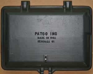
Here is one I unfortunately neglected to get a good photo of, a Patco Industries branded M23B. Patco industries is known for their rebuilding work and sells pretty much every part of an M3 for spares so I am not sure if this was built from scratch or just has a lot of Patco parts. It's worth mentioning that the branded contact case cover is made from aluminum, not cast iron.
I have heard mention of a few other companies selling M3 family switch machines and of course there are the international variants like Westinghouse Brake and Saxby Signal Company, but these are all the photo examples I have. If you know of any others please let me know in the comments and if you have some photos you wouldn't mind sharing I can add them to the list! Just remember, if you are looking for a quality electric switch machine, just look for the Union label.
The Union Switch and Signal M3 series of switch machines (including the M3, M23 and A and B models of both) is so ubiquitous and has been around for so long that one might assume the model spring fully formed from the head of George Westinghouse. However it is important to remember that the "M" is the family, not M3 and unlike General Railway Signal, where their switch machines Models 1 through 4 were radically different than the Model 5, the US&S Style M has remained fairly consistent since its introduction in 1918. In fact one of the reasons its easy to assume that the M3 (or M23) has been around far longer than its actual introduction date of 1951, is because the M22 is similar enough that both times I encountered one in the wild, I only noticed the machine was actually an M22 when I was performing unrelated photo research years later.
To review, above is an US&S M23 switch machine as previously installed on the former C&O Washington Sub near Charlottesville, VA. Below is an M22 switch machine as previously installed about 10 miles to the east in Gordonsville, VA.
I'm not going to go into all the technical details as to how they differ, there's already a page for that, but the big giveaway for an M22 vs an M23 is the non-concentric selector lever that swaps the machine between manual and power operation. The second giveaway is the bolt pattern on the top of the central gearbox with the M23 having 2 large bolts and the M2 4 smaller bolts and a more bulbous cover. Unfortunately I have yet to encounter an M2 in the wild and from the few photos online I cannot determine an easy way to differentiate it from an M3. Anyway, these and any other M22's along the former C&O Cardinal Route (now operated by the Buckingham Branch shortline) were removed in a 2013/2014 re-signaling project. However there is another M22 I just discovered situated about 5 feet from a busy public right of way.
It's this fellow, the northern end of the #1 crossover at CP-ASH in sunny downtown San Diego. In fact its directly adjacent to the Little Italy light rail station.
Although my photo is from 2015, a quick check of Google Street View shows that it is still in place as of October, 2022.
So if you happen to be in San Diego or out and around some rail line that hasn't seen a switch replacement since 1951, know how to spot an M22 and make sure you take plenty of photos if you come across one.
About seven years ago I discovered the Youtube channel of one Ian Ives, who had posted a variety of VHS era videos from inside British power signalboxes (PSB's) in the early 1990's, such as this one of Glasgow Central. Well as the way things tend to go I lost track of the channel until a recent keyword search brought it back on my radar. It turns out that Mr. Ives has had quite the exciting career as over the intervening years he posted a number of videos from Australian signalboxes. These are especially interesting due to the mix of British and American influences.
For example he has some video of the operation of a local Australian copy of the GRS pistol grip style interlocking machine, only in Australia it is paired with pneumatic point machines!
A British style lever frame at Hurstville.
A British style panel controlling a US style CTC layout at Salisbury.
A British style miniature level power frame at Sydenham.
An interlocked and manually controlled grade crossing with a modern panel interface at Parramatta Road.
And finally a modern signaling center at Wollongong.
Just like in the US, Australia has been seeing its own drive towards the elimination of manned signalboxes and non-video interfaces so most if not all of the videos capture railway infrastructure that has been now lost to time.
In addition to the tower content, Mr Ives has also posted a number of industry training materials including instructions on manual operation of every model of power point machine in service with the railway including pneumatics.
Please check out the channel as many of the above example videos came in multiple parts. New videos continue to be posted so it might be worth subscribing to.
Railroads are normally pretty tolerant of ice and slow with even the snowiest lines through the Sierra Nevada or Rocky Mountains needing the use of specialized rotary snow ploughs only about once a decade. However when rails need to move back and forth at the point of a switch, snow and ice can quickly gum things up and that is where the wonderful world of switch heating comes into play. Despite there really being only two main heating methods and a handful of fuels, the solutions employed still show a fair bit of diversity, even within the railroads themselves.
SEPTA losing a bet on the necessity of point heaters at 16TH ST Jct.
The two main methods of clearing the movable parts of switches are heating the rails directly or blowing hot air in and around them. These two categories are then divided by the type of fuel beings used to do the job. Currently the most common are electricity, gas (methane or propane) and kerosene. The decision of which point heating solution to use is typically based on the severity of the winter events any given interlocking is likely to encounter. Erring on the side of caution may result in unnecessary maintenance and capitol expenditures. On the other hand insufficient point heating capacity may not only fail in its intended role, but also succeed in making the problem worse. Railroads may further adopt the use of snow plans where the use of top quality snow melting is restricted to certain locations with the remainder being straight railed and taken out of service for the duration of the snow event.
The most basic type of point heating solution is that of the smudge pot. Named for an agricultural device designed to ward off the effects of frost, a railroad smudge pot is a long, flat metal tank holding 2-5 gallons of kerosene with a wick at one end. Placed under the running rails and ignited, the open flame will heat the rail sufficiently to ward off snow and ice accumulation within a certain vicinity.
Smudge pots can be left in place year round or deployed by maintainers in advance of a weather event. Regardless of the placement, smudge pots must by lit and extinguished manually and are generally not used anywhere a switch needs to be in service during a significant snow/ice event. They also replaced the practice of igniting oil or other flammable liquids directly on the track structure, although that can still be used to free frozen points in an emergency.
Moving up a notch in power, the electrically powered rail heater works in much the same fashion as a smudge pot, but without the need for on-site manual operation or fuel oil and with a significantly larger area of effect. The hardware device could not be simpler, usually consisting of an electric-range style heating elements strapped along the length of the outer rail.
In the above example of an electric resistance point heater in operation, the water has evaporated along the entire length of the heating element. When encountered in the nighttime the elements glow a cherry red, again similar to a household electric range.
Where heating elements on the outside rail prove insufficient, additional coils can be placed under the points themselves where the radiant heat would work to keep the mechanism clear. One major drawback to electric contact point heaters is the somewhat limited amount of BTUs available. A practically sized heating coil can only output so much heat and in extremes of temperature and precipitation and electric contact point heater will not only fail to melt the snow as it accumulates, but the snow that does melt may re-freeze between the ties and the points making mechanical clearance nearly impossible.
Electric heaters also require a fair amount of railroad and utility infrastructure. Not only do the interlocking locations need a power supply with sufficient current available to power tens of feet of heating element, they also need additional cabling between the power supply and the switches themselves and in the long run high voltage electrical cabling in wet conditions can become a maintenance issue.
When the electricity supply either isn't available or isn't enough then it's time to break out the burner bars that apply a gas flame directly to the rail. Generally impractical to use except on the outside rail, it was common to add an additional shroud to trap the heat around the rail, although these since fallen out of favor due to issues related to inspection or snagging equipment.
The propane heaters shown above generally succeed in hiding the flame and and often create a whistling noise while in operation. Some older installations that use municipal natural gas lines create more visible flames, sometimes to the alarm of passers by who think that something has gone wrong.
Excuse the click-bait-y title, but I just discovered something the other day that I wanted to bring to everybody's attention. In North America there are effectivly two families of electric point machines, The Union Switch and Signal M3 family and the General Railway Signal Model 5 Family. You can order these in a variety of variants, single control, dual control, low profile, high profile, etc. These two families have been around for so long that in the case of the M3 a variety of third parties are offering legit off-brand examples at a lower price point and without the US&S trademark. Back in the 60's, GRS decided to get ahead of the copycats by designing a brand new point machine with a new set of associated patents and trade secrets. Known as the Model 55, this cheap looking rectangle was relegated to North American transit systems, although it did kind of become the closest thing to a standard point machine that the UK has (so like I said, transit systems).
GRS Model 55 on the TTC's Scarborough Rapid Transit.
Needless to say the Model 55 was never very popular and even some of its enthusiastic early adopters, namely the Washington Area Metro and South Jersey's Port Authority Rapid Transit, eventually ultimately their Model 55's for US&S M3's. I don't know why this was the case, but I suspect a lack of support was part of the reason as GRS had a new European parent in the form of Alstom and daddy Alstom was intent on making its own new M3 "killer" along with the associated patents.
Low profile US&S M3 on the NYCTA (7) Line at Queensboro Plaza
Backtracking a few decades, to take on the GRS Model 4 and GRS Model 55's electric transit switch machines, US&S had developed a low profile version of is venerable M3 because third rail shoes are a thing on transit. Basically it looks just like a regular M3 only flattened down by an inch or two. So when the following appeared at Amtrak's rebuilt CORK interlocking in 2005, I thought they had opted for some sort of off brand low profile M3.
However something always bugged me about that shape and style and my instinct was indeed correct as that is not a low profile M3, but an Alstom GM4000A switch machine. The spiritual successor to the GRS Model 55 and, apparently to some comments I got, just as failure prone. Nevertheless a bunch of railroads bought GM4000s about 15 years ago and I happened to run into some of the survivors for the first time last December at Conrail's CP-JOHN in Morrisville, PA.
Outwardly presenting as a US&S low profile M3, the GM4000A is given away by having just two segments on top instead of three, However if you check out the manual for the original model GM4000, it does indeed have the three segments.
I'm not here to speculate about why this inferior modern replacement of tried and true 1930's technology is an inferior modern replacement of tried and true 1930's technology. That's a question for a C&S purchasing officer. What I want people to take away is the knowledge that GM4000 family point machines are a thing, how at first glance they may resemble low profile M3's and that they might soon vanish from the scene so go take some photos while you can. In this day and age every bit of diversity is a plus.
Today in North America railroads pretty much have two choices with it comes to power operated switch machines. They can get a Union Switch and Signal M3 derivative or a General Railway Signal Model 5 derivative. These aren't new models either as both designs have been around since the 1930's with only minor modifications. For the M3 family there are a few basic sub-types, dual control, low profile, that rare one that can run a movable point diamond, but unless you find yourself face-to-face with an M2, the US&S offerings are pretty uniform.
The GRS Model 5 on the other hand, comes in 8 distinct offerings labeled A through G. The first four, A, B, C and D, were available upon introduction of the family and they were eventually superseded by sub-models E, F, G and H, which are still available today. Today I am going to take you through the identifying characteristics of each model, but first some quick notes on the common design elements. All Model 5 switch machines consist of three sections. A motor sticking out of one end in a conformal casing, a drive and locking section that moves the points and locks them in place, and finally a point detection section that houses contacts and other control elements. Power only models have a flat top with a port for an emergency winding crank. Dual control models have a hump on the top with the manual throw lever on one side.
Replacement GRS Model 5A point machine at JOHN ST interlocking in Toronto.
The Models 5A and 5B were required to be operated from a GRS pistol grip style of interlocking machine as those have motor control functions built in. Power for the switch motor would be wired through the lever itself and upon the completion of throw the 5A or 5B machines would send a reverse current back to the tower that would allow the lever to be fully thrown in a process termed "dynamic indication". During the throw the operator would actually need to monitor an amp meter in case the points became stuck and the motor started to overload.
The 5A's and 5B's are easily identified by their motor housing which features an angled access door. The only difference between and A and B is that the B's are equipped for both manual and power control.
Surviving GRS 5C at CP-LAUREL
The models 5C and 5D are intended to be operated from an all-relay or other non-pistol grip style interlocking system, although they could still be attached to the latter. Unlike the 5A and 5B, these incorporate a motor controller into unit resulting in longer overall dimensions.
Surviving GRS 5C at CP-TITUS
The distinctive feature of the 5C is a large box on the end of the motor which houses a brake to slow the motor as it reaches the end of travel. The 5D is shown in the catalogue to have the same housing as the 5A/B, but I cannot confirm that layout from observations in the wild.
Uncommon GRS Model 5F at CPO-5 on the former D&H Colonie Sub.
The Models 5E and 5F are the conceptual replacements for the 5A and 5B in that these also lack an internal motor controller, but there is no requirement to have a manually operated interlocking machine. As some sort of motor control is still necessary, a 5E or 5F simply requires the control elements to be external switch machine itself.
GRS Model 5E conveniently installed as switch 5E on a SEPTA Market Frankford Line interlocking.
The 5E/F are distinguishable by their noticeably reduced length compared to the internal controller models and with the other models the 5E is power operation only and the 5F is dual control.
5F model machines seem to be popular in New England, especially on the former Guilford Rail System, and also at some former B&O interlockings that had manned towers up through the 80's or 90's.
GRS 5G at CP-TITUS
The 5G is pretty much an updated 5C without the large box for the motor brake on the end.
The built in motor controller can be seen where the cover bulges between the point detector and the drive mechanism.
GRS 5H at CP-BURN
Of course the king of the GRS model line is the 5H, which is a dual control 5G. Basically unless you want to buy a US&S style machine or you have a passenger or mass transit line that doesn't need dual control, you are going to be buying a GRS (now Alstom) Model 5H point machine. Still, while these things are about as common and appealing as Darth Vader signals, if you keep your eyes peeled, you might just spot something a bit more unique ;-)