Search This Blog

Showing posts with label electrification. Show all posts

Friday, March 8, 2024

Reading Viaduct Signaling Remains

On November 6th, 1984 the last train departed the historic Reading Terminal in center city Philadelphia 4 days after the completion of the Center City Commuter Connection tunnel that allowed through running between the former Pennsylvania and Reading electrified commuter rail systems. Immediately after crews began to rip up the tracks as the tunnel had rendered both Reading Terminal and about 2 miles of elevated main line redundant. This also marked the end of RACE STREET as an active interlocking station and its task of signaling trains in and out of the 13 track station complex from the 4-track Reading Viaduct. Built in 1930 in conjunction of the Reading's own suburban electrification project to replace the previous interlocking from the 1890's, RACE STREET, or "RA" as it was known in the days of the telegraph, would fall to the wreckers ball as the viaduct between Arch and Vine streets was turned into a mix of event space and parking to support the new Pennsylvania Convention Center, that would also employ the Terminal train shed as an event space.

The surprisingly modern RACE STREET ("RA") tower at left.

While the demise of a historic terminal interlocking tower is nothing new, even finding a photos of RACE STREET was devilishly hard due to its position two blocks from the end of the passenger platforms and often located behind stored MU equipment. At 111 levers, RACE STREET's US&S Model 14 machine was as large as the one in HARRIS, but it features only 68 working levers, the same amount as the total number of levers in CORK. In addition to fanning 4 main line tracks into 13 station tracks, it also featured a junction with the single (originally three) track "City Branch" freight line and two storage pockets on the tower side of the terminal throat. The interlocking consisted of roughly 4 parts, each delineated complimentary signals. From north to south this was the outer set of medium speed crossovers, then the City Branch junction with a 3x4 double-slip field, the trailing point double slip ladder and then the final terminal fan. The terminal area made liberal use of Restricted speed routes with no signaled routes in the fan and only a select few in the trailing ladder. Of course this is all mostly academic as everything south of the City Branch junction was demolished  What about north of the junction?


Despite the demolition of both the tower and the core of its interlocking plant, significant artifacts of race street remain in roughly the condition they were left in 1984. This is because the main line viaduct north of Vine Street was abandoned in place as an electric power right of way to reach a rail power substation. While much of the track structure was removed, the overhead lines and their supporting gantries were needed to feed the electric power and attached to those gantries were RACE STREET's 1930 vintage color light signals. In 2012 the substation was replaced, ending active use of the viaduct for rail purposes, and the viaduct became an urban exploration hot spot with plans to eventually convert it into a High Line style linear park.


Working northward, the first surviving signal bridge is on the curve immediately adjacent to the Callowhill 25hz railroad power substation and features northbound high signals 20L and 18L for tracks 4 and 2, in addition to southbound high signals 28R and 26R for tracks 1 and 3.


The southbound 28R and 26R signals featured a full upper head, a middle head with green and red lamps and a Reading style horizontal head with the yellow Restricting lamp. The reason for the middle Green lamp without an accompanying yellow is somewhat unclear but I suspect that R/Y/R Medium Approach was unavailable in favor of R/R/Y Restricting. The only non-restricting signal south of here is on track #2  so both Approach Medium and Medium Clear would be possible.


For northbound trains the 18L and 20L signals are protecting medium speed main line crossovers. Track 4 had no diverging routed and was only supplied with a R/*/Y below the 20L full speed head while the 18L had two regular medium speed routes over the #17 and #15 switches. 


Both the 18L and 20: also feature metal ID tags on the back of the upper signal head. I'll also point out that all of the color light signal hardware is US&S style TR target (tri-light) with unitized lamp housings.


The next surviving gantry hosts the southbound 16R and 14R track 2 and 4 home signals and the southbound automatic track 3 and 1 exit signals. 


The 16R and 14R are mirrors of 20L and 18L except in this case the local track gets the diverging route over the #13 switch. 


The automatic exit signals are also nothing special, although the numbering system is a bit hard to figure out and apply to further automatic that are not on the diagram. It is also important to point out that tracks 1, 2 and 4 were bi-directional with the 16L signal able to display Slow Clear for straight movements, while the 14L on track #3 could only display Restricting.


A mere 800 feet down the line was the first automatic signal location with three northbound signals on tracks 1, 2 and 4, and southbound signals on all 4 tracks. The reason for the asymmetrical signaling was due to the presence of the Reading's MU storage yards on the east side of the line at North Broad. Deadhead moves heading to and from the yard would use track #4 in the shoulder peak.


Sunday, February 18, 2024

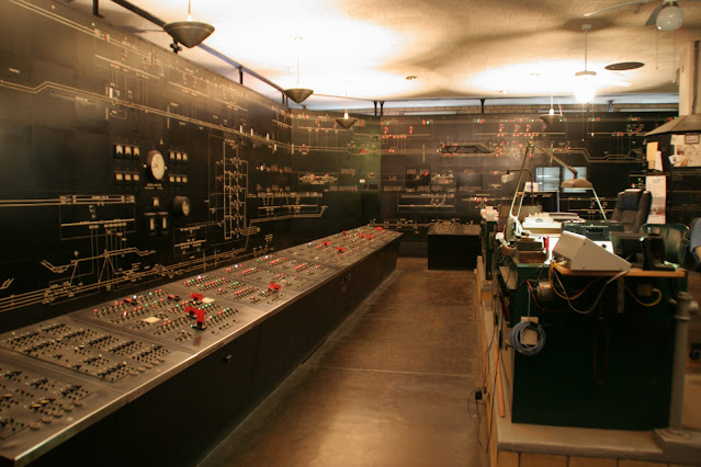
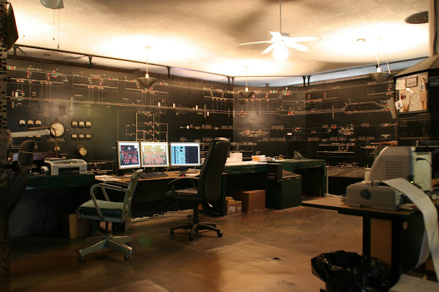
Harrisburg Power Office Gets Up and Running

Since my last update on the status of the former Pennsylvania Railroad Harrisburg Power Director's Office a surprising amount of progress has been made to get the equipment functioning in its 1943 configuration. For those of you who might not be aware, the Harrisburg Power Office used a relay based SCADA system to remote control all of the 1937-39 westward extension of the 12kv 25hz electrification network that first began operation in 1915.  The second phase of the PRR's electrification from New York to Boston had largely relied on tower operators to directly control the substation equipment via local control boards in the towers (although some substations may have been staffed 24/7 themselves). Although remote control SCADA equipment was installed in some towers and the Baltimore power office, the expansion of electrification west of Paoli, Morrisville and Perryville to Harrisburg and Enola would be under the purview of a single office in Harrisburg with a code based remote control system. 

The office was in service using most of the same equipment from 1939 through to 2013. When the Harrisburg Chapter NRHS took over the space in 2022, it was still in roughly the same condition it had been in when the doors were locked 9 years before. Known for their preservation work at HARRIS tower, including a fully functional and completely interactive Model 14 interlocking machine, the Harrisburg Chapter had its work cut out to achieve a similar level of interactivity for the Power Director's office. Based on the amount of time it took to restore HARRIS, my own personal estimate was on the better part of a decade. Therefore you can imagine my surprise when I learned that a good chunk of the active equipment had already been restored to functionality in only 18 months. In fact the video below records the moment I learned that the office relay logic had been hooked up to an Arduino mimicking the field stations.


Because the third phase of PRR electrification was financed with depression-era WPA loans, the PRR had to spread the wealth and contract half the system to Westinghouse and half the General Electric. Westinghouse and its Visicode scada system is the simpler of the two to reverse engineer and debug (one can send digits with a literal rotary phone) so currently it is the Westinghouse half of the equipment that has been wired up to modern digital logic simulating the field stations. The General Electric equipment uses a more complex protocol that requires another round of development, but that is not insurmountable. Interestingly the Westinghouse equipment was largely used on the low grade freight lines that last saw service in 1981 when Conrail discontinued its electrified operations. Therefore that equipment came back to life not after sitting idle for 10 years, but for 40 years!

The large display wall has also been restored to mostly full functionality, however compared to the SCADA consoles this functionality was somewhat limited. The indications on the display show switches being open (green) and closed (red), as well as the use of white lights to show de-energized track segments. These are wired to reflect the position of switches on the SCADA consoles or on the operator's consoles where remote operation is not in effect. Therefore the board is more of a visualization device than a real time status indicator. 

The longer term plans for the office are still under consideration. The equipment is a bit less interactive than a railroad interlocking machine with active train movements, however there are quite a few scenarios that can be played out including routine operations, breaker trips, transmission line problems and current load issues. Whatever the case may be, I'll be sure to report on it here.

Sunday, November 5, 2023

Southern Pacific Cantilever Zapped by Caltrain Electrification

In a completely predicable turn of events, the iconic Southern Pacific cantilever mast that has guarded the southern approach to the 4th and Kin St terminal in San Francisco has met its demise sometime between March and October of 2023, likely in conjunction with the erection of overhead electrification wires. It has been replaced by three LED searchlight dwarfs.

I've noticed that starting with Amtrak's New Haven to Boston electrification. recent North American electrification projects have included far more overhead clutter than those seen in Europe. Specifically the use of solid overhead beams to mount the wire brackets as opposed to cable spans. Cable spans don't tend to block signal sight lines as much, allowing existing signal placements to remain.

Anyway, I'm not sure if the 4TH ST cantilever was scrapped or donated to a museum, but as one of the last of its type in daily service, its loss is significant.

Saturday, October 8, 2022

Baltimore Power Director's Office to be "Preserved"

 More details are emerging about the fate of the Power Director's Office in Baltimore Penn Station. The entire 1911 station building is undergoing a major restoration with the upper floors slated to be turned into office space.  Unfortunately the Power Director's Office, located in room 222, is included in the redevelopment plan and will be cleared of all the PRR era 25hz railroad electrification control equipment that has remained in place since the office was closed in the mid-1980's when CTEC took over.


The less bad news is that some portion of the equipment including at least the large display board, will be relocated to a more public part of the station. A local TV newscast got a tour of the office and according to their report this new location appears to be in the 1911 building where the current ticket and baggage rooms are now. (Those facilities will be moving to a new station building across the tracks). It is unclear if all of the equipment, including 1940's based telecom gear for the SCADA functionality, will be moved or just the visually interesting conversation pieces. Also being lost is the physical character/ergonomics of the current Room 222 space and any support infrastructure like cable ducts and light fixtures.

As I previously reported, Amtrak recently leased the former Harrisburg power office to the Harrisburg Chapter NRHS for preservation and it currently shares the second floor of Harrisburg's Penn Station with a number of third party offices. Other shuttered offices still exist at 30th St station and the New York Penn Station support building.

Saturday, June 4, 2022

Harrisburg Power Dispatcher's Office to be Preserved!

 Amtrak's Harrisburg terminal complex has not one but three signaling related landmarks of great historic value.  The first is HARRIS tower, closed in 1992 and completely restored by the Harrisburg Chapter NRHS to simulated working condition, it represents the absolute pinnacle of signaling preservation.  Th second is STATE tower, closed by Amtrak in 2016, it remains preserved, but not restored or open to the public and is likely to stay that way for the foreseeable future. Finally there is the Harrisburg Power Dispatcher's office. Constructed in 1937 to manage the PRR's great westward electrification expansion, it remained in operation until 2012. Not only is the preserved hardware remarkable due to its age, but it is also one of the first wide area electric power SCADA systems ever installed

Amtrak's Harrisburg Power Dispatchers Office in 2008

While a Power Dispatching office isn't exactly Railroad Signaling, it is certainly in the same wheelhouse seeing as it was both essential to railroad operations and made use of very similar relay and electro-mechanical age technology.  The same Harrisburg Chapter team that restored HARRIS is now currently working to restore the Power Office after having obtained a 10 year lease from Amtrak.  From what I have been told, the office is pretty much as it was when the door was locked in 2012.  Everything is there, but the equipment was worn out after 80 years of operation and quite a bit of modification.


Amtrak's Harrisburg Power Dispatchers Office in 2008

This is in contrast to recent developments at the Baltimore Power Dispatchers Office that handled NEC electrification between Perryville, MD and Potomac Yard in Alexandria, VA. Located in the offices above Baltimore Penn Station, the office was gutted except for the large display board and other interface equipment. Unfortunately some very long term plans to convert the old PRR office space into a hotel have finally come to fruition and instead of preserving the space as an attraction, all remaining equipment will be sent to likely the B&O Museum where it will sit out of view or as a static display, devoid of context. 

Telecom type SCADA relay bank at Harrisburg PDO

Hopefully the Harrisburg PDO will be restored to the same level as HARRIS tower with simulated events and a fully working display and interface. If anyone thinks they have the skills necessary to help out please contact the Harrisburg Chapter NRHS.

Thursday, April 30, 2020

High Impedance

An often overlooked issue with railroad (or transit) electrification is the conflicting requirement to use the rails for traction return current and to divide the truck up into electrically isolated segments for the purposes of track circuit signaling. Installing insulated joints between substations would either cause the electric vehicle to not go or would force the return current to find other transmission paths, most of which are usually not intended to see electrical current flow and might not be too happy about it either.

The right hand rail is insulated at the track circuit block boundary, the left is not.

Your first option is to use the one rail or 1+1 system.  Here you have one rail with insulated joints creating track circuit blocks and the other rail acting as a common ground without insulated joints.  One downside is that only the insulated rail gets broken rail protection.  There are probably other downsides as well as this method was only used on some of the oldest electrified transit systems such as the NYC Subway.  Another option is to have a 4th rail system like the London Underground where traction return current uses a dedicated 4th rail instead of the running rails.  The better option is to use a device called an impedance bond to have both isolated track circuit blocks and a traction return path via the rails.


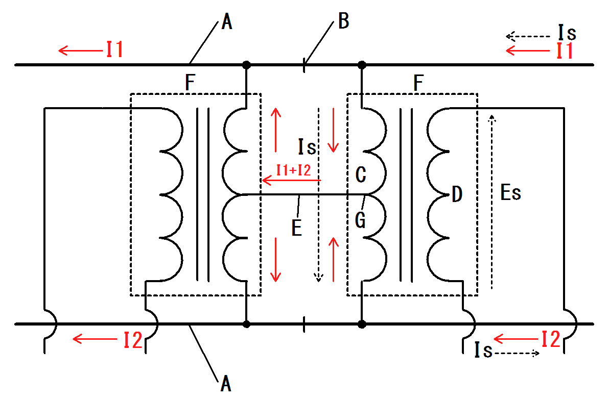
Here we see a Union Switch and Signal model impedance bond, patented in 1922.  I am not sure if there were any earlier models of bond or if this was used on the 1915-1918 PRR and New Haven 25hz electrification projects before the patent was granted, but it would have been available for the major waves of electrification that took place in the 1920's and 30's.  An impedance bond is a type of isolation transformer where traction return current can pass with low impedance (impedance is the AC version of resistance), while track circuit current faces high impedance and thus follows the path of least resistance through the track circuit logic. The necessary trick to making this work is to have track circuit current at a different frequency than the traction return current.  For example DC traction current with an AC track circuit or one frequency of AC return current with another frequency of AC track circuit. 


In the above diagram from a Japanese Wikipedia page we can see a slightly more elaborate setup for an impedance bond.  The two coils connected at the center tap are what constitute the impedance bond.  The secondary windings capture the AC track circuit current via the magic of induction and feed the signal logic.  More typically the bond omits this secondary winding and the signal logic is fed directly from the rails.  Remember this is a super high level summary so for more detailed technical information please consult Google or your reference library.


Here we see two of the 1922 patent US&S bonds and their modern Siemens replacements for use on Amtrak's NEC.  Amtrak, like the PRR before it, uses 25hz traction power and 91.66hz coded AC track circuits.  Normally the coded track circuits would operate at 100hz, but as a multiple of 25, return current harmonics could be detected as track circuit current, which is bad.  91.66hz is close enough to 100hz to be cross compatible with 100hz electronics.


The spec plate on the new bonds show the Amp rating for traction return current and the impedance values for 100hz current (400 ohms) and 60hz current (2.4 ohms).  While 25hz isn't listed I am assuming that the value would be in an acceptable range. A DC traction system sees much higher amp loads than an AC system and therefore the bonds must be much larger with thicker windings to handle it.  Systems with both AC and DC, like Penn Station, would use DC rated bonds.


 Of course the story doesn't stop there.  In the late 1960's the rail signaling industry introduced the concept of jointless track circuits for use in transit applications.  These make use of AC frequencies in the "audio" range of 1-5 kHz.  These higher frequencies attenuate after a much shorter distance and using a mix of frequencies one can have a given track circuit receiver able to hear the signal from a single specific transmitter.  Still there is the issue of the pesky traction return current that needs to move between the rails, to ground and NOT into the signaling logic.  The solution was the Wee-Zee bond (trademark of GRS) that creates this path to ground while preventing the track circuit signal passing between the two rails.


In this close up of a US&S "Minibond" on the Chicago El, we can see the the listed transmit-receive frequency pairs, the cab signal code frequency and the DC power rating (3000amps at 0.00003 ohm).


Now if you like Technology Connections, here's an interesting one for you that revolves around the necessity of impedance bonds.  Europe is currently under the thrall of axle counters for train detection as opposed to track circuits.  Why would the normally safety conscious Europe in interested in a train detection system that doesn't positively detect the presence of a train (or flood or broken rail)?  Because the Central European 16.66Hz electrification club, which includes Germany, Austria, Switzerland and a few others, electrified their rail systems were those systems were still operated using non-track circuited manual block signaling.  When upgrading to automatic block signaling, installing track circuits would require installation of impedance bonds and related electronics.  Therefore an alternative, axle counters, was sought out and adopted.

Likewise, the NYC Subway is moving to Communications Based Train Control instead of the audio frequency track circuits as their use of the one rail system would require the installation of who knows how many Wee-Zee bonds.  Just goes to show how technical decisions can be highly path dependent.  Keep that in mind the next time you have trouble figuring our the logic behind that might not make complete sense. 

Wednesday, July 26, 2017

Signal Transformers: More than Meets the Eye

In the beginning, before local power utilities were a thing, signals were powered by storage batteries placed in concrete wells at the base of the signal (or perhaps the basement of the interlocking tower).  Every so often some workers would have to come around to replace the batteries, taking the old ones to be recharged. This is why searchlights and semaphores were so popular.  Low wattage bulbs and track circuits could last for months on a charge, but it was still a labor intensive operation.  Railroads and their newfangled electric signals needed a reliable source of power and rural electric light plants that only ran from 6-9pm simple weren't going to cut it.


The solution was for railroads to become their own utilities and to string AC power lines on the pole line that was already carrying the telegraph and signal wires.  The simplest (and most popular) form of this was a 440-480v twin wire setup running on the outer position of the lowest group of wires (where it was least likely to drop into low voltage DC C&S lines).


Of course one can't just plug medium voltage AC into low voltage DC relays and expect it to work.  For this one needs a transformer and at every signal location along the line one was usually supplied on the pole to avoid bringing the 440 into the sensitive relay cabinets.  The transformers aren't very big, and its easy to not even notice they are there.  This example, on the B&O main line, likely dates from the 1950's or earlier. The 440v supply passes through two ceramic fuses so that the specific signal location can be isolated. 


On the opposite end of the spectrum, here is a modern style signal power transformer supplied by the Olsun corporation in 2003.  The AC-DC rectifiers are located in the relay cabinet or hut.  


The next level of signal power supply involved a single or three AC feed in the kilovolt range.  These were typically employed by wealthier eastern railroads with multi-track main lines and interlockings that could draw a lot of power.  Of course higher voltages required larger transformers.  Basically something on the order of what would be seen on residential utility poles.  This retired three phase example was found on the N&W H-line running north out of Roanoke.


This active example was encountered at CP-SLOPE on the former PRR main line back in 2012.  It had been installed before PCB's were banned in the 70's and has a big yellow sticker to that effect.


With transformers, frequency matters.  The higher the frequency, the lower the inductive losses and the higher the equipment one can use.  (This is why aircraft use 400hz power buses because they can use lighter transformers.)  Mains power in North America is 60hz, however the Pennsylvania Railroad employed a 100hz cab signal carrier frequency to eliminate the risk of cross talk from 60Hz mains.  This lead the PRR to actually adopt a 100Hz power supply in its electrified zone to eliminate the need for motor-generator frequency converters at every signal location.  Here we can see a retired 6.9 kv transformer on the former PRR Port Road branch.  You can see how the size compares with the 60hz transformers pictured above.


Here is a more contemporary example on Amtrak's NEC.


Today railroads are rapidly exiting from the utility business.  It's a classic case of outsourcing.  Now that public power utilities can be contracted to supply the power (even in rural locations), there is little reason for railroads to employ linemen and power engineers.  Let the power company power and the railroad rail. 

Tuesday, April 18, 2017

The Many Signals of Penn Station

In the first decade of the 20th Central, a number of transit mega-projects were under way in the United States.  Two of the most well known are Grand Central Terminal and Pennsylvania Station in New York City.  In addition to being civil engineering marvels, they also employed the latest technology in railroad signaling, which included both power operated interlocking machines and, gasp, electric signals.

I've mentioned before  how surprisingly difficult it was to create the first 100% electric railroad signals.  This was because high intensity electric bulbs (necessary to be seen under daylight conditions) of the time would have an impractically short service life and also because electric power was in vary short supply in might of the country.  However the projects of Penn Station and CGT did not suffer from these two limitations because they were underground, where it was dark all the time and they had reliable supplied of electric power on a 24/7 basis.

Right: Old GCT signal.  Left: New GCT Signal

Fast forward 100 years, while Metro-North replaced all the original 1913 signals in Grand Central, across town at Penn Station, the thrifty stewardship of Amtrak had resulted in much of the 1911 not only seeing the 21st century, but doing so just above the heads of millions of dashing commuters.  Union Switch and Signal, naturally, supplied the signaling for the entire projectfrom the interlocking machines to the relays to the signals themselves.  The signals were a custom job that, as far as I can tell, weren't used anywhere else since the electric age kicked off a rapid period of innovation that saw both searchlights and position lights entering the market in just a few years.


The Penn Station Signals consisted of a tri-light patterned upper head with G+Y+R lamps and then a lower head with an additional two R+Y lamps in a vertical orientation. Since the station trackage was all run at what is today known as "Slow" speed (15mph), there was no need for any of the more complex aspects such as Medium Clear or Approach Medium.  Two lamps were illuminated at all times to provide R/R Stop, Y/R Approach, G/R Clear and R/Y Restricting.  In the tunnels approaching the station Y/G Approach Medium and Y/Y Approach Slow indication were employed.


The Penn Station signal was a single cast iron housing with lovely rounded corners.  Due to the close clearances the signal was designed to be suspended from above, this would result in some awkward "gooseneck" mast mountings as I will show later.


From behind we can see how the signal was divided into two lamphouses, each with its own cast iron cover plate.  Note the very very old style US&S logos and markings.  Remember, all these pictures were taken in 2017, 106 years after the signals were installed.


Here we see a trio of 1911's litterally hanging out next to the now closed 'C' interlocking tower at the east end of the LIRR tracks.  The colored glass lenses are still vivid even to this day, probably because they were made with all sorts of now banned compounds.


Now if you think it is time to move on to the modern signals, you would be wrong as there is a second pattern of 1911 signal scattered about the complex.  One such example is the famous 122W "gooseneck" signal at the west end of track 7 (remember, I said they can only be suspended from above).  If you look closely you'll also notice that the G and Y lamps on the upper head are spread farther apart than on the standard Penn Station signal.


Now these "googly eyed" signals could have been some experimental or pre-production batch, but if you want a more satisfying answer I might say that this pattern was intended for ABS use in the tunnels.  The spread upper bulbs designed to simulate the offset heads of automatic signals.


Moving into the modern period we catch this Amtrak experiment with Safetran Unilens signals hanging at the east end of track 14.  Because of the problems with the Unilens that I have previously discussed, JO signal 566E appears to be an isolated incident.  So what then is the modern replacement for the unique 1911 signals?  Well actually its a modernized version of the unique 1911 signals.


Amtrak had suspended a pair of Safetran modular dwarf units below what may or may not be a Safetran lamp housing for a target style tri-light signal. The result is a nearly perfect drop in replacement for the cast iron 1911's.


Here we have an even more compact arrangement that omits the space for the "not in conformity" number plate on an absolute signal.  Hey, you can't say it doesn't work.


Here we can see how new and old compare at JO interlocking with the modern 564W signal displaying Restricting right next to the vintage 566W displaying clear.  The modern lenses are clearly larger, but both get the job done well.  In general, the former outdoor portion of A interlocking has been modernized while one is more likely to find 1911 signals scattered around JO and C, however there are many exceptions to those "rules".  Of course I'm also omitting the smattering of PRR position light dwarf signals scattered around the yard areas, but you've seen those before.

Anyway, I hope you've enjoyed this little tour of Penn Station.  Most of these photos were brought to you by the magic of modern smart phone cameras that excel at taking photos in low light conditions and also won't attract swarms of police and security officials.  Next time you are in Penn Station I urge you to look up and if you see something interesting, document it.  After all, nothing lasts forever.