Search This Blog

Showing posts with label interlocking machine. Show all posts

Saturday, November 9, 2024

PHOTOS: Amtrak CORK Tower

 A while ago I posted the first part of my coverage of the Pennsylvania Railroad's 1929 CORK interlocking tower in Lancaster, PA which covered the tower's history and the layout of the interlocking on the PRR's Main Line. Today we cover the tower itself, heading inside to see how it functioned in both its pre and post re-signaling phases. The exterior photos date from 2005 when the interlocking complex was in the process of being resignaled. 

To recap, CORK interlocking and tower were constructed as part of the 1929 Lancaster station project which moved Lancaster's busy passenger depot away from a downtown alignment with slow speeds, lots of grade crossings and partial street running. The resulting interlocking plant spanned approximately 3.3 miles of main line track, which was an outlier for early 20th century direct wire controlled interlockings in North America. Like the contemporary Lancaster station. CORK was built of a dark brick and featured a prominent bay window sheathed in copper cladding. 


The tower had one auxiliary building that housed the primary compressed air plant and was situated on the south side of the tracks in line with the extreme west ends of the high level station platforms. The tower had an internal staircase with the shelf type relay room on the first floor. With its brick construction and slate roof, the tower was in excellent physical shape as it entered the 21st century. 


Heading inside the tower we find a typical layout with the operator's desk sitting in front of the US&S Model 14 interlocking machine. A defect detector readout and overhead catenary section breaker control panel are to the operator's right with the lockers, clock and old telecom plugboard sitting to the left. One interesting feature is that the room has retained its original 1929 vintage overhead lamp fixtures. 


The operator's space is feels like a more cramped version of HARRIS tower with less space around the interlocking machine on all four sides. The gap between the scoreboard style model board and the rear aligned internal staircase is particularly small. As with other PRR Main Line towers, lever blocking devices are stored on top of the interlocking machine and the bathroom is in the left rear corner. Also note the location of the refrigerator, notice board and train order hoops. 


The sprawling CORK interlocking plant was controlled by a relatively modest 67 lever interlocking machine with 49 active levers in its 1960's configuration consisting of 23 levers for switches, 23 levers for signals, 2 levers for electric switch locks and 1 crossing lever for the Reading's Lancaster Branch diamond crossing. The plant was divided into three timer zones, A, B and C with the A timer handling the Conestoga section, the B timer the central Cork plant and the C timer the Reading crossing. The short run was 1 minute with the long run being about 5 minutes and 30 seconds. The tower also had 4 horns for Conestoga, the tower itself, Lancaster West, Dillersville yard and the Reading crossing (Longs Park).


One interesting feature was the presence of Rusty Rail tabs instead of the more usual placard. Besides that the levers were of the standard US&S crank type.


Although CORK's model board was a standard PRR illuminated type, it had several interesting features features. Grade crossing status lights were located at either end of the board to indicate the activation status of the Irishtown Road (east) or Eby Chiques (west) crossings. There were three low air alarms for East and West Conestoga in addition to the Cork main plant. In the post-1960 era two block indication lamps were added for tracks 1 and 4 eastbound. These had some interaction with PARK tower to the east as well as the intervening temporary block station at LEAMAN with track #1 being lit by the regular 2 lever and track #4 by a button on the operator's desk console. Best I can tell this was some technical method to prevent conflicting movements beyond what would be afforded by train orders and the dispatcher. Finally the most endearing model board feature was a framed photo of CORK tower itself that is also present in photos from c. 1992.
 

Sunday, October 20, 2024

A Video Guide to French "Poste d'Aiguillage"

Getting information on interlocking tower / signalboxes outside the anglosphere can be a bit difficult not only due to the language barrier, but also cultural difference about railfanning and content creation.  While I found a comprehensive site on German towers many years ago, similar resources for French signaling had yet to pop up on my radar. This is rather unfortunate as I believe that France has a strong tradition of staffed towers and electro-mechanical era power interlocking machines.It also doesn't hurt that the standard SNCF model board design gives off strong PRR vibes.

Anyway, when doing a quick Youtube search on "Poste d'Aiguillage" I found a somewhat recent public information film detailing the many styles of French interlocking machine, running the gammut from mechanical lever frames to VDU area interlockings. It even gives a shout out to a North American pattern Taylor (GRS) machine. You can watch the whole thing for yourself below.  Enjoy!


Saturday, July 13, 2024

Inside WINSLOW Tower: Then and Now

If there was a moment where I got into railroad signaling, it would be in the fall of 1998 when I quite literally got "into" railroad signaling. While being dropped off at South Jersey's Winslow Jct for the purpose of completing a 20 mile hike for a Boy Scout merit badge requirement, I noticed that one of the omnipresent plywood panels securing the lower level of WINSLOW tower had been removed. Scrambling inside I was presented with a trove of wonders that forever whet my appetite for the age of relay technology. I luckily had a 35mm film camera with me and was able to take a few photographs, but with my plan for the day already set, I only had about 10 minutes to get my fill. Although I had the motivation and opportunity to return, I as busy with school and kid stuff and by whatever time I did go back the tower had been re-secured. 

For the next two decades I would periodically check up on the tower, waiting for locals to break back in so I could follow up with more photos. It was only in 2023 that I was provided with a do over and lets just say, things were quite different. While I've covered South Jersey's WINSLOW tower and the ghostly remains of the interlocking plant on this blog before, today we will explore the interior with two groups of my own photos photos taken 25 years apart, with some additional insights provided from a 2003 urbex visit and photos from when the tower was still in service. 

If you are not familiar with WINSLOW (aka WINSLOW JCT), please check out my previous coverage to get a better idea of its history and layout. to summarize, WINSLOW was built in 1934 as part of the Pennsylvania-Reading Seashore Lines merger to PRR specifications with a brick tower, bay window and a US&S Model 14 electro-pneumatic interlocking plant. The tower was in service until 1983 when the NJDoT seashore services, run under contract by Conrail, were discontinued due to lower ridership and rapidly declining track conditions. The final service level consisted of 3 peak direction round trips to Atlantic City and 1-2 round trips to Ocean City and Cape May. When the tower closed the signals were turned and remained in place until Amtrak showed up to rebuild the line about 5 years later. 

When I first got into WINSLOW it was about a decade into its second act as a radio repeater base for NJT operations on the line. A small lattice radio mast had been build against the north side of the tower and the upper story windows were still intact and letting in light. Towers serving in useful capacities as relay huts or crew bases is one of the more common factors behind their not getting demolished. 

 
On the ground floor, the relay racks and associated relays had been removed, however the cabling that fed the US&S Model 14 interlocking machine on the operator's floor was largely still in place. From the look of it, one can see why so many old tower had their own regular maintainer that under the old system of inefficient railroad employment, could be in the position for many years.


When I visited in 1998 I don't remember much of anything in the ground floor, but in the 2003 urbex photo we can see that it was being used for general storage. I recall being informed by a Southern Railway of NJ employee mentioned that they had access to the tower, but I can't confirm if the items being stored were theirs or not.

There is a single flight of stairs along the rear wall connecting the relay room to the operator's floor. I could not tell if the relays were caged off or not as this was the typical practice to prevent operators from being tempted to tamper with the interlocking equipment to "fix" certain problems. In the 2003 photos we can see shelf style relays on the stairs, but I did not recall seeing any in 1998.


Heading up the single flight of stairs to the operator's level revealed something unexpected, a false wall built lengthwise across the room with a door in it. 


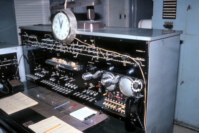
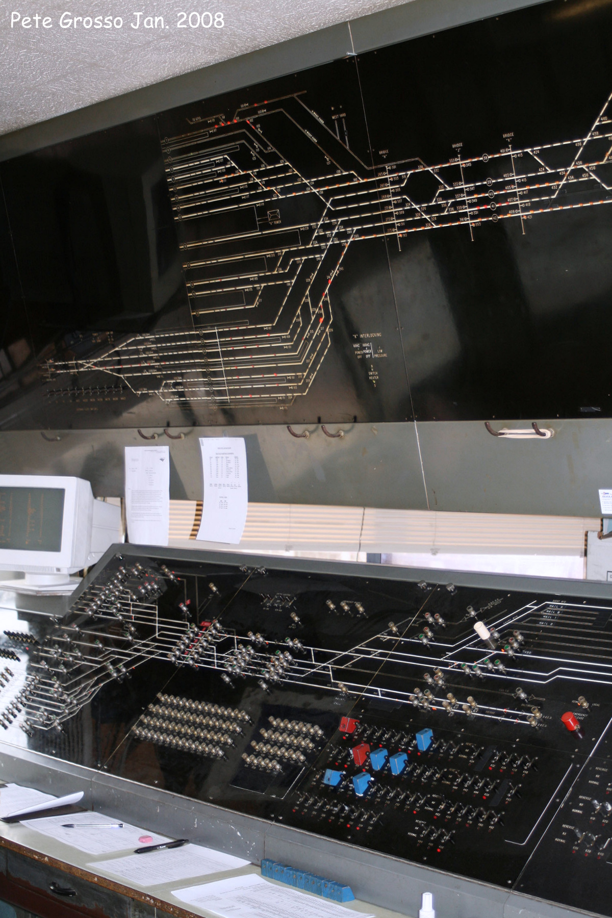
The false wall had the unfortunate effect of blocking the view of the original PRR pattern model board, expect for a small bit at the top. I also managed to get a tight angle photo in from the side that came out pretty well all things considered. 


The model board matches its final appearance from the mid-1960's through to 1983 where the main lines to Atlantic and Ocean cities were both single track manual block. 


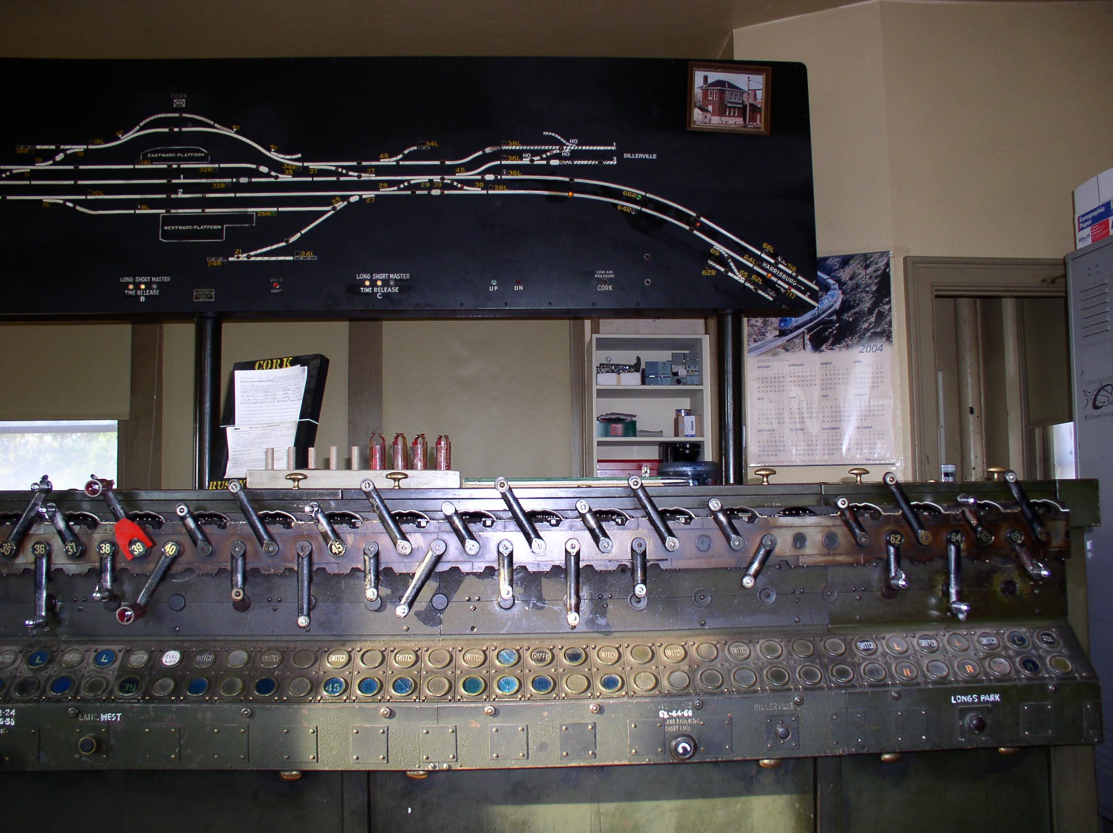
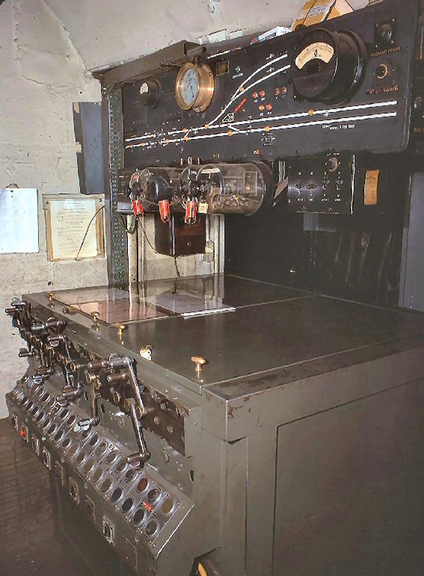
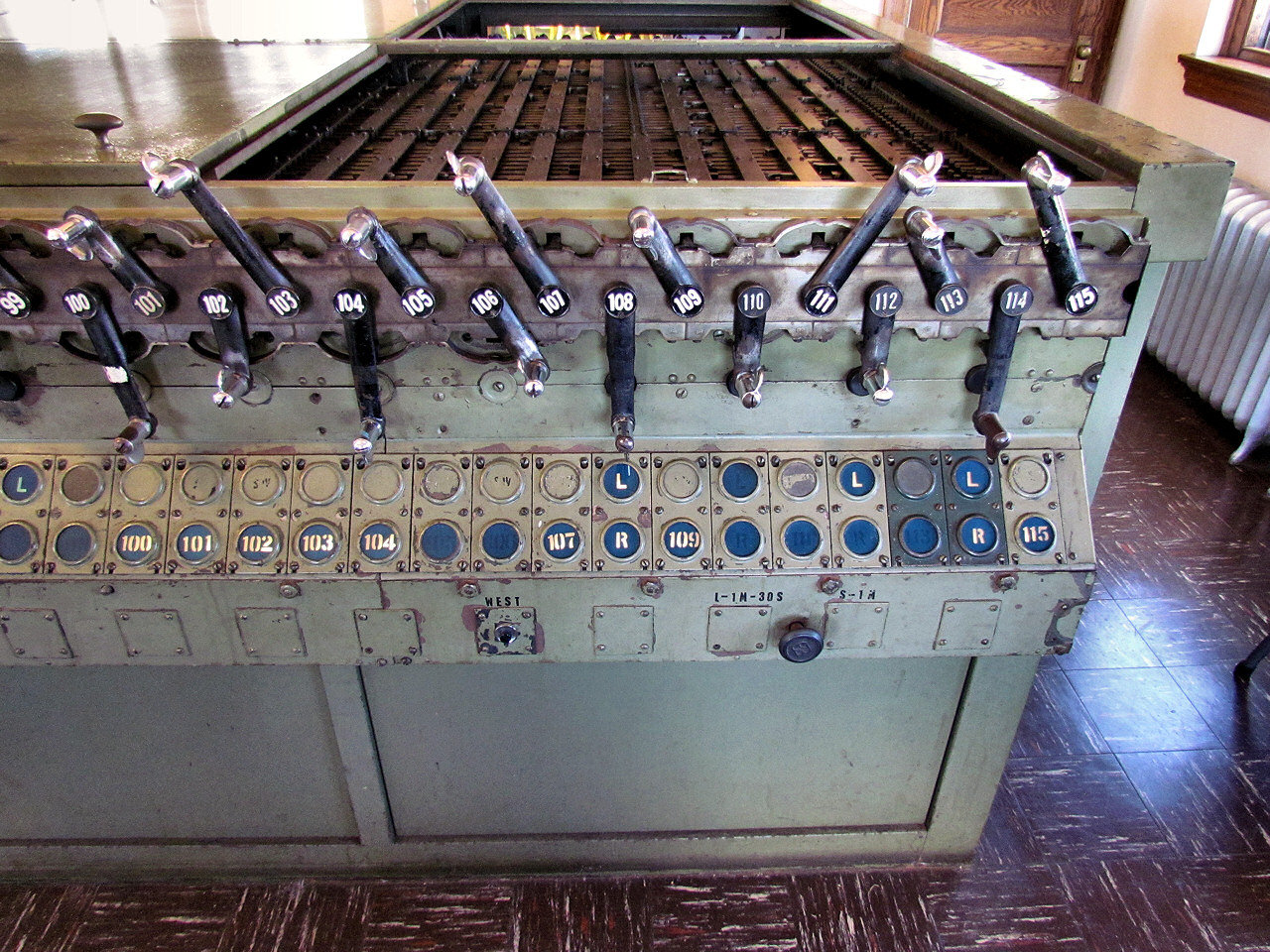
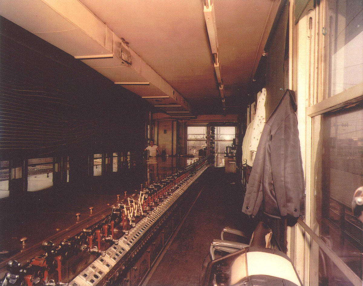
What really blew my mind back in the day was the presence of WINSLOW's 27 lever US&S Model 14 interlocking machine. Until this point I had never physically seen one or even known what one was. While some of my railroad books had contained pictures of specifically PRSL Model 14's, the fact that they didn't look like the classic armstrong type lever frame made it hard to intuit what that strange box thing in the photo was until I literally stumbled upon one and it all clicked, despite the lever cranks had all been removed.


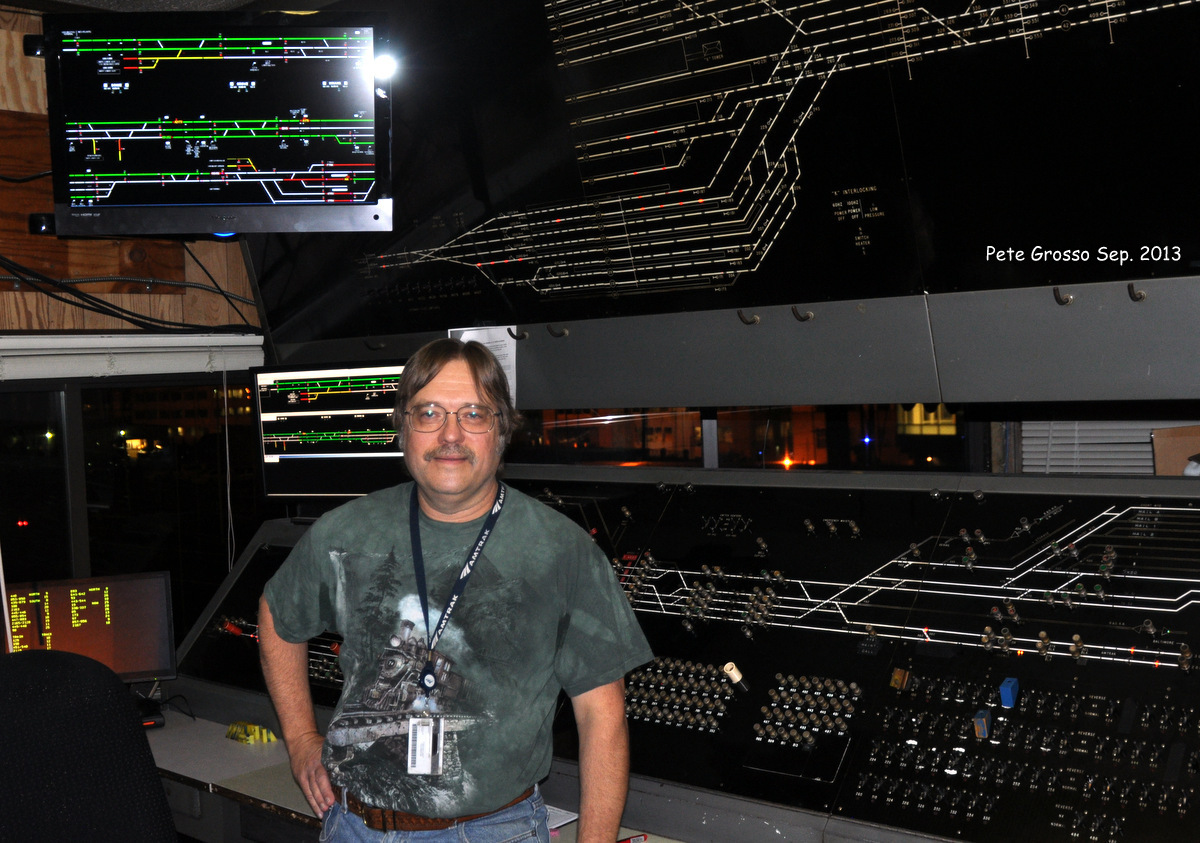
Here is the WINSLOW machine as it appeared in service. 

Friday, May 24, 2024

PU Tower Restoration Update

Former Central RR of New Jersey PU (Phillipsburg Union) tower in Phillipsburg, NJ recently held an open house to shot off the state of the tower's restoration effort. It is affiliated with the NJ Transportation Heritage Museum that, amoung other artifacts, has an operable triple expansion steam pump. I had last visited the tower in 2017 where it was clear that a lot of work had already been carried out, however the Model 14 interlocking machine was a long way from being restored due to massive stripping as you can see below.


I found some photos from the event and starting on the operator's level the Model 14 has recovered a significant amount of levers. We can also see wires indicating plans to reactivate some functionality.


The operator's desk now hosts all sorts of artifacts.


The lower level features a full suite of air compressors and the power board.


 There is also some documentation discussing how the tower was closed and reopened several times by the CNJ as is desperately tried to abandon its operations in PA. I definitely need to get up there again, but I might want to pace myself and wait until more of the Model 14 is functional, just to avoid having to make extra trips. 

Saturday, March 16, 2024

THE Source for LIRR Tower Information

The rather secretive nature of the LIRR has always made it somewhat difficult to find information about its signaling infrastructure and interlocking towers. However over the past past 26 years Steven Lynch's decidedly web 1.0 LIRR Archive on trainsarefun.com has ballooned into an absolute juggernaut of quality information. In particular the page devoted to interlocking towers covers not only the current stuff, not only the recently closed stuff, but the towers that were displaced by the modernizations of the 1950's, 60's and 70's as well as the old block stations that were displaced by automatic signaling. While the layout is a bit haphazard, you will not find all sorts of reference material that is still relevant today like photos of now out of service interlocking machines in towers such as VAN and BABYLON.


If you are unaware of this archive check it out, especially if you are doing any sort of LIRR tower writeups, like several I have planned for the future.

Saturday, January 6, 2024

1994 SUISUN BRIDGE Cabin Tour

 Movable bridge cabins are the invisible step children of the interlocking tower scene, but its easy to forget that they have all the same stuff that regular towers have including the full compliment of electro+mechanical interlocking machines. While poking around YouTube I found this video of someone's 1994 tour of the Souther Pacific's SUISUN BRIDGE movable bridge cabin. This vertical lift drawbridge is a crossing of the Carquinez Strait, which connects Suisun Bay with San Fransisco Bay and hosts Amtrak's Capitol Corridor, Coast Starlight and California Zephyr services.

As far as I am aware it is still a staffed interlocking station, although I am not sure if it retains the US&S Model 14 machine and panel seen throughout the video (specifically 10:30). In the video you can also hear the sound of a signature US&S pneumatic switch machine at 4:00 as it locks down the lift span under the control of a Model 14 lever.

Based on intro and outro clips of ABS searchlight signals on the south bank, I suspect this pre-dated the era of SP style tri-light signals that remain at the bridge today and therefore implies that the Mode 14 was replaced by a panel or VDU.

Westbound home signals SUISUN BRIDGE

The panel shown at various points in the video also lacks the VISTA crossover immediately west of the eastbound signals.

Westbound home signals VISTA interlocking with eastbound home signals SUISUN BAY

So it looks like the "Southern Pacific" style re-signaling was going on quite a bit later than I had figured what with the mid-90's Union Pacific merger.

Friday, October 14, 2022

K TOWER "Relocated" w/ N-X Panel Retired

It has been confirmed that Amtrak has relocated the train director(s) working K TOWER at Washington Union Terminal from the historic 1908 structure and into a small office in the Railway Express building adjacent to Track 29 on Union Station's lower level.


Unlike R Tower in Sunnyside yard, where a similar relocation immediately preceded demolition to make way for an Acela maintenance facility, the historical significance of Washington's K TOWER is well understood.  In 2017 I reported on plans to cover over the entire union station approach with some mixed use development with K Tower specifically singled out for conversion into some sort of high end bar. The culprit here is some combination of Amtrak's desire to simplify "management" and also cut costs along with some technical upgrades that were evidently completed behind the scenes.

As constructed in 1908, Washington Terminal was controlled by at least three US&S Electro-Pneumatic equipped towers, A Cabin, C Tower and K Tower. In the 1970's, K Tower had its long Electro-Pneumatic machine replaced with a then cutting edge N-X type interface and model board that drastically cut the need for staffing (and floor space) and centralized control of the entire terminal into a single location. This change likely took place around 1975 as the construction of the DC Metro's Red Line required the demolition of C Tower. Although cutting edge for the 1970's, by the 2010's the N-X machine was becoming increasingly difficult to maintain as parts were long out of production and failures could become rather nail biting in terms of getting the machine working again.

Although decorated with some LCD screens, the big old N-X panel's days were numbered and as soon as the control was converted into a video display interface, the human train director was no longer limited to being in the tower itself, especially if CCTV feeds could be provided. Although I suspect the historic K TOWER will be maintained and serve a railroad function, while active as a work site the HVAC, restrooms, etc would all need to be maintained to a higher standard. Plus there is the added benefit of management being able to "pop in" to "supervise". It is quite possible that the N-X panel was actually replaced years ago and COVID simply delayed the inevitable. K Tower would therefore be a rather extreme example of a "return to the office" policy. Still, given that computers can be installed anywhere, there is always the chance that the K TOWER staff could find themselves back in the old tower in the future, baring some redevelopment effort.

K TOWER joins the fate of many other pre-video "panel" type interlocking setups that I discussed previously in the content of Hoboken's rather short lived TERMINAL TOWER. Given the ease at which an N-X panel can be converted to a video interface, it is entirely possible that, rapid transit systems not withstanding, we  might see electro-mechanical machines outlast hard wired N-X panels in staffed towers.


Saturday, September 24, 2022

The Evolution of the Improved Saxby and Farmer Interlocking

In the realm of railroad interlocking machines, what does this...

Have in common with this...

Well they are kind of the same thing, the latter just being an improved version of the former that does away with most of the sweat and tears. Just like dinosaurs evolving into birds, 19th century mechanical interlocking systems evolved into smaller and lighter form factors with more and more automation until the technology reached its ultimate dead end. It might seem that a Union Switch and Signal electro-pneumatic power frame is a completely different piece of kit than the "armstrong" monsters that came before, but if we lift the hood we can see how the past influenced the future.

Setting aside who invented what and when, by the end of the 19th century there were two common mechanical interlocking styles coming out of the UK. The Style "A" Machine used a vertically oriented interlocking grid where lever bars on the Y-axis would interact with locking bars on the X-axis via a system of tappets. This style is what tends up show up in books and diagrams as it is the easiest to visually digest. The other system was the Improved Saxby and Farmer Interlocking, this used a horizontally oriented locking grid with lever bars moving in the x-axis interacting with locking bars in the z-axis via dogs. Regardless of the terminology, the key takeaway here is that there were two primary interlocking systems and Union Switch and Signal wound up with the US license for the Improved Saxby and Farmer variety.


Above is an IS&F implementation at the abandoned Buffalo, Rochester and Pittsburgh Railway tower at C&M Jct near Du Bois, PA. We can see how the lever bars are engaged by rotating shafts. The shafts were in turn attached to cranks that were in turn engaged by rockers that changed the back and forth motion of the large interlocking lever into an up and down motion that then rotated the shaft, ultimately sliding the interlocking bar back and forth in the x-axis (if the interlocking conditions allowed). In the photo below we can see how the rockers engage with the cranks behind the row of levers on an more complete lever frame.

So what does this have to do with a Model 14 machine? Well if we literally lift the hood we immediately find the exact same style of longitudinal lever bars, just slightly smaller and more compact.


Because on "power" interlocking machines tower operators no longer needed large physical levers to throw the switch points via a long length of pipe, all the complex mechanisms needed to convert the back and forth lever motion into longitudinal motion can be replaced by a miniature rotating crank. 


In case you were not yet convinced, the shafts that used to move the lever bars in the x-axis are still around to engage with the locking magnets controlled by the relay logic elsewhere in the tower.


In contrast, the other major type of North American pattern power interlocking machine, the GRS/Taylor "Pistol Grip" type, used the vertically oriented type of locking grid.


This horizontal vs vertical orientation explains why the largest Style "A" type frames were often in tall/narrow buildings, like STATELINE while the largest IS&F frames were in squat buildings such as DOLTON JCT.

STATELINE Tower Outside

STATELINE Tower Inside

DOLTON JCT Tower Outsde

DOLTON JCT Tower Inside

The US&S "Model 14" type interlocking machine was not even the final iteration of the Improved Saxby and Farmer type interlocking! That distinction belongs to the Westinghouse Brake and Saxby Signals Style V machine developed for the London Underground in the 1950's and used as late as 1967 for the all new London Victoria Line. The Style V was a Model 14 style locking bed turned on a vertical orientation with the levers being remotely actuated, typically using compressed air, allowing the interlocking to be remote controlled. I will probably give Style V's their own post at some point, but I wanted to give them a little shout-out in this context. Here we can see a Style V in action a bit after 1:31:25 in a 1960's Victoria Line construction public information film.


In its time railroad signaling was at the vanguard of high tech right along with the telephone system. With the pace of technology today, it is hard to believe that the concept of IS&F mechanical interlocking would be in use from before electric traction was invented up through the ATO equipped Victoria line. I guess it will sort of be how flavors of Z80 microprocessor will be in mainstream use, decades into the future.