Search This Blog

Showing posts with label panel. Show all posts

Saturday, November 9, 2024

PHOTOS: Amtrak CORK Tower

 A while ago I posted the first part of my coverage of the Pennsylvania Railroad's 1929 CORK interlocking tower in Lancaster, PA which covered the tower's history and the layout of the interlocking on the PRR's Main Line. Today we cover the tower itself, heading inside to see how it functioned in both its pre and post re-signaling phases. The exterior photos date from 2005 when the interlocking complex was in the process of being resignaled. 

To recap, CORK interlocking and tower were constructed as part of the 1929 Lancaster station project which moved Lancaster's busy passenger depot away from a downtown alignment with slow speeds, lots of grade crossings and partial street running. The resulting interlocking plant spanned approximately 3.3 miles of main line track, which was an outlier for early 20th century direct wire controlled interlockings in North America. Like the contemporary Lancaster station. CORK was built of a dark brick and featured a prominent bay window sheathed in copper cladding. 


The tower had one auxiliary building that housed the primary compressed air plant and was situated on the south side of the tracks in line with the extreme west ends of the high level station platforms. The tower had an internal staircase with the shelf type relay room on the first floor. With its brick construction and slate roof, the tower was in excellent physical shape as it entered the 21st century. 


Heading inside the tower we find a typical layout with the operator's desk sitting in front of the US&S Model 14 interlocking machine. A defect detector readout and overhead catenary section breaker control panel are to the operator's right with the lockers, clock and old telecom plugboard sitting to the left. One interesting feature is that the room has retained its original 1929 vintage overhead lamp fixtures. 


The operator's space is feels like a more cramped version of HARRIS tower with less space around the interlocking machine on all four sides. The gap between the scoreboard style model board and the rear aligned internal staircase is particularly small. As with other PRR Main Line towers, lever blocking devices are stored on top of the interlocking machine and the bathroom is in the left rear corner. Also note the location of the refrigerator, notice board and train order hoops. 


The sprawling CORK interlocking plant was controlled by a relatively modest 67 lever interlocking machine with 49 active levers in its 1960's configuration consisting of 23 levers for switches, 23 levers for signals, 2 levers for electric switch locks and 1 crossing lever for the Reading's Lancaster Branch diamond crossing. The plant was divided into three timer zones, A, B and C with the A timer handling the Conestoga section, the B timer the central Cork plant and the C timer the Reading crossing. The short run was 1 minute with the long run being about 5 minutes and 30 seconds. The tower also had 4 horns for Conestoga, the tower itself, Lancaster West, Dillersville yard and the Reading crossing (Longs Park).


One interesting feature was the presence of Rusty Rail tabs instead of the more usual placard. Besides that the levers were of the standard US&S crank type.


Although CORK's model board was a standard PRR illuminated type, it had several interesting features features. Grade crossing status lights were located at either end of the board to indicate the activation status of the Irishtown Road (east) or Eby Chiques (west) crossings. There were three low air alarms for East and West Conestoga in addition to the Cork main plant. In the post-1960 era two block indication lamps were added for tracks 1 and 4 eastbound. These had some interaction with PARK tower to the east as well as the intervening temporary block station at LEAMAN with track #1 being lit by the regular 2 lever and track #4 by a button on the operator's desk console. Best I can tell this was some technical method to prevent conflicting movements beyond what would be afforded by train orders and the dispatcher. Finally the most endearing model board feature was a framed photo of CORK tower itself that is also present in photos from c. 1992.
 

Sunday, July 17, 2022

NASSAU Tower - Gone But Not Forgotten

You may recall that some years ago I was sounding the alarm about the pending demolition of NASSAU tower in Mineola, Long Island. Well, New York being completely dysfunctional, the demolition to make way for the LIRR Main Line Third Track project took far longer than anticipated, eventually taking place sometime between August 2021. The demolition was just in time for the complete collapse of peak-period commuter travel in the NYC area rendering the third track capacity expansion completely unnecessary (😢). 

NASSAU interlocking, sans Tower, February 2022.

Anyway as the third track megaproject continues to creep forward, someone spotted NASSAU's late model interlocking panel dumped out back near some storage containers. It was unclear that the fate of this artifact was to be, as in museum preservation, scrapping, theft or vanishing into a railroader's basement, however it is worth checking out for any signal fans who happen to live in the area (and who might own a truck and some high visibility vests, wink wink).


Apparently this panel type interface was replaced by a VDU late in the tower's existence as plans were carried out for the transfer of operations to the Jamaica dispatching center as was done with QUEENS tower a few years ago. Thanks to multiple visits to the tower while it was in service along with some contributed interior photos I plan to post a more complete retrospecting on NASSAU tower in the near future, so stay tuned for that. 


In other news the pneumatic movable point diamond at the NASSAU flat junction has been removed. A major maintenance headache, the diamond has been replaced by a second Oyster Bay switch onto main track one, creating a bottleneck by forcing all Oyster Bay trains to platform on the westbound local platform. 


You can see the new configuration in the LIRR Main Line 3rd Track plan.

This type of 2-tracks into 1-track configuration is extremely rare as it doubles the chance of a switch failure impacting main line traffic compared with merging both branch tracks before a single main track switch. This will also end of ritual of inbound and outbound Oyster Bay train passing eachother at NASSAU to minimize impacts to Main Line service. The ideal solution would have been a two track flat junction using full turnouts and a mid-platform signal on the new eastbound track 3. That would have allow for the option to use both platforms if extended wrong running on track #1 was not available.


Friday, October 8, 2021

PHOTOS: Inside LEBANON VALLEY JCT Tower

The Reading Railroad was small in size, but rich in revenue due to its dominant positions in the anthracite coal fields of eastern Pennsylvania. As such it was able to punch far above its weight in the area of technical investment be it electrification, locomotive manufacture or signaling technology. A very early adopter of automatic signaling in the late 19th century with the Hall disc signal, when the Reading was confronted with plummeting demand for their premium coal product, their response was technical innovation to cut costs and increase competitiveness. 

Once again the Reading turned to signaling and was an early adopter of the area interlocking concept that allowed for the closure of many manned interlocking stations, even in areas of high traffic density. Covered previously in my piece on North American Panel Towers, VALLEY JCT (officially LEBANON VALLEY JCT) tower was part of this technical overhaul that still stand to this day. Since I managed to come into possession of some interior photos I figured I might as well cover it in its own article. 


The VALLEY JCT we all know today appears in the form of a squat, 1 story brick cabin adjacent to the Lebanon Valley bridge over the Schuylkill River that today carries part of the NS Harrisburg Line between Philadelphia and Harrisburg. However if you look at it from another angle, it is actually a multi-story tower facing the Reading Belt Line that passes under the Lebanon Valley Branch at that point. In fact there is no interlocking on the Lebanon Valley Branch at Valley Junction. The interlocking is actually on the Belt Line, hence the name Lebanon Valley Jct (as the Lebanon Valley Branch doesn't junction with itself). The reason for this misconception is that the operator's floor is more accessible to rail photographers.


VALLEY JCT was built in 1951, towards the end of the standalone interlocking tower era in North America. It had direct wire control of the aforementioned VALLEY JCT on the Reading Belt Line as well as the nearby Wyomissing Jct and less nearby Klapperthal Jct (CP-TITUS) , Cumru, Tuplehocken Bridge (CP-TULP) and Belt Line Jct (CP-BELT). As CTC projects went this was not exactly pioneering, but was still a good 5-10 years ahead of the curve.


It's local interlocking under direct wire control consists of a simple crossover that allows Belt Line trains to choose a ramp to the Valley Branch at Wyomissing Jct or continue on to coal country and/or Allentown via Belt Jct.


VALLEY JCT was built with a General Railway Signal Style K unit lever machine with sequential numbering starting at CP-TITUS and increasing to CP-BELT. It eventually gained an independent panel to control WALL interlocking in Lebanon, PA in 1968.


VALLEY JCT's CTC territory was in service up until the late 90's/early 2000's when a combined Conrail/Norfolk Southern re-signaling project updated CP-BELT, CP-TULP, CP-WALL and CP-WYOMISSING JCT. CP-CUMRU would be re-signaled around 2010 with CP-TITUS surviving until 2018 as it was targeted for removal and replacement instead of reconstruction. The original 1951 relay hut is still in place at CP-WYOMISSING JCT, complete with its Reading Company herald. 


Sunday, June 6, 2021

PHOTOS: Inside SEPTA's Last Towers

Over the last 20 years North America has seen the virtual extinction of "Paper Dispatching", the practice of railroad dispatchers being totally reliant on field tower operators as their eyes and ears. Operators report movements to dispatchers, dispatchers mark down train progress and inform the operators of any necessary changes. Depending on the railroad the dispatchers and operators may have more or less authority and in others the while two level hierarchy may not exist at all. Anyway, in this time period there has only been one rail system that I am aware of that went from Tower controlled to Dispatcher controlled in one fell swoop and that would be Philadelphia's commuter railroad SEPTA. 


Founded as an umbrella funding organization in the 1960's, for its first decade and a half SEPTA contracted with the legacy carriers Penn Central and Reading and later the government supported Conrail that emerged from the bankruptcies of both predecessors, to provide service on the Pennsylvania and Reading Railroad's vintage electrified suburban districts. The PRR side of the house was generally worked on the interlocking tower system with single towers controlling one or a few adjacent interlockings. The Reading on the other hand developed a taste for CTC schemes controlled by panels within existing towers. In the mid-1980's a series of events would combine to create SEPTA's unique tower culture. First, Conrail was forced to pull out of contract suburban operation in favor of direct operation by SEPTA. Second, SEPTA completed construction of the Center City Commuter Tunnel that linked the PRR and Reading networks, eliminating the stub terminals and third, SEPTA built the brand new Airport Line along with a number of "state of good repair" projects like the rebuilding of the Reading trunk line and improvements to the West Chester and Chestnut Hill West lines.

The result was that all of SEPTA's rails were controlled from 7 interlocking towers. The first two, WIND and WAYNE, were co-located within the old Reading WAYNE tower building at Wayne Jct and consisted of two 1960's vintage CTC panels that not only controlled practically all of the Reading suburban network, but also parts of Conrail freight lines due to the shared Reading System heritage. The next two, BROAD and MARK, were built as part of the Commuter Tunnel Project and replaced two large Model 14 legacy terminal plants with modern N-X panels. The next two, MEDIA and CHESTNUT HILL (WEST), were direct PRR legacy towers that controlled terminal operations on the West Chester and Chestnut Hill West lines with their original interlocking equipment. Finally A TOWER was constructed new in 1985 to control the Airport Line with a contemporary unit level panel.


Beginning our tour at Wayne Junction, WAYNE tower was the most traditional of SEPTA's diverse rail control locations being located inside the former Reading WS tower, a 1920's era Model 14 powered facility that controlled the double junction between the New York/Bethlehem main line, Chestnut Hill East branch and Tabor Branch freight link. Unlike the PRR, the Reading wasn't afraid of new technology and in 1965 it implemented a wide-scale CTC project that consolidated control of its Suburban network inside WS/WAYNE tower. (Note, by CTC I mean remote interlocking control as there was only a limited amount of actual Rule 261/CTC operation in this territory.) In the tower the old Model 14 machine was supplanted by two high end General Railway Signal NX panels installed in adjacent corners of the operator's floor.

Operator lines a route at 16TH ST JCT on the WAYNE panel in 1991.

Other half of the WAYNE panel in 1991.

This gave rise to WAYNE Towers's unique "Two Towers in One" layout with the "WAYNE" panel and operator controlling everything between 16TH ST JUNCTION at the top of the Viaduct to TABOR JCT (Fern Rock) on the Main Line and the Fox Chase branch (via Newtown Jct and Cheltenham Jct). The WAYNE panel saw one major alteration with the "south" end of the panel being extended to accommodate the insertion of the new HUNT interlocking and reconfiguration of WAYNE interlocking to support the mid-80's opening of Robert's Yard. Compare the above and below photos to the original 1965 configuration (NSFW).


South end of the WAYNE panel in 1994

North end of the WAYNE panel in 1994

The second panel and its operator was known as WIND and was interesting for not only being a virtual tower located about 6 feet away from the WAYNE panel, but also not actually controlling an interlocking named WIND. WIND's territory was everything north of Tabor Junction including the R5 route from Jenkintown to Doylestown, the R2 to Warminster, the old New York Branch/R3 to Woodbourne and even the previously signaled Stony Creek Branch to Norristown. WIND also had control of the New York Short Line that would become the Conrail Trenton Line north of Cheltenham Jct which included a single controlled siding and various joint interlockings between Neshaminy Jct and Woodbourne. 

WIND panel 1991 with WOOD interlocking and Fairless Branch.

Between 1991 and 1993 the first state of the Conrail SEPTAration began with a re-signaling and track re-alignment project on the Trenton Line transferring control of Conrail trains between CP-CHELTENHAM JCT and CP-WOOD (exclusive) to the Conrail dispatcher. You can see in the following 1994 photo of WIND how the north end of the old New York Branch has been deleted off the panel as an active element. 

WIND panel in 1994 w/ WOOD interlocking etc blanked out.

SEPTA's WIND would retain control of both CP-WOOD and gain control of CP-TRENT after TRENT tower's closure in 1994. Unfortunately my photos do not reveal the method of control, but it would most likely be a computer terminal seeing as how CP-WOOD and CP-TRENT was re-signaled to 90's Conrail standards. The only remaining portion of the Reading Suburban network I have yet to cover is the Norristown terminal area that was originally controlled from a CTC panel in NORRIS tower. NORRIS tower closed some time after 1988 and by 1994 the CTC panel had appeared in WAYNE tower (likely under purview of the WAYNE operator). A 1991 photo shows a non-operable mimic board installed in the tower which may have operated to inform the WAYNE operator of R6 terminal movements before NORRIS closed. 

1991 Norristown area minic board.


1994 Norristown area CTC panel.

If you were wondering how two operators could handle all the train movements on the Reading side of the SEPTA network on an NX panel without any form of automated train labeling, I was told that at peak times each "tower' each would support at least two panel operators working in a non-socially distanced manner. Based on the recollections of a visitor, it was also likely that the physical WAYNE tower operation included a train director to call some routes and handle communications with the SEPTA dispatchers. By the turn of the 21st century SEPTA WIND and WAYNE had a very distinct presence on the scanner scene with their VHF transmissions registering loud and clear at least 10 miles distant in South Jersey. It was a truly modern rail dispatching operation in all but name.

MARK tower panel.

Looping through Center City, the next tower encountered on the SEPTA trunk was MARK. Part of the Market East station complex, I believe it was located somewhere around the ticket counter / station master's office on the east end. MARK arguably replaced the 111 lever Model 14 RACE ST interlocking plant that controlled the Reading Terminal complex. The Center City Commuter Tunnel shows the gross inefficiency of stub terminals as a the 13 track Reading Terminal complex was able to be replaced by 4 through tracks. MARK "tower" consisted of a US&S unit lever panel in an office controlling VINE, a 4-track full crossover hear the north end of the tunnel, and MARK, an interlocking without any appliances (aka switches, derails, etc) that spanned the length of the Market East station platforms. It did not control the adjacent JUNIPER interlocking located between Market East and Suburban station on tracks 2 and 3. MARK opened in 1984 with the closure of Reading Terminal.

BROAD tower center panel with 20TH ST and SCHUYLKILL interlockings.

Tuesday, April 25, 2017

Swindon Power Signalbox Restoration

Hopefully most of you are familiar with the excellent job the crew at HARRIS tower has done reactivating its US&S Model 14 interlocking machine with the help of a lot of PLC's and Train Dispatcher 3.  Well over in the UK a project is afoot  to do the same thing to the old NX panel from the Swindon Power Signal Box.  The "PSB's" were a generation of British area signaling control centers that replaced the most hard pressed mechanical tower in the 1960's and 70's.  They used a lot of relay logic to implement push button N-X operation and many eventually came to feature integrated train description.  A tour of Swindon PSB can be seen below.


Swindon, like many other PSB's, are being removed from service because many of the telecon grade relays that drive the user interface and other ancillary logic are becoming nearly impossible to maintain.  Here below is a video showing the "domino" style panel board being re-assembled after it arrived at its preservation site.


Here is a brief demo of the old panel UI hooked up to some modern electronics.  And yes that is indeed the Danny Scroggins who is so well known for his comprehensive documentation of vintage British signaling and signalboxes.


Of course there is an entire Youtube Channel devoted to the project, with videos like this one showing the progress of the custom PLC components.


In fact the panel has its own preservation society and as of now they are projecting an grand opening date of June, 2018, plenty of time to score that cheap transatlantic airfare.

Wednesday, December 30, 2015

British Power Signal Box Video Tours

On a British signaling forum I frequent, a signaler known as Ian Ives uploaded a number of VHS video tours he made of some London area British Power Signal Boxes (also called Panel Signal Box or PSB) back in the 1990's.  For those of you who don't know, a PSB is roughly equivalent to the type of interlocking tower that was largely passed over in North America in the evolution from single interlocking towers to dispatch offices. They are basically what the NYC Subway calls Master Towers.

Popular in the UK between the 1960's and the 1980's, they replaced most of the electro-mechanical interlocking towers in busy urban areas as well as scores of pure mechanical towers.  PBS's contained large NX style model boards with light green tiles.  Their most high tech feature was automatic train description using small LED or CRT display boxes, which in the 1960's was quite a feat indeed.   While well documented pictorially, there are relatively few video records of how these panels were worked so check out these great resources.

If you like these, make sure you visit and/or subscribe to Ian's channel here.  If you would like an official tutorial on how these panels worked, you can find it here.


Wednesday, December 24, 2014

PHOTOS: Amtrak LAKE ST Tower

It's been a while, but it is finally time to conclude my METRA Tower series by looking at a tower that wasn't METRA's at all, but played a large role in METRA operations.  This would be Amtrak's LAKE ST tower, situated (until recently) at the north end of Chicago's Union Station.  The tower was built by the same PRR/MILW/CBQ consortium that built the entire Chicago Union Station complex in the mid-1920's.  Despite its prominence I have not yet been able to locate any period interlocking diagrams or other information that could better inform my talk, but since when has that stopped me before ;-)


Built during the roaring 20's, LAKE ST exhibited all the opulence of the era with a tile roof, copper gutters and all brick construction.  During the Amtrak era is was actually upgraded with modern picture windows and ample exterior lighting.  LAKE ST was closed in 2005 after 80 years of service and then demolished in 2013 due to an overbuild project to cover the tracks with either condos or a park. Until then it was a fixture of the north side railfan scene, viewable from the adjacent Lake Street bridge and easy to work into all sorts of photo angles. This may seem like the typical story of a classic big city tower, but LAKE ST was something special and one tip off is the windows.

Like many Chicago area towers, LAKE ST was equipped with an emergency exit.
The south side of Chicago Union Station is far more complex and sees far more traffic.  With road bridges providing an unobstructed view of the action it is what people think of when they think about long distance passenger rail in Chicago.  That part of Chicago Union Station was controlled by HARRISON ST tower, an elevated affair that was eventually surrounded by the new post office building in the mid-1990s.  At the time Amtrak also embarked on a large scale re-signaling project on the south side replacing the old Model 14 machine in Harrison Street with modern relay logic and the PRR position light signals with B&O style CPL dwarfs and high color lights.

What main people failed to realize was that the north side interlocking controlled by LAKE ST was left completely untouched and moreover, control of the south side plant was moved to a large NX panel in LAKE ST tower.  Thus LAKE ST wasn't just a tower, but was the control facility for the entire Chicago Union Station complex. Thus, nice new lighting and big picture windows.


 In 2005 time finally caught up with LAKE ST as a $45 million, 2-year project to re-signal the north end finally came to fruition.  This saw the replacement of the PRR PL dwarfs with LED searchlights, the implementation of a new CANAL ST interlocking to replace what had been a number of hand throw crossovers north of LAKE ST interlocking proper and the consolidation of all Chicago signaling control into the CUS office complex.  This included the closure of Amtrak's 21ST interlocking at the southern gateway to the CUS complex as well.  The interior photos I have of LAKE ST were taken just before and then a few years after its closure.


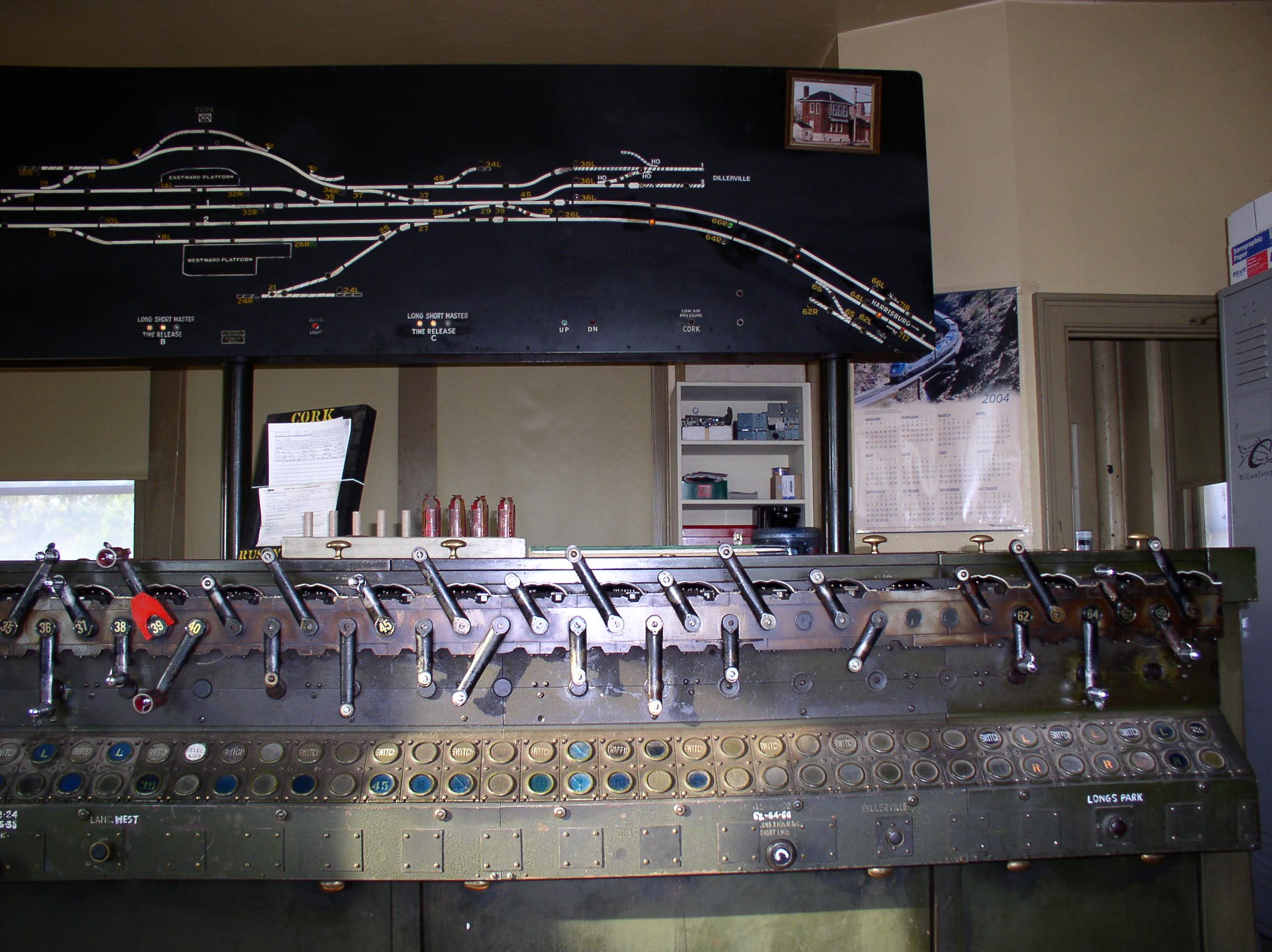
Here we see a post closure photo the 95-lever US&S Model 14 interlocking machine originally installed in 1925.  The large number of white painted spare" levers is due to the rolling closure where successive parts of the interlocking plans were cut into the new vital logic.  At the time of its closure the LAKE ST Model 14 was down to 9 signal levers, 4 switch levers and one traffic lever.


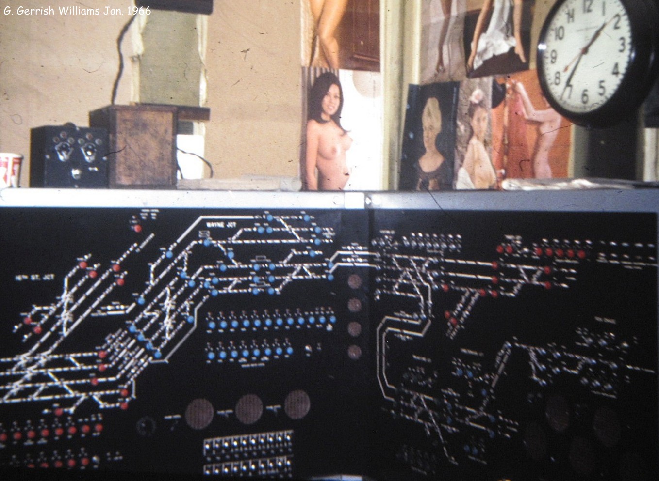
The model board shows the layout as it originally was with 11 station tracks that fanned out from a three track main line.  9 of the tracks are stub end with 2 additional through station tracks and 1 bypass track.  Station tracks are given odd numbers as even numbered tracks are on the south side of the station.  The model board is 4-colored in accordance with Milwaukee Road practice and uses green lamps for track occupancy.  Displayed signals are not shown on the model board.  Alterations have been made with a combination of black tape and hand painted lines.  On the through tracks a number of signals that are controlled from the NX panel are indicated with the N/S suffix opposed to L/R.  A quick count indicates 7 doubleslip switches, 11 single turnouts and 5 crossovers.


 In this opposite view of the model board we can see the entrance to the interlocking at the grade crossing with Canal St.  Most of LAKE ST interlocking is located underground a block or two north of the tower itself.  The tower only had direct sight of a few hand throw crossovers near Canal St and the outer crossovers between Lake St and Randolph St.  One of the reasons for the rolling cutover was because the interlocking was not only resignaled, but also reconfigured.  Compare the model board above with a facing point ladder track, stub end track 5 and a non-circuited track passing close to the tower to the current layout below.


Here we see a parallel trailing point ladders, one of which employs a doubleslip, the other a scissors crossover between the two center tracks.  The non-circuited track has been removed leaving the single station bypass track.For a more complete view of the current interlocking layout please refer to this computerized model board of the Chicago Union Station area. 


Back inside the tower we see an odd blank patch on the interlocking machine where lever spaces 1 through 32  had been removed.  This does not appear to have been part of the re-signaling effort given the age and condition of the metal.  Looking at the model board I suspect there was some spare capacity at the lower end of the machine in addition to some of the northern part of the plant being made redundant through hand operated switches. Without lever positions on the frame I am unsure how the 16L, 18L, 20L, 24R, 26R and 28R holdout signals at Canal street were controlled.

 Closeup view of the levers looking down the frame towards the emergency exit door.  The bay window is to the left of the photo.  Last active lever is 94, but the frame has space for 95.


Another view of the levers this time showing the mix of 1920's and modern track lighting fixtures. 


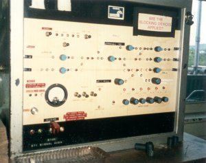
Moving back in time to 2004 we see the tower towards the end of the re-signaling project.  The Model 14 machine is still in service, but most functions have been transferred to a pair of NX panels sitting over the blank section of the frame. The remaining part of the interlocking still controlled by the Model 14 is covered over on the panels.