A while ago I posted the first part of my coverage of the Pennsylvania Railroad's 1929 CORK interlocking tower in Lancaster, PA which covered the tower's history and the layout of the interlocking on the PRR's Main Line. Today we cover the tower itself, heading inside to see how it functioned in both its pre and post re-signaling phases. The exterior photos date from 2005 when the interlocking complex was in the process of being resignaled.
To recap, CORK interlocking and tower were constructed as part of the 1929 Lancaster station project which moved Lancaster's busy passenger depot away from a downtown alignment with slow speeds, lots of grade crossings and partial street running. The resulting interlocking plant spanned approximately 3.3 miles of main line track, which was an outlier for early 20th century direct wire controlled interlockings in North America. Like the contemporary Lancaster station. CORK was built of a dark brick and featured a prominent bay window sheathed in copper cladding.
The tower had one auxiliary building that housed the primary compressed air plant and was situated on the south side of the tracks in line with the extreme west ends of the high level station platforms. The tower had an internal staircase with the shelf type relay room on the first floor. With its brick construction and slate roof, the tower was in excellent physical shape as it entered the 21st century.

Heading inside the tower we find a typical layout with the operator's desk sitting in front of the US&S Model 14 interlocking machine. A defect detector readout and overhead catenary section breaker control panel are to the operator's right with the lockers, clock and old telecom plugboard sitting to the left. One interesting feature is that the room has retained its original 1929 vintage overhead lamp fixtures.
The operator's space is feels like a more cramped version of HARRIS tower with less space around the interlocking machine on all four sides. The gap between the scoreboard style model board and the rear aligned internal staircase is particularly small. As with other PRR Main Line towers, lever blocking devices are stored on top of the interlocking machine and the bathroom is in the left rear corner. Also note the location of the refrigerator, notice board and train order hoops.


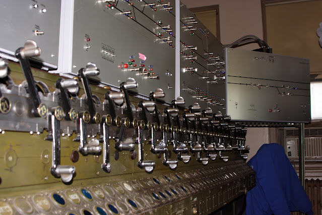
The sprawling CORK interlocking plant was controlled by a relatively modest 67 lever interlocking machine with 49 active levers
in its 1960's configuration consisting of 23 levers for switches, 23 levers for signals, 2 levers for electric switch locks and 1 crossing lever for the Reading's Lancaster Branch diamond crossing. The plant was divided into three timer zones, A, B and C with the A timer handling the Conestoga section, the B timer the central Cork plant and the C timer the Reading crossing. The short run was 1 minute with the long run being about 5 minutes and 30 seconds. The tower also had 4 horns for Conestoga, the tower itself, Lancaster West, Dillersville yard and the Reading crossing (Longs Park).
One interesting feature was the presence of Rusty Rail tabs instead of the more usual placard. Besides that the levers were of the standard US&S crank type.

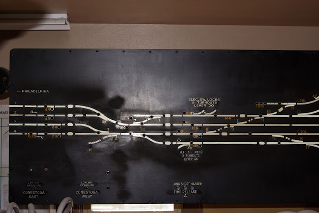
Although CORK's model board was a standard PRR illuminated type, it had several interesting features features. Grade crossing status lights were located at either end of the board to indicate the activation status of the Irishtown Road (east) or Eby Chiques (west) crossings. There were three low air alarms for East and West Conestoga in addition to the Cork main plant. In the post-1960 era
two block indication lamps were added for tracks 1 and 4 eastbound. These had some interaction with PARK tower to the east as well as the intervening temporary block station at LEAMAN with track #1 being lit by the regular 2 lever and track #4 by a button on the operator's desk console. Best I can tell this was some technical method to prevent conflicting movements beyond what would be afforded by train orders and the dispatcher. Finally the most endearing model board feature was a framed photo of CORK tower itself that is also present in photos from c. 1992.

Note on the photo below that the 66R signal is displayed for a reverse direction movement on track #1 westbound.
Before we get off the model board note this utilitarian gem of a work light and cable reel on the far left side.

In what is perhaps the single most interesting signaling related photo I have, here we see CORK's panel blocking device indicating both a blocked track #2 westward and an authorized reverse direction movement on track #1 westward. At the time Amtrak was performing a significant tie and rail replacement project necessitating long term single tracking and this photo, along with the above model board photo with the displayed 66R signal, captures this uncommon procedure. Panel blocking devices were an extra cost, labor saving device used by the PRR and few others. Instead of operators having to apply (and track) blocking devices to individual levers, they could use a panel blocking device to automatically block out entire routes regardless of the switches and signals employed. Moreover the panel blocker would be default block reverse direction movements unless explicitly allowed. Here we see both blocking knobs for the westward Main Line operated for a reverse direction move.

Here we see the panel blocking device with only the track #2 hold in place.
Here we have the tower readout for the hotbox detectors at track #1 milepost 61.4 (westbound) and track #4 milepost 73.6 (eastbound). The detectors were made by the Servo Corporation of America with Harmon providing the electronics for the remote link. The analog tower readout uses scrolling graph paper with an ink needle that graphs the magnitude of each axle's temperature. If a a dragging equipment detector is provided the system makes a single extra mark. From the positions of the marks we can see Amtrak is still running 3-car Keystone Service trains and the locomotive axle bearings are hotter than the coaches.


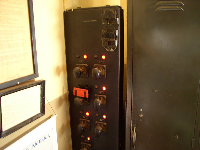
Next up is the local control board for overhead catenary section switches. While most of the electrification system was controlled by an early generation SCADA system in Harrisburg, the staffed towers would still maintain local control over section switches. I am not sure if control was shared with the power director or if these were for the 11kv breakers or just the more basic switchgear. Similar local control boards were in STATE and THORN towers.
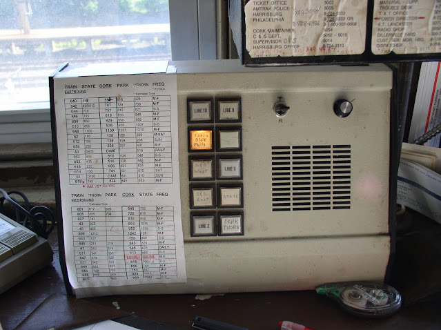
The block phone was of a squawk box style with lines to PARK/THORN eastward, STATE westward, lineside party line call boxes both east and westward and finally the dispatcher.
Mounted on the old telecom plugboard were two low arm alarms. Although they look like air gauges, the dials are set to the typical point of low air warming, 80psi and 55psi. At 80psi all points must be set normal and not touched without authorization. At 55psi no switch can be operated.
All the Main Line towers have these legacy switchboards. I don't know how they worked or exactly what they were for, but CORK's example is in particularly good shape with many of the patch cables intact.
No tower is complete without a 1950's General Electric wall clock.
The restroom had a mix of both old and new elements.
In 2007 CORK tower was re-signaled and its territory split into 4 independent modern interlocking stations, HOLLAND, CONESTOGA, CORK and LITITZ. However CORK tower was not closed. Instead the Model 14 was replaced by a series of unit lever panels stacked on top of the old interlocking machine. The panel for the new LEAMAN interlocking was also installed along with one for the replacement PARK interlocking, although I do not believe it was ever activated. Here the operator would work until control of the territory was passed to the Section C/B dispatcher in Wilmington.
The PARK and LEAMAN were both technically new interlockings as the new PARK replaced the old PARK tower 4-track crossover at a new location and LEAMAN replaced a manually controlled temporary block station and crossover at the same location.
Between HOLLAND and LITITZ the line was operated under Rule 261 as opposed to the cab signal without wayside signal Rule 562 to the east and west. Signals equipped with Rule 280a "Clear to Next Interlocking" boards have an extra indicating lamp on the panel and the panels themselves have unit pull switches to request them.
The crossovers in CONESTOGA and CORK were also equipped with a special feature that made each end of the crossover independent for the purposes of route locking. This means if the "A" switch of a crossover failed to normalize in any way, a route could still be set over the "B" switch. As you can see below a displayed route over CONESTOGA and CORK are only locking out one switch of each turnout.
Amtrak has been using this style of unit lever panel since at least the 1990's with early examples appearing inside ZOO, STATE, PAOLI and THORN. As with the model boards of old, non-electrified tracks are still shown with dashed lines.
During CORK tower's limbo period between 2007 and its closure. Someone made the effort to restore the old PRR model board to its pre-1948 appearance. While at first I thought it was some sort of "digital" restoration, closer inspection of the multiple photos revealed it to be actual paint. I guess the overnight operator had some time on their hands.
In 2013 CORK tower finally closed after 84 years in service along with the Harrisburg power director's office. While STATE tower would not close until 2017, control of ROY and RHEEMS interlockings were moved to the new Amtrak CTEC dispatch center in Wilmington Delaware, which replaced the old office on the 8th floor of 30th St station. The territory is still split between the Section B dispatcher working working weekday peak shifts and the Section C dispatcher at all other times.It remains an open question if the 2007 remote control panels might still be in place and functional for use in some sort of emergency. As of 2024 tower does not appear to be in any danger of demolition and would frankly be a prime candidate for preservation. If you'd like to see additional interior photos they can be found
here ( mirror ). Photos of CORK interlocking before and after the 2005 re-signaling project was completed can be found
here ( mirror ) and
here ( mirror ).


On the restored model board pictures toward the end of the article, there are larger rectangles on the tracks at various locations such as crossover 19, just west of signal 14L, just east of 2R, 6L, 20L, etc. Similar rectangles at west end of plant too. What are these for? They appear to have smaller status lamps associated with them. Some sort of electrical break in the catenary?
ReplyDelete2nd question: Many crossovers have two smaller indicator lamps. Such as 29 and 39. However single switches such as 17 and 45 have no such indicator. Any idea what these would be?
Mike, The crossovers in this interlocking are able to indication both the A end and B end of the crossover. So take 12 switch, if the switch throws reverse and the 1 track switch machines are fully driven and indicating but one of the switch machines on the 2 track side is failing then only the A bulb will light for Indication while the B bulb will remain dark.
DeleteMost Interlockings use a signal relay that will be energized if all machines in that crossover are fully driven. Or de-energized if 1 or more machines are not (I.e. obstruction in the point).
Newer Interlockings especially microprossed interlocking are zoned or have 2 switch indication relays or software bits. This is beneficial so that if the 2 track side is failing, the dispatcher can call on a signal on 1 track and the train will proceed at restricting speed.
With only 1 switch indication relay, if one machine is failing the whole crossover is shown out of correspondence train traffic is halted on both tracks until a maintainer can get the switch indicating or, the crossover is walked and confirmed by the maintainer that all switch points are closed in the same position allowing the train to receive 241
Sorry I ment this to John not Mike
DeleteI wish I could edit, if you see where I wrote signal relay, I ment single relay. Sorry
DeleteThe small red lights are catenary section indicators. They can be activated to remind the operator if a section of overhead is deenergized or otherwise out of service. The boxes represent breaks in the catenary sections.
ReplyDelete