Tuesday, January 31, 2012
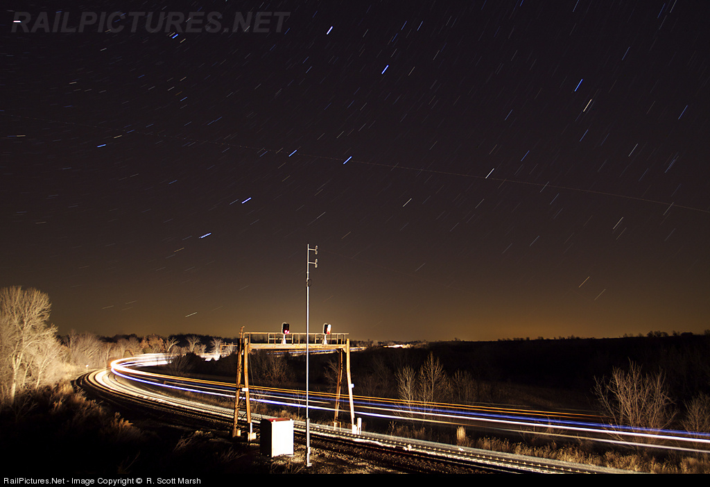
Now That's More Like It
What has continued to shock me in the current round of re-signaling is how much perfectly good hardware is simply scrapped for no apparent reason. Sometimes its as if the railroads just liking to be contrary, replacing bridges or cantilevers with masts, or masts with cantilevers and bridges. Often the old stuff is just a bucket of rust, other times it is barely 1 or 2 decades old with several more left in it. Well I noticed this little photo taken on a former ATSF main line where a classic ATSF steel beam signal gantry was outfitted with brand new Darth Vadar type heads. Yeah its not as nice as the original semaphores, but at least they made some use of the existing infrastructure.


Monday, January 30, 2012
PRR Main Line Survey 2010 Part 11 (STATE to CORK )
If you happened to enjoy my 10 part epic survey on the Pennsylvania Railroad Main Line between Philadelphia and Pittsburgh that just concluded I will be the first to admit that it was not exactly comprehensive as it was conducted in the westbound direction only. Last year I found myself in a position to at least partially rectify that situation by taking an eastbound journey on the Amtrak owned portion between Philadelphia and Harrisburg which had undergone some changes in the preceding year.
Anyway you can read most of the basic information about signaling on the old Main Line on the first part of the 2009 survey so I will hopefully be able to breeze through the 2010 inverse survey in a much more compact fashion. The quality of the photos is a bit more hit and miss due to the fact that I had to often shoot through two layers of glass and the weather was overcast. I know it doesn't work for some people, but you can always try the 1992 Amtrak diagrams starting at STATE interlocking as a line guide, although with the creeping re-signaling effort it is increasingly out of date. I will be drawing from the photos listed in this gallery which are in chronological order.
This segment of Part -1 will include Harrisburg to Lancaster, which was recently re-signaled.
Before we begin I have the opportunity to show off the Cab Signal Display Unit (CDU) that has been installed in most Amtrak locomotives and cab cars. The new CDUs work with the old PRR era pulse code cab signaling system (CSS) as well as the new ACSES track speed enforcement system which is still in limited service.
In this photo we can see a closeup of the new CDU with the cab signal indications being displayed via a miniature Amtrak type colourized position light over the signal speed digital readout. This is the speed determined by the CSS pulse codes, in this case 20mph for the Restricting cab signal (which is also displayed). Below the signal speed is the track speed, which would be determined by the ACSES system that is currently cut out as it is not installed anywhere on the Harrisburg Line. I think the orange LED bars under the speed readouts are some sort of countdown until there is a penalty brake application as the engineer has to both acknowledge any CSS drop, but also make a set brake reduction. The ACSES system only requires a specific braking rate, not a specific reduction.

Here is a wider view showing how the CDU is mounted in the cab of a Budd Metroliner cab car, just over the speedometer. Yes that is a GG-1 in the background. #4859 is on display at the Harrisburg Station to commemorate its honor of hauling the first electric train to Harrisburg in 1939.

Here is a video of the CDU freaking out after having been left on in the non-operating cab-car cab. When at Restricting the CDU demands periodic acknowledgment and this is what it does when it doesn't get it.
Alright, enough talk. It's time to begin our journey eastbound. Here the train has just left the Harrisburg station and has navigated the main part of STATE interlocking. Running from station track 7 to main track 1 the train makes a reverse move over the 101 switch. All points at STATE are pneumatic.

The 100L and 102L dwarf signals for westbound traffic into STATE. The main part of state is entirely Slow speed moves (15mph). Unfortunately due to some other states refusing high speed rail stimulus funds Amtrak was able to get additional monies to rebuild STATE interlocking over the next few years to eliminate the 15mph speed on at least the two main tracks. How this will affect the air operated points, the doubleslip switch and the Model 14 machine is not known at this time, but I expect it to be a job similar to CORK with a panel replacing the machine and all electric switches being employed (although STATE does flood every couple of years which gives air machines a slight advantage).

The 123 switch was original provided to allow trains on what was the freight only Columbia Branch (now the Norfolk Southern Royalton Branch) to access the Main Line. This branch ran parallel to the Main Line between here and ROY interlocking via the third track of the RoW so at least by the end of the PRR the Main Line between STATE and ROY was not 3 tracks, but one double track line and one single track line. In the 1992 diagram the connection via the 121 switch (marked as the F&G track) was still in place. In the original interlocking diagram you can see how it worked back in the day. Now only a shadow of the 121 switch remains and the 123 switch is rusty from disuse as it duplicates the function of the previous 101 switch. For a while it saw use for shunting movements pulling cars out of the express freight facility to the left, but Amtrak got out of that business in 2005.

The 120L is STATE's westbound home signal and one of the few high signals in the interlocking. This currently protects the 123 switch and acts as a distant for the 100L and 102L signals at the main section of the interlocking. As all moves in STATE ate slow speed the 120L tends to display / over ? for Approach Slow. It has a vestigial lower | for Medium Clear or Approach Medium for trains that were routed over the 121 switch on the F&G track.

This section of track between STATE and ROY was the first to be re-signaled under Rule 562, Cab Signals without fixed wayside signals. However Amtrak provided fixed wayside distants so that trains with failed cab signals could approach interlockings without preparing to stop. One of these are the 1015 signal for westbound movements approaching state. Both are new and of the Colourized Position type. The signal on the right displays the basic ABS aspects as the 120L at STATE lacks any diverging routes. The signal on the left can only display Stop and Proceed and Approach as the reverse direction 122L signal at STATE can only display slow speed indications. The signal on the right has a very diminutive numberplate that was installed by Amtrak under a previous refurbishment while new signal on the left has a new full size plate. On the far right is the 18W color light signal for the NS Royalton Branch. This is the distant signal to CP-CAPITOL.

Anyway you can read most of the basic information about signaling on the old Main Line on the first part of the 2009 survey so I will hopefully be able to breeze through the 2010 inverse survey in a much more compact fashion. The quality of the photos is a bit more hit and miss due to the fact that I had to often shoot through two layers of glass and the weather was overcast. I know it doesn't work for some people, but you can always try the 1992 Amtrak diagrams starting at STATE interlocking as a line guide, although with the creeping re-signaling effort it is increasingly out of date. I will be drawing from the photos listed in this gallery which are in chronological order.

This segment of Part -1 will include Harrisburg to Lancaster, which was recently re-signaled.
Before we begin I have the opportunity to show off the Cab Signal Display Unit (CDU) that has been installed in most Amtrak locomotives and cab cars. The new CDUs work with the old PRR era pulse code cab signaling system (CSS) as well as the new ACSES track speed enforcement system which is still in limited service.
In this photo we can see a closeup of the new CDU with the cab signal indications being displayed via a miniature Amtrak type colourized position light over the signal speed digital readout. This is the speed determined by the CSS pulse codes, in this case 20mph for the Restricting cab signal (which is also displayed). Below the signal speed is the track speed, which would be determined by the ACSES system that is currently cut out as it is not installed anywhere on the Harrisburg Line. I think the orange LED bars under the speed readouts are some sort of countdown until there is a penalty brake application as the engineer has to both acknowledge any CSS drop, but also make a set brake reduction. The ACSES system only requires a specific braking rate, not a specific reduction.

Here is a wider view showing how the CDU is mounted in the cab of a Budd Metroliner cab car, just over the speedometer. Yes that is a GG-1 in the background. #4859 is on display at the Harrisburg Station to commemorate its honor of hauling the first electric train to Harrisburg in 1939.

Here is a video of the CDU freaking out after having been left on in the non-operating cab-car cab. When at Restricting the CDU demands periodic acknowledgment and this is what it does when it doesn't get it.
Alright, enough talk. It's time to begin our journey eastbound. Here the train has just left the Harrisburg station and has navigated the main part of STATE interlocking. Running from station track 7 to main track 1 the train makes a reverse move over the 101 switch. All points at STATE are pneumatic.

The 100L and 102L dwarf signals for westbound traffic into STATE. The main part of state is entirely Slow speed moves (15mph). Unfortunately due to some other states refusing high speed rail stimulus funds Amtrak was able to get additional monies to rebuild STATE interlocking over the next few years to eliminate the 15mph speed on at least the two main tracks. How this will affect the air operated points, the doubleslip switch and the Model 14 machine is not known at this time, but I expect it to be a job similar to CORK with a panel replacing the machine and all electric switches being employed (although STATE does flood every couple of years which gives air machines a slight advantage).

The 123 switch was original provided to allow trains on what was the freight only Columbia Branch (now the Norfolk Southern Royalton Branch) to access the Main Line. This branch ran parallel to the Main Line between here and ROY interlocking via the third track of the RoW so at least by the end of the PRR the Main Line between STATE and ROY was not 3 tracks, but one double track line and one single track line. In the 1992 diagram the connection via the 121 switch (marked as the F&G track) was still in place. In the original interlocking diagram you can see how it worked back in the day. Now only a shadow of the 121 switch remains and the 123 switch is rusty from disuse as it duplicates the function of the previous 101 switch. For a while it saw use for shunting movements pulling cars out of the express freight facility to the left, but Amtrak got out of that business in 2005.


The 120L is STATE's westbound home signal and one of the few high signals in the interlocking. This currently protects the 123 switch and acts as a distant for the 100L and 102L signals at the main section of the interlocking. As all moves in STATE ate slow speed the 120L tends to display / over ? for Approach Slow. It has a vestigial lower | for Medium Clear or Approach Medium for trains that were routed over the 121 switch on the F&G track.

This section of track between STATE and ROY was the first to be re-signaled under Rule 562, Cab Signals without fixed wayside signals. However Amtrak provided fixed wayside distants so that trains with failed cab signals could approach interlockings without preparing to stop. One of these are the 1015 signal for westbound movements approaching state. Both are new and of the Colourized Position type. The signal on the right displays the basic ABS aspects as the 120L at STATE lacks any diverging routes. The signal on the left can only display Stop and Proceed and Approach as the reverse direction 122L signal at STATE can only display slow speed indications. The signal on the right has a very diminutive numberplate that was installed by Amtrak under a previous refurbishment while new signal on the left has a new full size plate. On the far right is the 18W color light signal for the NS Royalton Branch. This is the distant signal to CP-CAPITOL.


Sunday, January 22, 2012
Great Northern Railway Signaling: Then and Now
The reason for this Then and Now post is because I recently completed a trip via Amtrak's Empire Builder that included a trip over the BNSF Senic Subdivision which includes, among other things, the famous Cascade Tunnel, longest in the United States. Along this trip I accounted for the "now" portion of the signaling by taking almost 400 photos from the rear of the train documenting almost the entire Subdivision except for a section around Everett where I had to go get dinner.
The "Then" portion of this post came up when I found a 4 part YouTube video series taken by a young boy whose father was a block operator for the Great Northern Railway in the period between 1957 and 1971. The 8mm home movies show mostly GN trains, but does pay a good deal of attention to signaling and train orders with some shots inside the Skykomish block station and a sound track that consists of dispatcher-to-train communications recorded on a reel-to-reel tape ,achine. The Skykomish office is shown at the very beginning of the second part and shows the 4-level table interlocking machine that controls the local siding as well as a CTC display board that at least reports train positions (a unit level panel was not shown).
What is today known as the Senic Subdivision exemplifies the model of a North American single track railroad. The Main Track is broken up by 1-2 mile long passing sidings, which today are controlled by CTC, but in that time were usually worked by the crews using hand throw switches and written Train Orders. The Cascade Tunnel was built in 1929 and until 1957 was worked by electric locomotives running in a special district between Skykomish and Wenatchee. Therefore the siding and yard at Skykomish were given the luxury of both power signaling and an on site train order station. Even after the electrification was replaced by a ventilation system for diesels, the Skykomish block station remained in service as it still had local and CTC control duties and the yard was still needed as a helper base. Also, the operator at Skykomish had the important task of controlling the ventilation fans in the tunnel.
Here are the links to the 4 videos (remember part 2 starts off with both "tower" footage and recorded "tower" audio).
My 2011 photos can be found here.
The photos covering the parts most frequently seen in the videos begin here and you can just keep clicking next. One interesting bit of signaling I wanted to cover was that of the Cascade Tunnel itself. The tunnel is 8 miles long, but since only one train can navigate the tunnel at a time due to ventilation constraints it functions as one long absolute block. Speed is only 25 mph so that combined with the need to vent the tunnel for up to 20 minutes after an eastbound passage makes the limiting capacity constraint on the line. The interesting bit is that to keep the air blowing in the right direction a door is closed on the fan plant end until just before the train exits the tunnel. The door is unable to be interlocked with the signaling system because it must open so close to when the train exits that there is might not be enough room for the train to stop should it fail to do so. For this reason a spare door is on hand in case the main door were to suffer a catastrophic failure. Such a failure has only happened once since 1957.
Here is a video taken from the rear of the Empire Builder in the final 1/4 mile of its transit of the tunnel as it passes through the fan plant and then out past the westbound absolute signal. The door opens about at the point where the video begins.
And here is another video showing the amount of time between the door opening and a train passing it (40 seconds).
Enjoy.
The "Then" portion of this post came up when I found a 4 part YouTube video series taken by a young boy whose father was a block operator for the Great Northern Railway in the period between 1957 and 1971. The 8mm home movies show mostly GN trains, but does pay a good deal of attention to signaling and train orders with some shots inside the Skykomish block station and a sound track that consists of dispatcher-to-train communications recorded on a reel-to-reel tape ,achine. The Skykomish office is shown at the very beginning of the second part and shows the 4-level table interlocking machine that controls the local siding as well as a CTC display board that at least reports train positions (a unit level panel was not shown).
What is today known as the Senic Subdivision exemplifies the model of a North American single track railroad. The Main Track is broken up by 1-2 mile long passing sidings, which today are controlled by CTC, but in that time were usually worked by the crews using hand throw switches and written Train Orders. The Cascade Tunnel was built in 1929 and until 1957 was worked by electric locomotives running in a special district between Skykomish and Wenatchee. Therefore the siding and yard at Skykomish were given the luxury of both power signaling and an on site train order station. Even after the electrification was replaced by a ventilation system for diesels, the Skykomish block station remained in service as it still had local and CTC control duties and the yard was still needed as a helper base. Also, the operator at Skykomish had the important task of controlling the ventilation fans in the tunnel.
Here are the links to the 4 videos (remember part 2 starts off with both "tower" footage and recorded "tower" audio).
My 2011 photos can be found here.
The photos covering the parts most frequently seen in the videos begin here and you can just keep clicking next. One interesting bit of signaling I wanted to cover was that of the Cascade Tunnel itself. The tunnel is 8 miles long, but since only one train can navigate the tunnel at a time due to ventilation constraints it functions as one long absolute block. Speed is only 25 mph so that combined with the need to vent the tunnel for up to 20 minutes after an eastbound passage makes the limiting capacity constraint on the line. The interesting bit is that to keep the air blowing in the right direction a door is closed on the fan plant end until just before the train exits the tunnel. The door is unable to be interlocked with the signaling system because it must open so close to when the train exits that there is might not be enough room for the train to stop should it fail to do so. For this reason a spare door is on hand in case the main door were to suffer a catastrophic failure. Such a failure has only happened once since 1957.
Here is a video taken from the rear of the Empire Builder in the final 1/4 mile of its transit of the tunnel as it passes through the fan plant and then out past the westbound absolute signal. The door opens about at the point where the video begins.
And here is another video showing the amount of time between the door opening and a train passing it (40 seconds).
Enjoy.
Friday, January 20, 2012
PRR Main Line Survey 1985 Edition! Parts 3 and 4
No, I didn't go back in time, but with the help of YouTube we can do the next best thing. There is a set of railfan head end videos taken in 1985 of the PRR Main Line taken from the cab of Amtrak's westbound Pennsylvanian. I am in possession of Part 1 from PENN to STATE, but in a wonderful twist of good fortune parts 3 and 4 have popped up on YouTube. Part 3 runs from Huntington to Johnstown and part 4 runs from Johnstown to Pittsburgh.
In the mid 1980's the PRR Main Line was still in the good old days where the old line signal departments were trying to keep the heritage styles consistent on the main. There is not a single color light style signal to be seen throughout this entire video. However, the CTC project from Johnstown to Pittsburgh had been in place for some years and the project east of Altoona is well under way. However starting in Huntington, although the 3-track tower controlled line has been reduced to two, a few towers are still open (GRAY and HUNT) and pole lines are still in service on part of the route. Of course between ALTO and C the block operation would be in service for another decade, but that two has largely disappeared with what NS' desecration of east slope so this video is a valuable resource there as well.
Perhaps the most useful tidbits are the original tower control MO and SO interlockings, and a view of what the RoW approaching Pittsburgh looked like before it had a busway plopped down on half of it (well, the 90's extension, not the original busway section).
Anyway, enjoy the movies. I'll post the other parts if they ever become available.
In the mid 1980's the PRR Main Line was still in the good old days where the old line signal departments were trying to keep the heritage styles consistent on the main. There is not a single color light style signal to be seen throughout this entire video. However, the CTC project from Johnstown to Pittsburgh had been in place for some years and the project east of Altoona is well under way. However starting in Huntington, although the 3-track tower controlled line has been reduced to two, a few towers are still open (GRAY and HUNT) and pole lines are still in service on part of the route. Of course between ALTO and C the block operation would be in service for another decade, but that two has largely disappeared with what NS' desecration of east slope so this video is a valuable resource there as well.
Perhaps the most useful tidbits are the original tower control MO and SO interlockings, and a view of what the RoW approaching Pittsburgh looked like before it had a busway plopped down on half of it (well, the 90's extension, not the original busway section).
Anyway, enjoy the movies. I'll post the other parts if they ever become available.
Tuesday, January 3, 2012
PHOTOS: METRA UD Tower
UD Tower in Joliet, Illinois is located at the diamond crossing of the former ATSF (Santa Fe) and the Chicago and Alton main lines and the former Rock Island main line. Of course none of their original railroads exist so today the Rock Island line is owned by the Chicago commuter rail authority METRA to the east and the Iowa Interstate, the line ATSF morphed into BNSF and the Alton was bought by the Gulf Mobile and Ohio, which merged with the Illinois Central which spun off the portion south of Joliet to the Southern Pacific which was then merged into the Union Pacific and with the part north of the city getting folded into Canadian National after the CNIC merger. Finally, both METRA and Amtrak use the former Alton main as guest railroads.
The layout is fairly simple. The ATSF and Alton lines run roughly north-south through the City of Joliet and come together in to an elevated 4-track corridor that then cross the former Rock Island main running east-west at a diamond crossing. This elevated diamond crossing and rail corridor was part of a 1912 project to construct a new Union Station at Joliet serving all three of the major railroads in grade separated splendor. Along with this station came a new interlocking tower to control it which was UD which I assume stands for Union Diamonds or something like that. Like the other Chicago area towers diamonds were the name of the game and in its heyday UD featured a 4x4 grid of diamonds where the 2 main lines met. However today that has been reduced to a 4x1 as the Rock Island really took it on the chin, eventually going bankrupt and nearly being abandoned.
Even tho the 3 main lines were separate UD contained ample crossover facilities between the lines that were used to varying degrees. People might know UD from old pictures usually involving the Southwest Chief and the large signal gantries spanning the parallel main lines covered in semaphore signals. Today the semaphores are long gone, but some of the crossovers do still exist even if they aren't all used much. Today UD sees freight service on all of its lines, but primarily the BNSF route which is a major double stack intermodal route into the BNSF Corwith yard complex. The former Alton line does see some through fright, but it is largely a passenger route with a peak period METRA Heritage service from here to Chicago Union Station , but also Amtrak "Lincoln Service" to St Louis along with the Texas Eagle long distance train. This line is being upgraded to a high speed corridor with 110mph operation. The crossing route sees all day METRA service as part of their Rock Island district so Joliet serves as the terminal of two independent Metra services.
This tower is officially located in the "Western Region" of the United States where I am not properly qualified so I am hazy on various details such as ownership or when parts of the interlocking were modified so I apologize in advance for any missing or inaccurate information about this tower. The following description will contain two primary sources of photos. The first come from an Amtrak trip I took to St Louis in 2005 and cover the Alton alignment in both directions. The second were provided by a railroad affiliate and detail the inside of the tower taken around 2007 or 2008.
I also do not as of yet have a historic interlocking diagram for UD tower, although that might change and I would post it right here in an update.
You can see the entire set of photos here which I have left in their original resolution to help show off the detail contained within. Let me know if you would prefer that I linked to the images directly so that one's browser can scale them properly.
We will begin on the Alton Main running northeast to southwest (railroad east west). Here we are facing UD interlocking (the tower is visible in the distance) on the Alton Main just before it ramps up to the grade seperated alignment at the station. The signals before us are the start of the CN controlled CTC territory. Between here and the limits of UD the line could be considered under ABS rules.

Over on the left we see the rear of UDs home signals and the BNSF ABS entrance signals. At the time the BNSF main was running under single direction ABS rules east of here with a pole line for communications, however overhead photos confirm the both the searchlight and target type color light signals have been replaced by bi-directional traffic lights. Lever numbers are 10 for the reverse direction dwarf, 8 for a straight route on the mast and 6 for a diverging route (which was originally provided by a subsidiary signal).

Moving a bit further and looking back away from the interlocking we see the rear of the westbound home signals on the Alton into UD. The mast signal has been replaced by a modern traffic light type signal which the reverse direction dwarf is an older US&S N-2 unit. Lever number for the dwarf is 11, straight route on the mast is 2 and the diverging route is 3 or 4 depending on an Alton or Santa Fe lineup.

Searchlight automatic signal 72 acts as an exit signal and governs the short distance between UDs limits and the start of CN CTC. We can also see a facing point turnout over on the BNSF main which is worked by levers 14 and 15..

Moving on we find UD's remaining double-slip switch which allows trains on the BNSF route to access the Alton Line. As the tracks curve north of the tower the "diverging" route actually appears to continue on straight. The point of this ladder and a matching one on the opposite side of the interlocking plant was to allow passenger trains on the Alton to platform on the holdout platform at Union Station. For whatever reason this strategy is no longer employed at UD and the matching double slip ladder on the west end of the interlocking was actually removed.
UD is a heavily zoned interlocking with multiple signals along each route. The doubleslip switch and the BNSF facing crossover are in the eastern zone. to the right we can see a rock Island style target color light signal that marks the entrance to the central zone that handles the diamonds. This is a Rock Island style as the US&S supplied triangular target signal has large shade hoods which was a forerunner of today's Darth Vader signal. The doubleslip turnouts are control be levers 40, 41, 43, 47 and 48. The Rock Island style mast is 60 and the dwarf across from it is 59.

>Looking back in the other direction at the doubleslip we can see two floating dwarfs on the reverse direction tracks. These are numbers 36 (Alton) and 31 (Santa Fe). I am sure these used to protect some form of additional turnouts or whatnot.

Here we see UD tower with the east signal gantry. One interesting thing is the presence of subsidiary signals to provide call-on aspects for trains. The BNSF eastbound mast has two heads for the diverging route onto the Alton. This is route signaling territory so that is why the signals here have so much fewer heads than on eastern railroads. From left to right we have the eastbound Alton signal, lever 52 main and 54 subsidiary, then the reverse direction Alton signal (a "high" dwarf) controlled by lever 55, then the westbound Alton "central zone" signal under lever 61 then the eastbound BNSF signal under lever 57 for the main route and levers 56 and 58 for the other two Alton routes.
In this picture we can also see the arrangements for passengers boarding the trains on the Alton tracks. Due to the lack of any under or overpasses trains on the BNSF must be held to allow passengers to board or alight from trains via the duckboards.

Eastbound view of the east gantry showing the front face of the two headed BNSF signal, the eastbound Alton main signal and both subsidiary signals.

The tower is located at the point of the diamond crossings across from the Union Station building which was last renovated around 1990 and apparently is quite nice inside despite the primitive platform conditions. The lever 60 signal on the BNSF is in place to allow trains to be held clear of the passenger platforms so passengers can cross the tracks. There is a closer signal on the edge of the platform, 64, that actually protects the diamond. On the eastbound tracks we see reverse direction dwarf signals 63 (BNSF) and 62 (Alton).

Side view of UD with a Metra MoW truck painted to look like a high visibility vest. The tower is quite long to fit in the lever frame and also tall for all of the relays in the first floor.

The layout is fairly simple. The ATSF and Alton lines run roughly north-south through the City of Joliet and come together in to an elevated 4-track corridor that then cross the former Rock Island main running east-west at a diamond crossing. This elevated diamond crossing and rail corridor was part of a 1912 project to construct a new Union Station at Joliet serving all three of the major railroads in grade separated splendor. Along with this station came a new interlocking tower to control it which was UD which I assume stands for Union Diamonds or something like that. Like the other Chicago area towers diamonds were the name of the game and in its heyday UD featured a 4x4 grid of diamonds where the 2 main lines met. However today that has been reduced to a 4x1 as the Rock Island really took it on the chin, eventually going bankrupt and nearly being abandoned.
Even tho the 3 main lines were separate UD contained ample crossover facilities between the lines that were used to varying degrees. People might know UD from old pictures usually involving the Southwest Chief and the large signal gantries spanning the parallel main lines covered in semaphore signals. Today the semaphores are long gone, but some of the crossovers do still exist even if they aren't all used much. Today UD sees freight service on all of its lines, but primarily the BNSF route which is a major double stack intermodal route into the BNSF Corwith yard complex. The former Alton line does see some through fright, but it is largely a passenger route with a peak period METRA Heritage service from here to Chicago Union Station , but also Amtrak "Lincoln Service" to St Louis along with the Texas Eagle long distance train. This line is being upgraded to a high speed corridor with 110mph operation. The crossing route sees all day METRA service as part of their Rock Island district so Joliet serves as the terminal of two independent Metra services.
This tower is officially located in the "Western Region" of the United States where I am not properly qualified so I am hazy on various details such as ownership or when parts of the interlocking were modified so I apologize in advance for any missing or inaccurate information about this tower. The following description will contain two primary sources of photos. The first come from an Amtrak trip I took to St Louis in 2005 and cover the Alton alignment in both directions. The second were provided by a railroad affiliate and detail the inside of the tower taken around 2007 or 2008.
I also do not as of yet have a historic interlocking diagram for UD tower, although that might change and I would post it right here in an update.
You can see the entire set of photos here which I have left in their original resolution to help show off the detail contained within. Let me know if you would prefer that I linked to the images directly so that one's browser can scale them properly.
We will begin on the Alton Main running northeast to southwest (railroad east west). Here we are facing UD interlocking (the tower is visible in the distance) on the Alton Main just before it ramps up to the grade seperated alignment at the station. The signals before us are the start of the CN controlled CTC territory. Between here and the limits of UD the line could be considered under ABS rules.

Over on the left we see the rear of UDs home signals and the BNSF ABS entrance signals. At the time the BNSF main was running under single direction ABS rules east of here with a pole line for communications, however overhead photos confirm the both the searchlight and target type color light signals have been replaced by bi-directional traffic lights. Lever numbers are 10 for the reverse direction dwarf, 8 for a straight route on the mast and 6 for a diverging route (which was originally provided by a subsidiary signal).

Moving a bit further and looking back away from the interlocking we see the rear of the westbound home signals on the Alton into UD. The mast signal has been replaced by a modern traffic light type signal which the reverse direction dwarf is an older US&S N-2 unit. Lever number for the dwarf is 11, straight route on the mast is 2 and the diverging route is 3 or 4 depending on an Alton or Santa Fe lineup.

Searchlight automatic signal 72 acts as an exit signal and governs the short distance between UDs limits and the start of CN CTC. We can also see a facing point turnout over on the BNSF main which is worked by levers 14 and 15..

Moving on we find UD's remaining double-slip switch which allows trains on the BNSF route to access the Alton Line. As the tracks curve north of the tower the "diverging" route actually appears to continue on straight. The point of this ladder and a matching one on the opposite side of the interlocking plant was to allow passenger trains on the Alton to platform on the holdout platform at Union Station. For whatever reason this strategy is no longer employed at UD and the matching double slip ladder on the west end of the interlocking was actually removed.
UD is a heavily zoned interlocking with multiple signals along each route. The doubleslip switch and the BNSF facing crossover are in the eastern zone. to the right we can see a rock Island style target color light signal that marks the entrance to the central zone that handles the diamonds. This is a Rock Island style as the US&S supplied triangular target signal has large shade hoods which was a forerunner of today's Darth Vader signal. The doubleslip turnouts are control be levers 40, 41, 43, 47 and 48. The Rock Island style mast is 60 and the dwarf across from it is 59.

>Looking back in the other direction at the doubleslip we can see two floating dwarfs on the reverse direction tracks. These are numbers 36 (Alton) and 31 (Santa Fe). I am sure these used to protect some form of additional turnouts or whatnot.

Here we see UD tower with the east signal gantry. One interesting thing is the presence of subsidiary signals to provide call-on aspects for trains. The BNSF eastbound mast has two heads for the diverging route onto the Alton. This is route signaling territory so that is why the signals here have so much fewer heads than on eastern railroads. From left to right we have the eastbound Alton signal, lever 52 main and 54 subsidiary, then the reverse direction Alton signal (a "high" dwarf) controlled by lever 55, then the westbound Alton "central zone" signal under lever 61 then the eastbound BNSF signal under lever 57 for the main route and levers 56 and 58 for the other two Alton routes.
In this picture we can also see the arrangements for passengers boarding the trains on the Alton tracks. Due to the lack of any under or overpasses trains on the BNSF must be held to allow passengers to board or alight from trains via the duckboards.

Eastbound view of the east gantry showing the front face of the two headed BNSF signal, the eastbound Alton main signal and both subsidiary signals.

The tower is located at the point of the diamond crossings across from the Union Station building which was last renovated around 1990 and apparently is quite nice inside despite the primitive platform conditions. The lever 60 signal on the BNSF is in place to allow trains to be held clear of the passenger platforms so passengers can cross the tracks. There is a closer signal on the edge of the platform, 64, that actually protects the diamond. On the eastbound tracks we see reverse direction dwarf signals 63 (BNSF) and 62 (Alton).

Side view of UD with a Metra MoW truck painted to look like a high visibility vest. The tower is quite long to fit in the lever frame and also tall for all of the relays in the first floor.

Wednesday, December 28, 2011
PRR Main Line Survey 2009 Part 10 (CP-RADE to CP-WEST PITT)
Well for those of you who have stayed with me on this odyssey of signaling across Pennsylvania we have reached the final leg of our Journey between Greensburg, PA and Pittsburgh itself. The daylight was beginning to fail at this point so I apologize for the decreased photographic quality.
The relevant track charts for this segment can be found here.


Beginning at Greensburg it is worthwhile mentioning an interesting feature of the right of way that important to the signaling in the area. You may have noticed in part 3.2 that SW tower at Southwest Junction had a western section where the 4-track right of way shrank to three tracks for a pair of tunnels. I mentioned that past CP-CONPIT the main line took off overland across a plateau to reach Pittsburgh directly instead of following the Conemaugh River. This resulted in a steeper grade profile as well as a number of bottlenecks in the Greensburg area in the form of tunnels. The first was located directly east of the station and was eliminated in the 1890's, the second set of tunnels hung around a lot longer and remained an operational headache.
Known as the Radebaugh tunnels after the community west of Greensburgh (which had its own tunnel) the first was built in 1852 as part of the original Main Line project and nearly derailed the entire enterprise as the cost and delays of tunneling began to give the Philadelphia area investors cold feet. The original tunnel was very tight and built on a curvy alignment through the local drainage divide between the Conemaugh and Monongahela rivers. In the 1890's a new, larger tunnel was built on a more direct alignment, at first replacing the original tunnel until traffic levels pressed the 1850's bore back into service to carry a third main track. You can see the two tunnel alignments on this Wiki Map.
http://www.wikimapia.org/#lat=40.311390 ... =Radebaugh
Still, three tunnel tracks on a four track line a bottleneck makes, but adding a 4th track or simply removing the tunnel never became a priority for the PRR so they did the best they could with interlocking design. Directly on each side of the new 1890's tunnel the 3 tracks shrank to 2 via a parallel shift layout with freight track 1 having the forced diverge at each. Track #4, also designated for freight, used the pimple alignment of the 1850's tunnel allowing the designated passenger tracks 2 and 3 the straight shot through.
In 1965 the waning PRR showed some of its old magic when new tunnel was daylighted in a project where the overburden was first removed and then in the space of 11 hours the tunnel roof was blasted and track re-laid with the RoW being widened over time. Track #4 remained in use through the old tunnel on the alternate alignment until the deluge from Hurricane Agnes collapsed it in 1972. The 1980 CTC project under Conrail did the rest permanently making the line two-tracks.
Anyway as I said all this was relevant to signaling as both SW tower east of the tunnels and RG tower, west of the tunnels, were built to deal with the bottleneck. Here we see the location of the new tunnel now just an open cut. In the right of the picture there is an interesting signal facing away from us for traffic on the branch line which is labeled R08. This is a distant signal to the upcoming interlocking and a vestage of the old PRR Manual Block system.

In this view taken in 2004 we see R08 in its original configuration as a PRR Position Light. This signal could display, Approach Medium, Approach and Caution. Approach Medium would display when a train coming off the branch line was had a proceed indication like Medium Clear and Approach would display if the interlocking was showing a Stop indication. Both would show that the track circuited approach block was clear, however if it was not the signal would display a Caution signal which on a PRR PL is \ over a marker light as shown in this photo.

Under NORAC the old PRR signal aspect was joined by other fixed distant styles such as the traditional yellow semaphore held at / with an (A) plate and a single yellow lamp also with an (A) plate. As the owner of the interlocking is responsible for maintaining the distant NS eventually got fed up with supporting a full PRR PL at R08 and "upgraded" it with the single yellow lamp variety sometime around 2006. Here is a front view of the new Approach Restricting signal from Railpictures.net. Not quite the same is it.

Ok, finally moving on we get to CP-RADE, formerly RG (RadebauGh) interlocking. Built in 1890 as part of the tunnel project RG complimented its neighbor SW and there were actually no intermediate signals between the two. The two towers had to work together to signal trains on the bi-directional tunnel tracks. When built in 1890 electricity was still new-fangled so there wasn't much of a power grid around to power the electro-pneumatic interlocking machine, air operated points and track circuits so RG was actually build with a railroad owned and operated power plant behind it. Pretty amazing that back in the day railroads had to act as both telecom outfits and power companies. Talk about vertical integration! Here is the original diagram of RG, you can see the power plant behind the tower.

Regrettably no trace of RG tower of the power plant remain today, but unlike SW interlocking, RG interlocking is still around in the form of CP-RADE. CP-RADE lost its westbound PRR signal gantry shortly after Norfolk Southern took over Conrail in 1999. The C&S department still had a commitment to target type signals, but was forced to buy from the Safetran catalogue instead of US&S so we have the Safetran style modular lamps with a circular mounting.

The main signal were also re-located a few hundred feet east to provide better visibility for approaching trains. The branch line signal remained at the same location. Note supports for the old PL gantry.

Points were left pneumatic. The switch to the Southwestern Pennsylvania Railroad owned branchline is good for 30mph movements.

The airline looks freshly painted next to the relay hut.

The eastbound signal remains a PRR PL.

The 3284 automatic distant to CP-RADE was also replaced around 2000 and I remember finding photos alerting me to the loss at that time. Signals next to a grade crossing of course creates another popular railfan location. BTW look at the grade profile.

The 3304 automatics were replaced in the Conrail era.

The surviving PRR gantry holding automatic signal 3326 used to be the westbound home signal of CP Interlocking at Larimer, PA. This was another mixing bowl interlocking where the passenger traffic was shifted to tracks 4 and 3 and the freight to tracks 1 and 2. This was due to the upcoming Pitcarin Yard and the desire not to have trains crawling into the yard foul the interlocking plant for passenger trains needing to cross over. For some reason this signal supports 4-block signaling westbound despite a standard sized block length.

Automatic signal 3346 is the distant to CP-TRAFF.

The relevant track charts for this segment can be found here.
Beginning at Greensburg it is worthwhile mentioning an interesting feature of the right of way that important to the signaling in the area. You may have noticed in part 3.2 that SW tower at Southwest Junction had a western section where the 4-track right of way shrank to three tracks for a pair of tunnels. I mentioned that past CP-CONPIT the main line took off overland across a plateau to reach Pittsburgh directly instead of following the Conemaugh River. This resulted in a steeper grade profile as well as a number of bottlenecks in the Greensburg area in the form of tunnels. The first was located directly east of the station and was eliminated in the 1890's, the second set of tunnels hung around a lot longer and remained an operational headache.

Known as the Radebaugh tunnels after the community west of Greensburgh (which had its own tunnel) the first was built in 1852 as part of the original Main Line project and nearly derailed the entire enterprise as the cost and delays of tunneling began to give the Philadelphia area investors cold feet. The original tunnel was very tight and built on a curvy alignment through the local drainage divide between the Conemaugh and Monongahela rivers. In the 1890's a new, larger tunnel was built on a more direct alignment, at first replacing the original tunnel until traffic levels pressed the 1850's bore back into service to carry a third main track. You can see the two tunnel alignments on this Wiki Map.
http://www.wikimapia.org/#lat=40.311390 ... =Radebaugh
Still, three tunnel tracks on a four track line a bottleneck makes, but adding a 4th track or simply removing the tunnel never became a priority for the PRR so they did the best they could with interlocking design. Directly on each side of the new 1890's tunnel the 3 tracks shrank to 2 via a parallel shift layout with freight track 1 having the forced diverge at each. Track #4, also designated for freight, used the pimple alignment of the 1850's tunnel allowing the designated passenger tracks 2 and 3 the straight shot through.
In 1965 the waning PRR showed some of its old magic when new tunnel was daylighted in a project where the overburden was first removed and then in the space of 11 hours the tunnel roof was blasted and track re-laid with the RoW being widened over time. Track #4 remained in use through the old tunnel on the alternate alignment until the deluge from Hurricane Agnes collapsed it in 1972. The 1980 CTC project under Conrail did the rest permanently making the line two-tracks.
Anyway as I said all this was relevant to signaling as both SW tower east of the tunnels and RG tower, west of the tunnels, were built to deal with the bottleneck. Here we see the location of the new tunnel now just an open cut. In the right of the picture there is an interesting signal facing away from us for traffic on the branch line which is labeled R08. This is a distant signal to the upcoming interlocking and a vestage of the old PRR Manual Block system.

In this view taken in 2004 we see R08 in its original configuration as a PRR Position Light. This signal could display, Approach Medium, Approach and Caution. Approach Medium would display when a train coming off the branch line was had a proceed indication like Medium Clear and Approach would display if the interlocking was showing a Stop indication. Both would show that the track circuited approach block was clear, however if it was not the signal would display a Caution signal which on a PRR PL is \ over a marker light as shown in this photo.
Under NORAC the old PRR signal aspect was joined by other fixed distant styles such as the traditional yellow semaphore held at / with an (A) plate and a single yellow lamp also with an (A) plate. As the owner of the interlocking is responsible for maintaining the distant NS eventually got fed up with supporting a full PRR PL at R08 and "upgraded" it with the single yellow lamp variety sometime around 2006. Here is a front view of the new Approach Restricting signal from Railpictures.net. Not quite the same is it.
Ok, finally moving on we get to CP-RADE, formerly RG (RadebauGh) interlocking. Built in 1890 as part of the tunnel project RG complimented its neighbor SW and there were actually no intermediate signals between the two. The two towers had to work together to signal trains on the bi-directional tunnel tracks. When built in 1890 electricity was still new-fangled so there wasn't much of a power grid around to power the electro-pneumatic interlocking machine, air operated points and track circuits so RG was actually build with a railroad owned and operated power plant behind it. Pretty amazing that back in the day railroads had to act as both telecom outfits and power companies. Talk about vertical integration! Here is the original diagram of RG, you can see the power plant behind the tower.

Regrettably no trace of RG tower of the power plant remain today, but unlike SW interlocking, RG interlocking is still around in the form of CP-RADE. CP-RADE lost its westbound PRR signal gantry shortly after Norfolk Southern took over Conrail in 1999. The C&S department still had a commitment to target type signals, but was forced to buy from the Safetran catalogue instead of US&S so we have the Safetran style modular lamps with a circular mounting.

The main signal were also re-located a few hundred feet east to provide better visibility for approaching trains. The branch line signal remained at the same location. Note supports for the old PL gantry.

Points were left pneumatic. The switch to the Southwestern Pennsylvania Railroad owned branchline is good for 30mph movements.

The airline looks freshly painted next to the relay hut.

The eastbound signal remains a PRR PL.

The 3284 automatic distant to CP-RADE was also replaced around 2000 and I remember finding photos alerting me to the loss at that time. Signals next to a grade crossing of course creates another popular railfan location. BTW look at the grade profile.

The 3304 automatics were replaced in the Conrail era.

The surviving PRR gantry holding automatic signal 3326 used to be the westbound home signal of CP Interlocking at Larimer, PA. This was another mixing bowl interlocking where the passenger traffic was shifted to tracks 4 and 3 and the freight to tracks 1 and 2. This was due to the upcoming Pitcarin Yard and the desire not to have trains crawling into the yard foul the interlocking plant for passenger trains needing to cross over. For some reason this signal supports 4-block signaling westbound despite a standard sized block length.


Automatic signal 3346 is the distant to CP-TRAFF.

Saturday, December 24, 2011
PHOTOS: Amtrak THORN Tower
Those of you who read my earlier essays on the signaling of the PRR Main Line might remember a bit about THORN tower in Thorndale, PA (where else!). Situated at the junction of the original PRR Main Line and the Low Grade Extension of the Trenton Cutoff, THORN interlocking proper consisted of a 6-track full crossover with the two track Low Grade Extension to the east and a small yard and helper base to the west, both sandwiched in between the two main tracks of the Main Line. Today THORN tower remains active as part of Amtrak's Harrisburg Line having seen many changes over its 70 years in operation.
THORN tower was built in 1938 and at the time it represented a bold form if new technology on the traditionalist Pennsylvania Railroad. The PRR had been a strong proponent of the traditional block system with Block and Interlocking Stations spaced even intervals along the line with Block Operators passing trains from one to another. As the PRR was a wealthy railroad and could afford the expense of building interlocking plants where many other railroads would make do with hand throw switches and the Automatic Block System. As the cost of technology began to drop in relation to labor Centralized Traffic Control began to be embraced by PRR rivals such as New York Central. Intended to replace train orders on long single-track lines, CTC pulse-code technology could nevertheless allow multiple interlockings of any configuration to be worked from a single location. While the PRR would continue to rely on the individual Block Station until the end, it did install several significant CTC projects with THORN being one of them.
THORN's territory stretched from MP 25.3 to MP 36.6 on the Main Line and also included the Philadelphia and Trenton Low Grade Extension between those two points as well. In addition to its own namesake interlocking, THORN had CTC control over DOWNS, GLEN and DALE interlockings to the east and CALN interlocking to the west. While today CTC implies bi-directional operation, the PRR was content to use the technology for simple remote control and most of the routes were left operating under single direction ABS.
The Penn Central era brought some minor reductions to THORN's plant with the Low Grade extension being reduced to a single bi-directional track and the line between GLEN and PAOLI being reduced from 4 tracks to 3, with the center track being bi-directional.


Under Amtrak the plant shrank further with the Low Grade Extension being completely abandoned, the Thorndale yard being almost completely removed and the 3rd track between GLEN and PAOLI being ripped out due to the loss of through freight service on the Main Line in the early 1980's. However most of the interlocking layouts were kept the same due to the costs involved with modifying the logic. Here is how the territory looked in 1992.


In 1994 the closure of Paoli Shoppes due to massive PCB comtamination forced SEPTA to build a new terminal Yard in Frazer, PA for its popular R5 commuter service. This added a simple interlocking for trains to enter/exit the yard and to turn back just east of GLEN intelrocking. The old DALE interlocking, now little more than a Control Point was eliminated and the few local freight accessing the Main Line would queue up at the home signal at GLEN.
While even more changes are planned for the Harrisburg Line, in 2010 THORN and its territory are much the same as they were in 2005 when I was able to commission a survey of the tower and its interlocking plant. Some of the photos had to sit on ice for a few years, but they have been recently processed and posted for you all to enjoy. Photos that were releasable at the time were processed at a lower resolution due to the conventions of screen sizes and internet connectivity at the time.
THORN tower is an identical twin to the previously discussed COLA tower, which like THORN was a PRR CTC tower built in 1937. Both these towers were built in conjunction with the electrification of the PRR Main and Low Grade freight lines to Harrisburg. It is a two story brick building with no trademark bay window. It could be considered a forerunner of the 1940's towers built up and down the Northeast Corridor and discussed in the signalbox.org overseas section. The tower has a number of subtle art deco flourishes as well as a pair of interlocking illumination floodlights (one currently active). Also on the right side of the tower note the tower emergency horn which, in theory, can be used to stop trains moving through the plant.

The windows have all been replaced with modern types as this tower post-dates the large floor to ceiling windows that were so often butchered in modernization efforts. In 2005 a new backup diesel generator had been installed to provide interruptions to the local main grid.

Here is the east side of the tower showing the canopied entrance, Bilco doors to the basement and the operator's car.

Behind the tower we find the air plant consisting of three large kettle tanks and an old time drying unit.

THORN tower was built in 1938 and at the time it represented a bold form if new technology on the traditionalist Pennsylvania Railroad. The PRR had been a strong proponent of the traditional block system with Block and Interlocking Stations spaced even intervals along the line with Block Operators passing trains from one to another. As the PRR was a wealthy railroad and could afford the expense of building interlocking plants where many other railroads would make do with hand throw switches and the Automatic Block System. As the cost of technology began to drop in relation to labor Centralized Traffic Control began to be embraced by PRR rivals such as New York Central. Intended to replace train orders on long single-track lines, CTC pulse-code technology could nevertheless allow multiple interlockings of any configuration to be worked from a single location. While the PRR would continue to rely on the individual Block Station until the end, it did install several significant CTC projects with THORN being one of them.
THORN's territory stretched from MP 25.3 to MP 36.6 on the Main Line and also included the Philadelphia and Trenton Low Grade Extension between those two points as well. In addition to its own namesake interlocking, THORN had CTC control over DOWNS, GLEN and DALE interlockings to the east and CALN interlocking to the west. While today CTC implies bi-directional operation, the PRR was content to use the technology for simple remote control and most of the routes were left operating under single direction ABS.


The Penn Central era brought some minor reductions to THORN's plant with the Low Grade extension being reduced to a single bi-directional track and the line between GLEN and PAOLI being reduced from 4 tracks to 3, with the center track being bi-directional.


Under Amtrak the plant shrank further with the Low Grade Extension being completely abandoned, the Thorndale yard being almost completely removed and the 3rd track between GLEN and PAOLI being ripped out due to the loss of through freight service on the Main Line in the early 1980's. However most of the interlocking layouts were kept the same due to the costs involved with modifying the logic. Here is how the territory looked in 1992.


In 1994 the closure of Paoli Shoppes due to massive PCB comtamination forced SEPTA to build a new terminal Yard in Frazer, PA for its popular R5 commuter service. This added a simple interlocking for trains to enter/exit the yard and to turn back just east of GLEN intelrocking. The old DALE interlocking, now little more than a Control Point was eliminated and the few local freight accessing the Main Line would queue up at the home signal at GLEN.
While even more changes are planned for the Harrisburg Line, in 2010 THORN and its territory are much the same as they were in 2005 when I was able to commission a survey of the tower and its interlocking plant. Some of the photos had to sit on ice for a few years, but they have been recently processed and posted for you all to enjoy. Photos that were releasable at the time were processed at a lower resolution due to the conventions of screen sizes and internet connectivity at the time.
THORN tower is an identical twin to the previously discussed COLA tower, which like THORN was a PRR CTC tower built in 1937. Both these towers were built in conjunction with the electrification of the PRR Main and Low Grade freight lines to Harrisburg. It is a two story brick building with no trademark bay window. It could be considered a forerunner of the 1940's towers built up and down the Northeast Corridor and discussed in the signalbox.org overseas section. The tower has a number of subtle art deco flourishes as well as a pair of interlocking illumination floodlights (one currently active). Also on the right side of the tower note the tower emergency horn which, in theory, can be used to stop trains moving through the plant.

The windows have all been replaced with modern types as this tower post-dates the large floor to ceiling windows that were so often butchered in modernization efforts. In 2005 a new backup diesel generator had been installed to provide interruptions to the local main grid.

Here is the east side of the tower showing the canopied entrance, Bilco doors to the basement and the operator's car.

Behind the tower we find the air plant consisting of three large kettle tanks and an old time drying unit.

Subscribe to:
Posts (Atom)