Two examples of B&O Color Position Light signals that held on after re-signaling projects felled all of their neighbors, will finally meet the wrath of standardization. The first are GREENBELT interlocking on the Capitol Sub in suburban Maryland and the others are at OB (Ohio Bridge) CABIN on the Cincinnati Terminal Sub in Covington, KY.
GREENBELT was installed in 1992 to support a new intermodal MARC station. High level platforms at GREENBELT would make the station incompatible with CSX freight clearances so two station tracks were installed within the limits of a new interlocking. CSX was still in the practice of installing legacy signaling at the time and GREENBELT was therefore given modern style B&O CPLs in addition to other interlockings being installed in the DC area to support CTC and increased MARC service. In 2012 CSX, backed by some amount of government funding, embarked on another re-signaling spree in the DC area and ripped out all of the CPLs save for those at GREENBELT, probably due to some disagreement over how much the state should pay as the interlocking's sole use was to support MARC services. Anyway, in 2020 the issues were finally resolved and from what I have heard the CPL replacement project will wrap up sometime in June or July.
Back in 2018 I reported on the demise of the well known CPLs at KC JCT in Covington, KY and worked under the assumption that the adjacent CPLs at OB Cabin would also be replaced. Well it turns out I was wrong as for reasons unknown, the CPLs at OB Cabin hung on for a further two years with a planned retirement in mid-May 2020. Surprisingly, instead of masts or dwarfs or dwarf masts attached to the side of the bridge or the old gantry uprights, CSX has decided on some sort of super-signal bridge that has more in common with a tower crane than a railroad signal and might be the tallest railroad signal ever constructed
This will leave the single cantilever at WINTON PLACE and another adjacent Indiana and Ohio Railway interlocking as the only two remaining main line CPLs in the Cincinatti Area. Of course that's a downright luxury as the ENTIRE STATE OF MARYLAND, home of the Baltimore and Ohio itself, will now be completely devoid of main line CPLs. Think about that one :-(
A blog devoted to explaining the ins and outs of North American railroad signaling, past, present and future. This blog seeks to preserve through photo documentation the great diversity and technical ingenuity of 20th century signaling and interlocking hardware and technology. Related topics cover interlocking towers and railroad communications infrastructure.
Note, due to a web hosting failure some of the photos and links may be unavailable.
Search This Blog
Sunday, May 10, 2020
Sunday, May 3, 2020
PRR Legacy News
I have two bits of news here regarding the Port Road/Enola Branch and SEPTA's ARSENAL reconstruction project. On the Port Road I had previously reported that new-new signals had been spotted at CP-COLA in anticipation of a Rule 562 conversion that had been hinted at for some time. Updated information shows no evidence of either new signals or "C" boards at CP-COLA or CP-LAKE indicating that NS seems to be fine with leaving the 2012 vintage signals in place with 562 in operation to the north and south. I also came into possession of some interior photos of COLA tower and the CTC console has indeed been removed, but many other vintage components remain untouched since the tower was closed in the 1980's and decommissioned as a relay room in around 2012.
In SEPTA land, SEPTA will be undertaking an additional rebuild of the ARSENAL interlocking area between May 10th and 31st. As previously reported ARSENAL's limits will be extended down the R3 West Chester line to include an additional crossover and a new turnback track and crossover will be installed between the current north limited of ARSENAL and University City station. Finally, WALNUT interlocking is to be eliminated in some fashion.
It is unclear what the new arrangement will entail signal wise. ARSENAL and the WALNUT locations could use some or all of its PL's. The elimination of WALNUT is also somewhat short sighted as it will drastically lengthen the distance between a full crossover and the 30th St station platform with the crossover capacity now being south of the University City. Under single track operation wrong railing trains will now have to make a station stop at University City before they can clear the bottleneck whereas before they could wait at University City while waiting to cross over.
In SEPTA land, SEPTA will be undertaking an additional rebuild of the ARSENAL interlocking area between May 10th and 31st. As previously reported ARSENAL's limits will be extended down the R3 West Chester line to include an additional crossover and a new turnback track and crossover will be installed between the current north limited of ARSENAL and University City station. Finally, WALNUT interlocking is to be eliminated in some fashion.
It is unclear what the new arrangement will entail signal wise. ARSENAL and the WALNUT locations could use some or all of its PL's. The elimination of WALNUT is also somewhat short sighted as it will drastically lengthen the distance between a full crossover and the 30th St station platform with the crossover capacity now being south of the University City. Under single track operation wrong railing trains will now have to make a station stop at University City before they can clear the bottleneck whereas before they could wait at University City while waiting to cross over.
Thursday, April 30, 2020
High Impedance
An often overlooked issue with railroad (or transit) electrification is the conflicting requirement to use the rails for traction return current and to divide the truck up into electrically isolated segments for the purposes of track circuit signaling. Installing insulated joints between substations would either cause the electric vehicle to not go or would force the return current to find other transmission paths, most of which are usually not intended to see electrical current flow and might not be too happy about it either.
Your first option is to use the one rail or 1+1 system. Here you have one rail with insulated joints creating track circuit blocks and the other rail acting as a common ground without insulated joints. One downside is that only the insulated rail gets broken rail protection. There are probably other downsides as well as this method was only used on some of the oldest electrified transit systems such as the NYC Subway. Another option is to have a 4th rail system like the London Underground where traction return current uses a dedicated 4th rail instead of the running rails. The better option is to use a device called an impedance bond to have both isolated track circuit blocks and a traction return path via the rails.
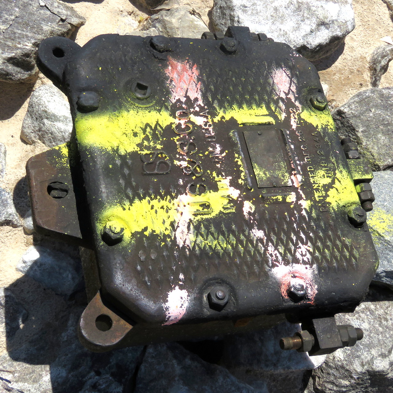
Here we see a Union Switch and Signal model impedance bond, patented in 1922. I am not sure if there were any earlier models of bond or if this was used on the 1915-1918 PRR and New Haven 25hz electrification projects before the patent was granted, but it would have been available for the major waves of electrification that took place in the 1920's and 30's. An impedance bond is a type of isolation transformer where traction return current can pass with low impedance (impedance is the AC version of resistance), while track circuit current faces high impedance and thus follows the path of least resistance through the track circuit logic. The necessary trick to making this work is to have track circuit current at a different frequency than the traction return current. For example DC traction current with an AC track circuit or one frequency of AC return current with another frequency of AC track circuit.
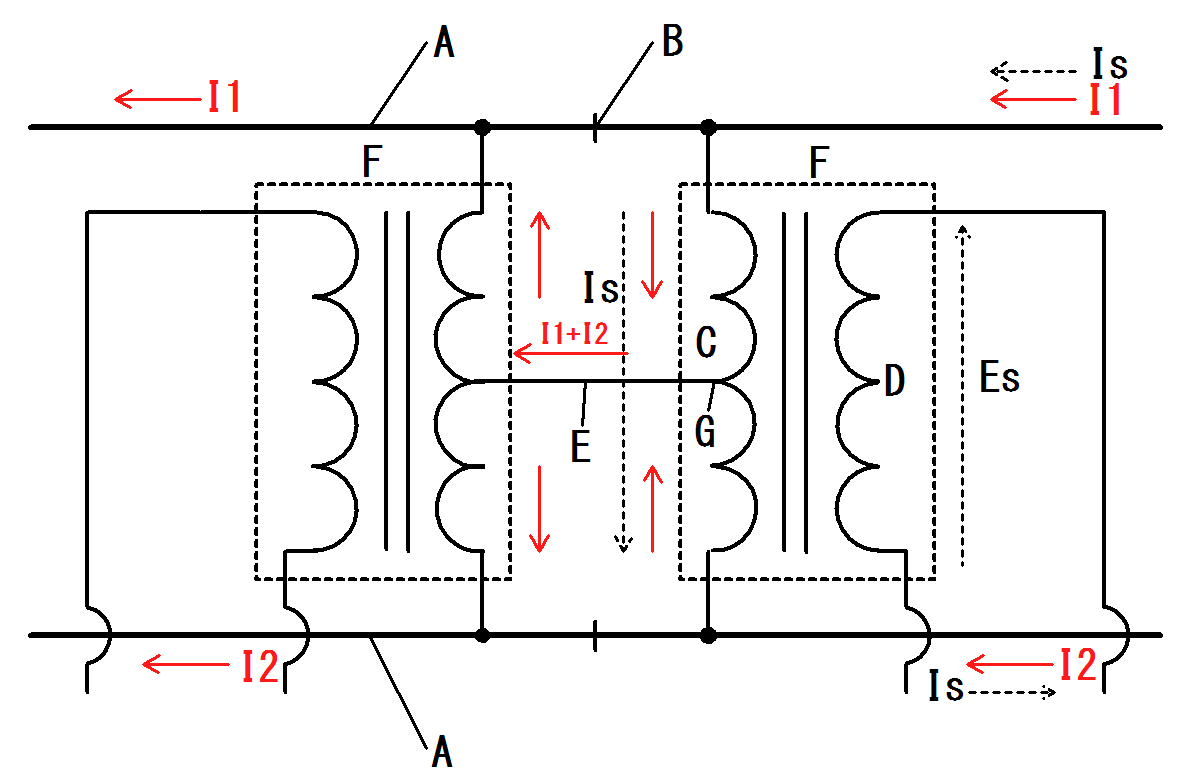
In the above diagram from a Japanese Wikipedia page we can see a slightly more elaborate setup for an impedance bond. The two coils connected at the center tap are what constitute the impedance bond. The secondary windings capture the AC track circuit current via the magic of induction and feed the signal logic. More typically the bond omits this secondary winding and the signal logic is fed directly from the rails. Remember this is a super high level summary so for more detailed technical information please consult Google or your reference library.
Here we see two of the 1922 patent US&S bonds and their modern Siemens replacements for use on Amtrak's NEC. Amtrak, like the PRR before it, uses 25hz traction power and 91.66hz coded AC track circuits. Normally the coded track circuits would operate at 100hz, but as a multiple of 25, return current harmonics could be detected as track circuit current, which is bad. 91.66hz is close enough to 100hz to be cross compatible with 100hz electronics.
The spec plate on the new bonds show the Amp rating for traction return current and the impedance values for 100hz current (400 ohms) and 60hz current (2.4 ohms). While 25hz isn't listed I am assuming that the value would be in an acceptable range. A DC traction system sees much higher amp loads than an AC system and therefore the bonds must be much larger with thicker windings to handle it. Systems with both AC and DC, like Penn Station, would use DC rated bonds.
Of course the story doesn't stop there. In the late 1960's the rail signaling industry introduced the concept of jointless track circuits for use in transit applications. These make use of AC frequencies in the "audio" range of 1-5 kHz. These higher frequencies attenuate after a much shorter distance and using a mix of frequencies one can have a given track circuit receiver able to hear the signal from a single specific transmitter. Still there is the issue of the pesky traction return current that needs to move between the rails, to ground and NOT into the signaling logic. The solution was the Wee-Zee bond (trademark of GRS) that creates this path to ground while preventing the track circuit signal passing between the two rails.
In this close up of a US&S "Minibond" on the Chicago El, we can see the the listed transmit-receive frequency pairs, the cab signal code frequency and the DC power rating (3000amps at 0.00003 ohm).
Now if you like Technology Connections, here's an interesting one for you that revolves around the necessity of impedance bonds. Europe is currently under the thrall of axle counters for train detection as opposed to track circuits. Why would the normally safety conscious Europe in interested in a train detection system that doesn't positively detect the presence of a train (or flood or broken rail)? Because the Central European 16.66Hz electrification club, which includes Germany, Austria, Switzerland and a few others, electrified their rail systems were those systems were still operated using non-track circuited manual block signaling. When upgrading to automatic block signaling, installing track circuits would require installation of impedance bonds and related electronics. Therefore an alternative, axle counters, was sought out and adopted.
Likewise, the NYC Subway is moving to Communications Based Train Control instead of the audio frequency track circuits as their use of the one rail system would require the installation of who knows how many Wee-Zee bonds. Just goes to show how technical decisions can be highly path dependent. Keep that in mind the next time you have trouble figuring our the logic behind that might not make complete sense.
![]() |
| The right hand rail is insulated at the track circuit block boundary, the left is not. |
Your first option is to use the one rail or 1+1 system. Here you have one rail with insulated joints creating track circuit blocks and the other rail acting as a common ground without insulated joints. One downside is that only the insulated rail gets broken rail protection. There are probably other downsides as well as this method was only used on some of the oldest electrified transit systems such as the NYC Subway. Another option is to have a 4th rail system like the London Underground where traction return current uses a dedicated 4th rail instead of the running rails. The better option is to use a device called an impedance bond to have both isolated track circuit blocks and a traction return path via the rails.
Here we see a Union Switch and Signal model impedance bond, patented in 1922. I am not sure if there were any earlier models of bond or if this was used on the 1915-1918 PRR and New Haven 25hz electrification projects before the patent was granted, but it would have been available for the major waves of electrification that took place in the 1920's and 30's. An impedance bond is a type of isolation transformer where traction return current can pass with low impedance (impedance is the AC version of resistance), while track circuit current faces high impedance and thus follows the path of least resistance through the track circuit logic. The necessary trick to making this work is to have track circuit current at a different frequency than the traction return current. For example DC traction current with an AC track circuit or one frequency of AC return current with another frequency of AC track circuit.
In the above diagram from a Japanese Wikipedia page we can see a slightly more elaborate setup for an impedance bond. The two coils connected at the center tap are what constitute the impedance bond. The secondary windings capture the AC track circuit current via the magic of induction and feed the signal logic. More typically the bond omits this secondary winding and the signal logic is fed directly from the rails. Remember this is a super high level summary so for more detailed technical information please consult Google or your reference library.
Here we see two of the 1922 patent US&S bonds and their modern Siemens replacements for use on Amtrak's NEC. Amtrak, like the PRR before it, uses 25hz traction power and 91.66hz coded AC track circuits. Normally the coded track circuits would operate at 100hz, but as a multiple of 25, return current harmonics could be detected as track circuit current, which is bad. 91.66hz is close enough to 100hz to be cross compatible with 100hz electronics.
The spec plate on the new bonds show the Amp rating for traction return current and the impedance values for 100hz current (400 ohms) and 60hz current (2.4 ohms). While 25hz isn't listed I am assuming that the value would be in an acceptable range. A DC traction system sees much higher amp loads than an AC system and therefore the bonds must be much larger with thicker windings to handle it. Systems with both AC and DC, like Penn Station, would use DC rated bonds.
Of course the story doesn't stop there. In the late 1960's the rail signaling industry introduced the concept of jointless track circuits for use in transit applications. These make use of AC frequencies in the "audio" range of 1-5 kHz. These higher frequencies attenuate after a much shorter distance and using a mix of frequencies one can have a given track circuit receiver able to hear the signal from a single specific transmitter. Still there is the issue of the pesky traction return current that needs to move between the rails, to ground and NOT into the signaling logic. The solution was the Wee-Zee bond (trademark of GRS) that creates this path to ground while preventing the track circuit signal passing between the two rails.
In this close up of a US&S "Minibond" on the Chicago El, we can see the the listed transmit-receive frequency pairs, the cab signal code frequency and the DC power rating (3000amps at 0.00003 ohm).
Now if you like Technology Connections, here's an interesting one for you that revolves around the necessity of impedance bonds. Europe is currently under the thrall of axle counters for train detection as opposed to track circuits. Why would the normally safety conscious Europe in interested in a train detection system that doesn't positively detect the presence of a train (or flood or broken rail)? Because the Central European 16.66Hz electrification club, which includes Germany, Austria, Switzerland and a few others, electrified their rail systems were those systems were still operated using non-track circuited manual block signaling. When upgrading to automatic block signaling, installing track circuits would require installation of impedance bonds and related electronics. Therefore an alternative, axle counters, was sought out and adopted.
Likewise, the NYC Subway is moving to Communications Based Train Control instead of the audio frequency track circuits as their use of the one rail system would require the installation of who knows how many Wee-Zee bonds. Just goes to show how technical decisions can be highly path dependent. Keep that in mind the next time you have trouble figuring our the logic behind that might not make complete sense.
Labels:
ABS,
Amtrak,
cab signals,
CBTC,
electrification,
GRS,
NYC Subway,
signaling,
track circuit,
US&S
Saturday, April 25, 2020
Amtrak Dual Equips Part of NEC for I-ETMS PTC System
Effective April 23rd, 2020, Amtrak is activating I-ETMS (Interoperable Electronic Train Management System) on its Philadelphia to Washington route between PENN and the end of CTEC territory at CP-AVENUE and on the Harrisburg Line between FRAZER and STATE. This is the PTC system generally used outside of the Northeast commuter zone by the Class 1's and other railroads and on Amtrak territory I-ETMS will be used by NS freights and MARC commuter trains. The bulletin order with the relevant information can be found here.
Here are some important takeaways regarding this bulletin order.
- I-ETMS relies on the cab signal system to enforce train separation as a CSS failure will constitute an I-ETMS failure. This was generally suspected to be the case due to the lack of I-ETMS antennas at intermediate signal locations in cab signal territory both on NS and on Amtrak.
"Trains operating with I-ETMS that experience a cab signal, ATC, Speed Control or LSL failure enroute must consider I-ETMS to be inoperative and proceed in accordance with SI 592-S2."
- Some MARC Locomotives were ACSES equipped for NEC operation, but as of 2018 MARC was still ACSES exempt. MARC now appears to be switching over to I-ETMS, but I am unsure if it is because the locomotives can only support one PTC system or simply want to simplify procedures as the Camden and Brunswick lines as CSX will use I-ETMS.

ACSES receiver on a MARC MP36 locomotive. - I am still working to get the instructions for the I-ETMS on board apparatus, but the I-ETMS special instructions make reference to time consuming software downloads, manual entry of consist weight and manual selection of track before entry into I-ETMS territory. All of this manual entry through what is probably a fairly simplistic interface device is likely what led to METRA's complaints about PTC setup times of 10-15 minutes necessitating schedule changes. ACSES does not require complex setup procedures due to the use of transponders.
- The rules state that the Stop release becomes available after 300 seconds (5 minutes) stopped within 1500 feet of a stop signal, but I was told that might be a typo as 30 seconds would be a more reasonable amount of time.
- It will be interesting to see how the two systems stack up regarding braking curves and calculated enforcement points.
- SEPTA's claims that ACSES was incompatible with I-ETMS to justify separating the West Trenton branch from the CSX Trenton line were not entirely truthful. The 2015/16 project cost a good deal of money and reduced capacity on the West Trenton Line with SEPTA claiming it was out of their hands. As I pointed out at the time there was nothing that would technically prevent deploying both systems on the same section of track and Amtrak has proven this assertion without much fuss or fanfare.
Tuesday, April 14, 2020
Photo Archive is Back (For Now)
I just wanted everyone to know that I used some of my corona virus time to get the remaining years of my photos archive back up where it can be accessed in an convenient manner. For those of you who don't know in 2017 I lost both of my conventional web hosts and was forced to fall back on Google for my photos and nothing for my other content. In 2019 Eric at RedOverYellow.Com was generous enough to provide some generic file storage and like I just managed to finish all of the re-uploading.
But wait, there's more! I am also in the process of fixing the dead links in this blog and have so far gotten up through 2014 (which is pretty good since the newer posts don't suffer from as many broken links ;-) ). Specifically this includes a lot of PDF documentation like employee timetables, builtin orders and rulebooks.
Please take note that due to some limitations on the hosting I have to eliminate most of the photo specific HTML landing pages. Also, due to a variety of reasons such as age or just me loosing the data, that some links simply cannot be restored. In these cases I will leave the links dead on the page just so people are aware that the information used to exist and now no longer does.
I am still looking for additional mirrors, especially from museums or long running institutions. I have leaned the hard way that the internet does not last forever, so the best I can do is try and find a home for my archive that can stand the test of time.
But wait, there's more! I am also in the process of fixing the dead links in this blog and have so far gotten up through 2014 (which is pretty good since the newer posts don't suffer from as many broken links ;-) ). Specifically this includes a lot of PDF documentation like employee timetables, builtin orders and rulebooks.
Please take note that due to some limitations on the hosting I have to eliminate most of the photo specific HTML landing pages. Also, due to a variety of reasons such as age or just me loosing the data, that some links simply cannot be restored. In these cases I will leave the links dead on the page just so people are aware that the information used to exist and now no longer does.
I am still looking for additional mirrors, especially from museums or long running institutions. I have leaned the hard way that the internet does not last forever, so the best I can do is try and find a home for my archive that can stand the test of time.
Tuesday, April 7, 2020
Surviving BNSF Marceline Sub Searchlights Retired
While this probably isn't breaking news I am still going to report the fact that the last two intact ATSF era signal bridges on the Marceline Sub in eastern Missouri were de-signaled in late 2019, some 6 years after the rest of the route was re-signaled in the summer of 2013. The two-track, weathering steel I-beam construction signal bridges at mileposts 243 and 241 not only remained standing, but also retained their US&S H-5 searchlights.
These signals were located between Argyle and Ortho and also retained their prefab concrete relay huts. As you can see from the above photos, PTC antennas had been erected and no replacement signals were on hand. However, seeing that the signal heads on the bridge at MP 238 had been turned in place, I just assumed that the MP 241 and MP 243 signals would likely be replaced or removed in short order. The replacement signals at MP 243 and MP 241 use 1 mast and one cabinet mounted half mast. The ATSF structures were still standing as of April 2020 and as far as i am aware the few color light equipped ATSF signal bridges are also still in place. My 2013 survey of this line segment can be found here.
![]() |
| MP 243 signal in 2013 |
![]() |
| MP 241 signal in 2013 |
Sunday, March 29, 2020
NYC Subway Signaling - A Decade of Change
Ten years ago I was provided with a amazing PDF document from the New York City Transit Authority that contained diagrams of every rail line, every rail yard and every interlocking on the Subway, Staten Island Railroad and even some railroad shotlines. The interlocking diagrams themselves had details from switch and signal numbers, details regarding the control panels and interlocking machines and even the date of details of the contracts that the signaling equipment was installed under.
Since then the NYCTA has been pushing hard to eliminate the last bastions of single interlocking towers with CTBC projects ongoing on the Flushing and Queens Boulevard Lines. As my document aged I attempted to get an updated copy, but was told that the NYCTA was annoyed that the first consolidated document had ever been created and that the information had been effectivly split up between all the various line managers. I don't know if that was true or not, the NYCTA culture thrives on control of information (often using "terrorism" as a justification), but while searching for some photos of the old E 180th St tower to fix a dead link I came upon a 2019 version of the same document.
Because nobody had metaphorically slipped me the new version "under the table" with a promise of confidentiality, I am just going to link both documents here so you all can see for yourself the extent of signaling heritage that has been lost on the NYCTA over the last ten years. Enjoy.
NYCTA Schematic Track and Interlocking Diagrams 2009
NYCTA Schematic Track and Interlocking Diagrams 2019
Since then the NYCTA has been pushing hard to eliminate the last bastions of single interlocking towers with CTBC projects ongoing on the Flushing and Queens Boulevard Lines. As my document aged I attempted to get an updated copy, but was told that the NYCTA was annoyed that the first consolidated document had ever been created and that the information had been effectivly split up between all the various line managers. I don't know if that was true or not, the NYCTA culture thrives on control of information (often using "terrorism" as a justification), but while searching for some photos of the old E 180th St tower to fix a dead link I came upon a 2019 version of the same document.
Because nobody had metaphorically slipped me the new version "under the table" with a promise of confidentiality, I am just going to link both documents here so you all can see for yourself the extent of signaling heritage that has been lost on the NYCTA over the last ten years. Enjoy.
NYCTA Schematic Track and Interlocking Diagrams 2009
NYCTA Schematic Track and Interlocking Diagrams 2019
Subscribe to:
Posts (Atom)