A blog devoted to explaining the ins and outs of North American railroad signaling, past, present and future. This blog seeks to preserve through photo documentation the great diversity and technical ingenuity of 20th century signaling and interlocking hardware and technology. Related topics cover interlocking towers and railroad communications infrastructure.
Note, due to a web hosting failure some of the photos and links may be unavailable.
There's a lot of work taking place on the former PRR Northeast Corridor these days and unfortunately it appears that the era of main line pneumatic point machines might be nearing an end. The stock of pneumatic interlockings had been dwindling for years with LANDOVER near Washington, DC, GRUNDY in Bristol, PA and FAIR in Trenton being the two latest to see wholesale conversion to electric US&S M3 style machines. Prior to that both THORN and PAOLI interlockings on the Harrisburg Line saw their pneumatics go even while their interlocking towers remained open.
Currently, what had been some of the best preserved main line pneumatic interlocking plants, RIVER and POINT at the north end of Baltimore's Bayview yard, are in the midst of an electric conversion as their turnouts are being replaced as part of a general maintenance project.
Unfortunately, due to their location, these two locations are difficult to photograph except from the rear of passing Amfleet equipped trains.
This will leave what is in my estimation only a single intact pneumatic main line interlocking plant, HOLMES, at Homesburg Jct in Philadelphia. OVERBROOK interlocking, with its staffed tower, is still largely pneumatic, but had seen select turnouts replaced with M3's.
Of course a significant number of terminal plants will remain pneumatic for the foreseeable future and one could possibly count terminal adjacent interlockings like Metra's TOWER A-2 and SEPTA's 16TH ST as Main Line as well, however neither see the high speed movements currently present at RIVER, POINT and HOLMES. The challenge for documentation is capturing the movement and sounds of the switches as they throw. At HOLMES this is most easily covered when local freights enter and exit the Buttleton branch, but this could also be achieved when tracks are out of service east or west of the plant. Of course the easiest way to engage with pneumatic point machines is to see them on rapid transit systems such as The PATH, NYC Subway and the SEPTA Broad Street Line.
Union Switch and Signal had always maintained a bit of a home field advantage around Pittsburgh, with the local railroads, most notably the PRR, preferring their products. As railroads grew larger, this hold field advantage grew smaller, mostly applying to the home town Port Authority Transit light rail Union Railroad. For example, both were some of the few customers of US&S's 80's pattern modular signals that were attempting to compete with Safetran's scallop shells.
Well, it appears that since the purchases by Ansaldo and more recently, Hitatchi, US&S has lost its local influence and the Union Railroad is now installing L&W brand signals from Missouri.
The URR was always a bit of a potpourri of signals, but the 80's US&S modular fare always stood out.
In southern Arizona one encounters the phenomena known as sky islands, where isolated mountain ranges, separated by harsh desert, become in effect islands for various plant and animal species due to the cooler temperatures and relative abundance of water. The Dragoon Mountains were one of these ecological islands that also happened to host an island of late model Southern Pacific signaling with short stature modular target signals. They had even survived the PTC asteroid with the familiar antennas installed to their original relay cabinets. This island was located on the double track section between VAIL XOVERS at Milepost 1000 and Dragoon Road at Milepost 1053. You can therefore imagine my dismay when I was passing the Sybil Road crossing at Milepost 1041.8 and saw a set of new Union Pacific LED signal masts.
Sybil Road 2016
Sybil Road 2024
The re-signaling took place between 2020 and the end of 2021. I suspect that Phoenix became so hot that the signal crews migrated to the cooler 4000 foot elevation of the Dragoon pass. In fact the riding temperatures of the southwest may have played a factor in shifting the signal locations nearer to road crossings. The Southern Pacific Milepost 1041 intermediates were actually a half mile to the west.
Sorry again for a late report, I just hadn't realized what had been lost until I was physically on site. The signal relocations and approach lighting so make the new signals more useful for railfanning train movements, however quite has been lost regarding the actual photo composition.
If there was a moment where I got into railroad signaling, it would be in the fall of 1998 when I quite literally got "into" railroad signaling. While being dropped off at South Jersey's Winslow Jct for the purpose of completing a 20 mile hike for a Boy Scout merit badge requirement, I noticed that one of the omnipresent plywood panels securing the lower level of WINSLOW tower had been removed. Scrambling inside I was presented with a trove of wonders that forever whet my appetite for the age of relay technology. I luckily had a 35mm film camera with me and was able to take a few photographs, but with my plan for the day already set, I only had about 10 minutes to get my fill. Although I had the motivation and opportunity to return, I as busy with school and kid stuff and by whatever time I did go back the tower had been re-secured.
For the next two decades I would periodically check up on the tower, waiting for locals to break back in so I could follow up with more photos. It was only in 2023 that I was provided with a do over and lets just say, things were quite different. While I've covered South Jersey's WINSLOW tower and the ghostly remains of the interlocking plant on this blog before, today we will explore the interior with two groups of my own photos photos taken 25 years apart, with some additional insights provided from a 2003 urbex visit and photos from when the tower was still in service.
If you are not familiar with WINSLOW (aka WINSLOW JCT), please check out my previous coverage to get a better idea of its history and layout. to summarize, WINSLOW was built in 1934 as part of the Pennsylvania-Reading Seashore Lines merger to PRR specifications with a brick tower, bay window and a US&S Model 14 electro-pneumatic interlocking plant. The tower was in service until 1983 when the NJDoT seashore services, run under contract by Conrail, were discontinued due to lower ridership and rapidly declining track conditions. The final service level consisted of 3 peak direction round trips to Atlantic City and 1-2 round trips to Ocean City and Cape May. When the tower closed the signals were turned and remained in place until Amtrak showed up to rebuild the line about 5 years later.
When I first got into WINSLOW it was about a decade into its second act as a radio repeater base for NJT operations on the line. A small lattice radio mast had been build against the north side of the tower and the upper story windows were still intact and letting in light. Towers serving in useful capacities as relay huts or crew bases is one of the more common factors behind their not getting demolished.
On the ground floor, the relay racks and associated relays had been removed, however the cabling that fed the US&S Model 14 interlocking machine on the operator's floor was largely still in place. From the look of it, one can see why so many old tower had their own regular maintainer that under the old system of inefficient railroad employment, could be in the position for many years.
When I visited in 1998 I don't remember much of anything in the ground floor, but in the 2003 urbex photo we can see that it was being used for general storage. I recall being informed by a Southern Railway of NJ employee mentioned that they had access to the tower, but I can't confirm if the items being stored were theirs or not.
There is a single flight of stairs along the rear wall connecting the relay room to the operator's floor. I could not tell if the relays were caged off or not as this was the typical practice to prevent operators from being tempted to tamper with the interlocking equipment to "fix" certain problems. In the 2003 photos we can see shelf style relays on the stairs, but I did not recall seeing any in 1998.
Heading up the single flight of stairs to the operator's level revealed something unexpected, a false wall built lengthwise across the room with a door in it.
The false wall had the unfortunate effect of blocking the view of the original PRR pattern model board, expect for a small bit at the top. I also managed to get a tight angle photo in from the side that came out pretty well all things considered.
The model board matches its final appearance from the mid-1960's through to 1983 where the main lines to Atlantic and Ocean cities were both single track manual block.
What really blew my mind back in the day was the presence of WINSLOW's 27 lever US&S Model 14 interlocking machine. Until this point I had never physically seen one or even known what one was. While some of my railroad books had contained pictures of specifically PRSL Model 14's, the fact that they didn't look like the classic armstrong type lever frame made it hard to intuit what that strange box thing in the photo was until I literally stumbled upon one and it all clicked, despite the lever cranks had all been removed.
Here is the WINSLOW machine as it appeared in service.
While NS's move to embrace cab signaling without fixed wayside signals (which I will refer to as Rule 562) on the former Conrail Pittsburgh Line was a big loss for the casual observation of railroad signaling in action, there remain a few points of interest between Harrisburg and Pittsburgh that I was able to identify during a journey on Amtrak's Pennsylvanian in 2023. If you find yourself railfanning in that corridor, you might want to check them out.
The first thing worth pointing out are the few remaining number plated intermediate signals that still exist along the line. There is one on the Main Line adjacent to CP-HOMER due to the retention of Rule 261 operation between CP-ANTIS and CP-ALTOONA. There are also a pair of autos on the Altoona Yard leads west of CP-ANTIS.
Another distant type automatic exists on the South Fork Secondary adjacent to the Main Line near CP-SO for trains approaching CP-W.
We've all seen the signed "signal indication points", but did you see the two different SIP's located right next to each other between CP-MO and CP-AR/UN near Gallitzin due to slight differences in the mileage chaining between the two alignments.
Also present are half size SIP huts like this one near CP-MARY in Marysville, PA that serves only a single track.
Of course when a SIP shares a relay hut with an interlocking why not sign them both like at CP-JW in Johnstown.
Finally we have the mystery of those places where full speed three headed interlocking signals are still present. When the Rule 562 operation went in, many back-to-back interlockings that supported signals like Medium Approach Medium (R/Y/G), saw their replacements only support Medium Clear (R/G) with the cab signal being held at Approach Medium.
However a few locations on the Pittsburgh Line retain full speed three headed masts. The first are obviously where trains might immediately exit Rule 562 territory such as at CP-ATOONA, CP-ANTIS, CP-ROCKVILLE and CP-BLOOM, or are not in Rule 562 territory at all (CP-WORKS).
However around Pittsburgh we also see three headed signals at CP-PITT and the former CP-EAST PITT. These might exist for the benefit of certain area short lines that might be able to run unequipped locomotives, or to provide better advance routing information for shortline and Passenger movements that need to use specific tracks and/or get off the Pittsburgh Line.
Anyway, keep all these locations in mind if you are looking for something a little bit extra signaling wise to capture in your photos.
In my last RBMN signaling update from a speeder video in the winter of 2022, I noticed that turned signals had appeared in the last gap of dark territory on their Main Line between Hometown, PA and JIM THORPE JCT near Mach Chunk. Well as of the Iron Horse rambles of Summer 2024 the gap has closed ever so slightly with the ABS now ending at the turned Milepos 118S intermediate and the formerly turned 118N intermediate now being an active distant signal for JIM THORPE JCT. Although I didn't get a photo of the 118N, the 118S now bears the "END AUTO BLOCK" sign.
Apart from this I noticed no additional signaling changes on the former Conrail Lehigh Line, although I just now realized that the RBMN built a brand new interlocking on the Lehigh Line between CP-DUPONT and CP-LAUREL HILL in order to place out of service a portion of the second main track there.
The "new" SEIDEL interlocking uses the same 1980's GRS type three lamp housing color light signals that are also in place at CP-DUPONT and some nearby intermediates. Likely in place for well over a decade now, I had always assumed it was a Conrail era interlocking.
Electrically locked switches are the red headed stepchildren of the interlocking world. Not nearly as glamorous as their powered brethren, and rarely ensconced within the safe confined of interlocking limits, electrically locked switches help make North America's efficient bi-directional main tracks possible. For the uninitiated let me clarify that while powered points are also "locked" by something involving "electricity", when I say electrically locked switch, I am referring to a hand throw switch that has some sort of electro-mechanical interlock that prevents operation in the face of an unsafe condition.. E-locked switch hardware is provided by both major North American signaling lineages (US&S and GRS) and in today's post I am going to provide a quick overview of the broad e-locked switch families and how they work.
In the beginning if a railroad didn't want the expense of interlocking a switch with signals via a staffed tower their choices were to assume the risk of trains not being able to get stopped by an improperly set hand throw switch or ensure that all hand throw switches were in the trailing configuration, something that required at least two single direction main tracks. As track circuiting became the norm, operating a hand throw switch could shunt the circuit like any other obstruction, but this wouldn't be much help if an approaching train had already passed the previous block signal.
Unprotected hand throw switch equipped with a track circuit interrupter.
The easiest solution is procedural control where the employee shunts the track circuit, waits a proscribed period of time, then throws the switch. However where the railroad desires a bit more assurance than a padlock and watch, the electric switch lock comes into play. The concept is simple, use a solenoid mechanism to prevent switch operation until allowed by the signaling system. This can include direct dispatcher/operator control, like from a lever on an interlocking machine, or conditions such as track circuit occupancy or a rundown timer. In general direct control is the less common of the two as within interlocking limits railroads tend to just pay a bit more for power operated switch machines.
US&S TM-20 switch stand without an electric lock.
At this point I want to take the time to clear up a misconception regarding electrically locked switches. Above is the US&S TM-20 hand throw switch stand. It kind of looks like a miniature point machine with wires going into it, a mechanism to work a pipeline connected derail and an extra locking bar. For years I thought this was an electrically locked point machine because it appears on main lines that tend to benefit from electrically locked points. However there is nothing in a TM-20 that provides for locking functionality. The cover on the end is just houses an integrated make/break circuit controller. So while this type of switch stand might look the part, the real e-lock is a bolt on component.
Abandoned GRS electric lock unit.
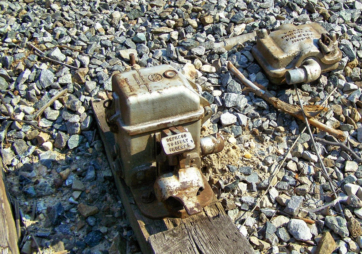
The E-Locks themselves come in two general forms, the plunger style and the pedal style. Each style is available from both vendor lines, but I want to discuss the pedal style first since it is the one paired with those TM-20 machines I just mentioned. The pedal style consists of a small box, separate from the hand throw point machine, which locks the hand throw switch arm in the desired position. The train crew's padlock holds down a small pedal. Removing the lock allowed the pedal to raise up, energizing the mechanism. In this state a small window displays either a green lamp if the switch is free to move or a red lamp if it is not. If a timer needs to be run, releasing the pedal starts it. Any timers and signaling relays are located in a trackside cabinet. When the lamp is green a second pedal can be depressed to unlatch the hand throw switch arm. Below is an example from the old CP-VO on the former Conrail Selkirk Branch where a direct control pedal type e-lock locks the throw arm of a basic dome type hand throw switch stand.
Interlocked e-lock hand throw switch stand within CP-VO.
Here we see a low profile US&S style lock device. Here we see a TM-20 with an SL-25 electric lock attached.
The SL-25 can be even located between the rails in a stand alone configuration and in this case uses a pipeline to lock two TM-20 point mechanisms on either end of an e-locked turnout.
Here we see the GRS answer to the TM-20 with an attached e-lock box. This example is located within the limits of CP-89 on the former Conrail Hudson Line and is released by a "lever" on the dispatcher's interface.
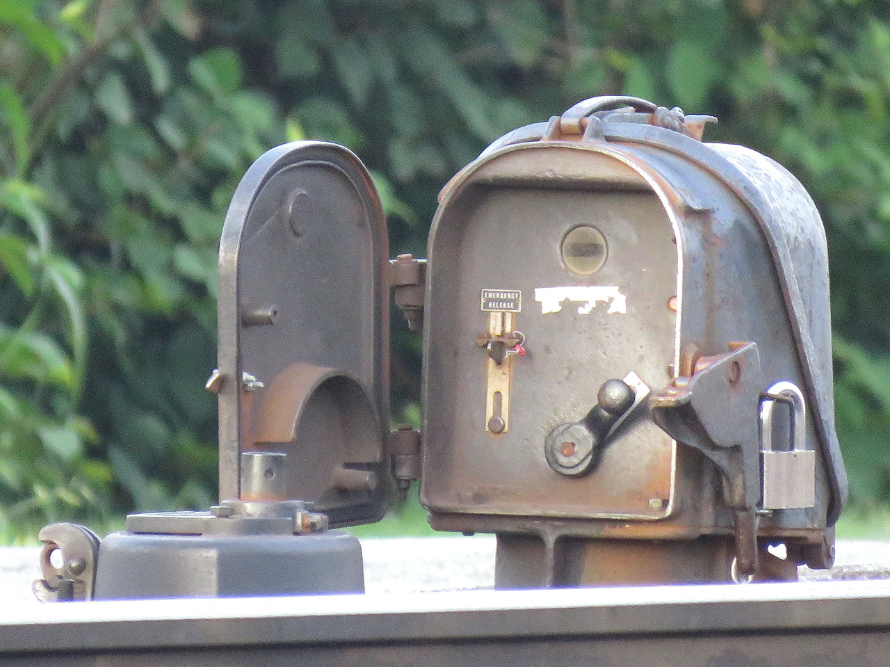
The plunger style is a bit more recognizable due to its more prominent form factor. The plunger lock consists of a little housing, sometimes on a raised pedestal, mounted adjacent to any type of hand throw switch stand. The trainman opens the little door and requests a release by moving a crank type lever from the lock to unlock-request position, similar to a US&S table interlocking machine. This engages the relays and timers in the cabinet and when conditions are safe, a solenoid releases and the crank is able to complete its travel, raising a metal plunger that is physically blocking movement of the switch point rodding in the process. The plunger is either directly below the housing or below the hollow pedestal, if present.
It is common to have both a short and long duration timer with short time (~30 seconds) applying when the main track is unoccupied and the long time (5-13min) applying when a main track train movement is possible. While short and long timers are not exclusive to the plunger type, the plunger type user interface makes them more apparent.
Another feature on the plunger type is the presence of a sealed emergency release button in case something goes wrong with the release logic. Breaking the seal and pressing the button allows for immediate release of the points. On the pedal type e-locks this functionality can be provided by an optional key switch.
Pedistal mounted plunger lock. Note the housing's similarity to a semaphore signal's.
These two types of e-locks are the bulk of what one will encounter in North America with the US&S and GRS equipment lines offering both form factors. It's actually pretty simple if you think about it, but if you don't want to take my word for it, here is a video from Mark Clay McGowan that describes the operation of each type in far more detail.
I hope you all found this interesting. I didn't get into the nitty gritty of identifying every exact model of lock, but now that you know what to look for, see if you can spot the slight differences out in the field.