This installment of Port Road Trips is going to be a short one between it includes only the two intermediate signal locations between WAGO interlocking, discussed in the last installment, and SHOCKS interlocking located at the junction of the Enola Branch and Royalton Branch. Unlike the automatic signals between WAGO and STELL which had been almost entirely replaced with NS type Darth Vader masts, the section between WAGO and SHOCKS exists as an island of PRR signaling with both locations getting a bit of a refresh when everything else was getting the color light treatment.
I will be showing off the signals with two sets of photos. The first are part of the larger Port Road tour collected in 2004 by a friend of the blog and shows what things looked like before the catenary poles were removed. The second group of photos were taken just recently in 2013. Unlike the signals north of WAGO these were not recently renumbered by NS as they were never seen as part of the Northern Central milepost system and reflect the distance to Parkesburg, PA.
The first of the two locations is the Milepost 45 automatics. Here in this 2004 view you can see the typical layout PRR PL automatics where there is a single catenary mast. One signal is mast mounted to the cat pole in the typical electric territory style. The other signal is mounted on a standard PRR ABS mast. Back in 2004 this section of the line still played host to an out of service 138kV 25Hz power circuit and an active 6000V 100Hz signal power circuit. Note the old school mast base/relay case next to the larger PRR relay box with the attached block phone.
The 495W ABS signal typically displays Approach for the Stop signal at WAGO, but back in 2004 it seemed that a train was en route as WAGO was pulled up enabling the 495W to display Clear. There is no lower head since WAGO does not provide for any non-Restricted speed diverging routes.
Somewhat backlit view of the 496E automatic displaying Clear with the catenary poles stretching off into the distance.
Getting to the MP 49 automatic did not require any sort of off road hiking as not only are they located adjacent to a small park road running along the Susquehanna River, but the Conrail C&S forces took the time to build this handy dandy little stairway up to them. Note the 6000V signal power supply. Each place the signal power was tapped the PRR provided a isolation switch in case there was some sort of line fault. Far above the PRR's 25Hz power supply is a modern day 3-phase 60Hz high voltage transmission line.
A blog devoted to explaining the ins and outs of North American railroad signaling, past, present and future. This blog seeks to preserve through photo documentation the great diversity and technical ingenuity of 20th century signaling and interlocking hardware and technology. Related topics cover interlocking towers and railroad communications infrastructure.
Note, due to a web hosting failure some of the photos and links may be unavailable.
Search This Blog
Friday, January 31, 2014
Sunday, January 26, 2014
Samsung Model 14
When dealing with 80-year old technology sometimes it might not be practical to make alterations using the same methods great grandfather would have. After technology is allowed to match on for decades or centuries the need for changee may result in strange mashups or hybrids. Thanks to its highly regulated nature railroad signaling is certainly no stranger to this phenomina where the best solution is often to touch as little as possible least you suddenly find yourself staring at millions of dollars in costs and extended downtime. Examples of this include use of LED lighting on mechanical semaphores or the remote servo-manipulation of mechanical levers, but today's example is a bit more audio-visual.
Recently CHURCH AVE interlocking on the New York City Subway's Prospect Park Line was re-signaled resulting in the retirement of the resident US&S Model 14 interlocking machine that was installed by the IND Subway System way back in 1933. The NYC Subway is home to a good number of surviving US&S and GRS electri-mechanical power interlocking machines and even when they are replaced the NYCTA has stuck by the use of all relay logic because why fool with what works and you can fix in house. In addition to the operators in the tower, platform dispatchers need to maintain a view of the line in order to manage headways and make platform announcements. In some cases the tower and dispatch office are co-located. Other times they are not. In those cases the dispatcher is provided with a mimic model board giving the same view as the towermen.Well for whatever reason the dispatch office at the west end of the outbound platform was never fitted with such a model board. In the years before CHURCH AVE tower (located at the east end of the outbound platform) was replaced, the Transit Authority came up with this novel solution to avoid having to graft a new model board on to the 1933 electronics.
Having trouble seeing what they did? Here is a closer look.
They pointed a CCTV camera at the 1933 vintage model board and then piped that into a Samsung flat screen monitor in the dispatch office. What can I say, it is certainly effective even if it is a bit of a kludge. If you went back in time and asked one of the original signal engineers if they thought this casual use of television would be more or less likely than let say...flying cars, I wonder what their answer would be. I mean even if such a thing were technically possible how could it ever cost less than just stringing several thousand feet of wire. I mean aren't workers cheap? Of course I also got some video of the model board in action.
If you are wondering why the model board doesn't seem to show all the trains properly it is because some of the track circuits (specifically those on the express tracks) have already been cut over.
Anyway if you would like some more examples of technological mashups here are a few more from the Syrian Civil War courtesy of Forgotten Weapons.
Recently CHURCH AVE interlocking on the New York City Subway's Prospect Park Line was re-signaled resulting in the retirement of the resident US&S Model 14 interlocking machine that was installed by the IND Subway System way back in 1933. The NYC Subway is home to a good number of surviving US&S and GRS electri-mechanical power interlocking machines and even when they are replaced the NYCTA has stuck by the use of all relay logic because why fool with what works and you can fix in house. In addition to the operators in the tower, platform dispatchers need to maintain a view of the line in order to manage headways and make platform announcements. In some cases the tower and dispatch office are co-located. Other times they are not. In those cases the dispatcher is provided with a mimic model board giving the same view as the towermen.Well for whatever reason the dispatch office at the west end of the outbound platform was never fitted with such a model board. In the years before CHURCH AVE tower (located at the east end of the outbound platform) was replaced, the Transit Authority came up with this novel solution to avoid having to graft a new model board on to the 1933 electronics.
If you are wondering why the model board doesn't seem to show all the trains properly it is because some of the track circuits (specifically those on the express tracks) have already been cut over.
Anyway if you would like some more examples of technological mashups here are a few more from the Syrian Civil War courtesy of Forgotten Weapons.
Monday, January 20, 2014
Call it the "Ohio CPL" and Petone Update
I believe I have mentioned this before but CSX is taking the "Baltimore" out of B&O CPL in its latest re-signaling project that will remove the last CPL signals from Baltimore City. These are located in the Bailey's Wye area and comprise CAMDEN, HB TOWER, BAILEY and LEADENTHALL ST interlockings. BAILEY is notable for its 3-track B&O CPL signal bridge and all of them were upgraded in the early 1990's in conjunction with the Camden Yards Sports Complex project. What a waste both in terms of hardware and cultural heritage.
The cutover is scheduled for President's Weekend so if you haven't gotten your photos already this is your last chance.
In other news BNSF dumping all the classic Northern Pacific searchlight signaling on the Cascades route between Seattle and Portland. This includes the popular cantilever masts in the Vancouver, WA area. Get your photos quickly. The Coast Starlight is probably the best option.
Finally, a friend of the blog in New Zealand went out and took some photos of the now closed Petone signalbox before it closed its doors for good. I have thus updated my short post about Petone with her work so thanks so much Sophisa.
![]() |
| Yes, that signal on the left is displaying Medium Approach Slow. |
Finally, a friend of the blog in New Zealand went out and took some photos of the now closed Petone signalbox before it closed its doors for good. I have thus updated my short post about Petone with her work so thanks so much Sophisa.
Sunday, January 12, 2014
North American Signaling Dialects
Signal aspect systems are a lot like languages. Many times they basically saying the same thing, but as you move around from place to place you might find those things spoken or pronounced in slightly different ways. In North America there is a fairly common language with single Green, Yellow and Red indicating Clear, Approach and Stop. There are common concepts like approach the next signal at some speed, or proceed at some speed through turnouts or proceed prepared to stop within half vision. In the coming year I will be taking a close look a all of the major signal aspect systems, noting their various strengths, weaknesses, quirks and similarities, but I wanted to start out highlighting some of the common patterns that separate one system from another.
*Y* Adopted By: NORAC (Conrail), CN, CP, IC, UP, UP, Caltrain
This is one of the more common distinctions in the Eastern half of the United States. Advance Approach informs the engineer to be prepared to stop at the second signal. It is used in short block situations (ie less than 2 miles at normal speeds) where a 3-block system using only Approach would not provide sufficient stopping distance. I'm sure I could look up the real history of how this dichotomy developed between using Y/Y and Flashing Yellow for Advance Approach, but I'm just going to turn this into a story between the New York Central, which was a Y/Y road and the PRR, which ultimately became a *Y* road, or at least its successors did.
The story wasn't originally between Y/Y and *Y* because flashing indications did not become popular until the 1950's. The real story is that Speed Signaled railroads always had the option to overload the Approach Medium indication for 4-block signaling. Instead of allowing the engineer the discretion to stop by the second signal the speed signaling method would enforce a 30mph restriction at the first signal. The Y/Y method, on the other hand, informed the engineer of congestion instead of making him guess if the problem was a diverging movement OR congestion (one reason that route signaled roads went for Y/Y if it was free). When flashing indications became available all the roads that had never bothered to deal with 4-block signaling or had just overloaded their Approach Medium signals adopted *Y* because it was both free and allowed blocks to be shortened without having to modify the wayside signal units.
Y/Y Advance Approach is one of those old-timey things that have somehow survived into the modern era. It was used back in the days of the semaphore by a few high density railroads that didn't want to overload Approach Medium and didn't want to constrain their engineers. Conrail had the oppurtunity to put it to bed with the formation of NORAC, but unfortunately CSX is a bit more hidebound and has been turning back the clock when re-signaling former Conrail territories.
Y/Y Adopted By:West of Mississippi
Approach "Diverging' signals, either speed or route, are those that instruct the engineer to approach the next signal at a proscribed speed in order to safely take a diverging route. This is an interesting East vs West thing I don't really know where it came from, although I suspect lower quadrant semaphores had a role to play. The east almost universally uses Y/G to instruct engineers that they are about to diverge, while out West Y/Y is the standard. Canada beaks the tie with Y/G, but it still makes me wonder why the western roads wanted to be different. Like I said I suspect it has something to do with lower quadrant semaphores as Y./G is actually severely under utilized in the west, having only been recently resurrected for Approach Limited type indications.
Y/Y Adopted By: PRR, Caltrain, Amtrak, B&M (Guilford), Conrail, Canada
Here is a Speed Signaling special that certainly doesn't apply anywhere out west as all those guys use Y/Y for Approach Diverging. Another interesting point here is that sensible signal aspect systems like NORAC allow bot BOTH versions of Approach Slow, yet member railroads show distinct preferences for which they tend to adopt. Approach Slow is exactly what it says on the tin. Y/Y is an obvious choice because if Y/G is Approach Medium, downgrading the lower head to Y reduces the speed to Approach Slow. Of course Y/R/G is also an obvious choice since Y/G/R is Approach medium and moving the Green to the lower head downgrades it to slow. Y/R/G is the position theory version and Y/Y the color theory version. For roads that already adopted Y/Y for Advance Approach Y/R/G is what you are left with. Unfortunately this requires the use of so called "three headed monsters" and also precludes Approach Slow from being displayed on dwarfs.
Looking back at NORAC which employs both methods it is interesting to see which member roads choose to use which signal. Conrail generally went with Y/Y once it standardized system wide in the 1990's. Amtrak has also been a big user of Y/Y. On the other hand NJT has made frequent use of Y/R/G as has SEPTA.
Y/R/*G* Adopted By: Seaboard, CSX, NYC, Reading,C&O
Typically trains run on the model of prepare to diverge, diverge, proceed. However when where finf a situation where one needs to diverge, then immediately diverge again you need a special "combination" signal that provides explicit speed/route instruction for the first action and then the next. Now, the majority of railroads have tended to eschew these sorts of signals, either providing interlocking exit signals or allowing trains to diverge over a signal where the immediate action is implied from the preceding signal or over restricts the train for the next signal (think Medium Approach instead of Medium Approach Medium).
Anyway, one of the strangest splits in signaling practice is the use of R/Y/G for Medium Approach Medium vs Medium Approach Slow. With CSX and the former New York Central on board with the Medium Approach Slow it would seem that that is the standard, however it is somewhat baffling why those railroads would have so many situations where one encounters a medium speed route right before a slow speed route. Slow speed switches are actually pretty rare so why were those roads installing them enough to make Medium Approach Slow so necessary? Well the answer is that sidings would have single dwarf signals at their exit points. While the turnout might be Medium Speed, they would be signaled at Slow Speed, hence the need for Medium Approach Slow. In fact the New York Central didn't even have a Medium Clear dwarf indication. As time passed and better siding exit signals were provided Medium Approach Medium was created by using the flashing indication.
When Conrail and the other Northeast roads created NORAC this anachronism was thrown out and R/Y/G was given over to the now more common Medium Approach Medium. In fact Conrail didn't even bother to adopt any Medium Approach Slow indication. Where sidings were equipped with slow speed exit signals they were upgraded to show Medium Clear using G/*R* from G/R Slow Clear. Again, the reversion of R/Y/G M-A-M to R/Y/*G* on former Conrail territory being changed to Seaboard signaling can be considered a step backwards on CSX's part.
R/*Y*/R Adopted By: Southern, N&W, DRG&W, BNSF
This is the same issue as above only as seen in route signaled systems. One would assume that R/Y/Y would be the default seeing as how Y/Y is the standard Approach Diverging indication. However R/Y/Y requires three heads and when one is upgrading a Restricted Speed siding into a signaled siding it would be nice to not have to modify the two headed searchlight with a lower head that can display Y, R or L. The easy solution for signal engineers in the 1950's with newly reliable flashing relays was to use R/Y for Diverging Approach and R/*Y* for Diverging Approach Diverging.
This has resulted in R/*Y* (or R/*Y*/R) becoming more popular than R/Y/Y. In the east the N&W adopted it with the Southern adopting a variation for use with slow speed entry and exit signals. Out west the R/Y/Y is the official indication for UP system wide, but most of the former DRG&W territory uses R/*Y* via special instruction. BNSF actually uses both although they are given different names with R/Y/Y being Diverging Approach Diverging and R/*Y* Diverging Approach Medium. R/*Y* is more popular due to the needs for only two signal heads
One expects rare signal indications to require three heads. Approach Slow, Medium Approach Medium and the like aren't the sorts of signals one will see displayed every day. However quite a large number of railroads adopted systems that only allowed Medium Approach to be displayed on three headed masts. to be fair there was a time when almost all home signals were expected to have three places, if for no other reason than to allow for the use of a subsidiary semaphore in the bottom position to display R/R/Y Restricting, but quite a few railroads allowed this practice to persist well into the modern era.
The PRR had a unique situation wherein it completely lacked a Medium Approach, preferring trains to diverge over Approach, but adopted one in the 1950's when flashing relays became more available. This was carried over into Conrail and NORAC with the R/*Y* indication for use on two headed masts. Still, NORAC is the only system to adopt R/*Y* Medium Approach with others sticking with three headed masts or R/Y if that is not otherwise occupied by Restricting. Interestingly enough CSX uses R/Y/R in territories slated for conversion to Seaboard signaling in the future, but needing NORAC signaling in the present as it is common to both systems.
R/R/Y Adopted By: Southern, Reading, FEC
For concept so common in North American signaling I don't know of anything else with more options to be expressed. From number plates to marker lights to flashing read and lunar white it seems that every railroad had a different way of telling trains to move slowly and not crash into stuff. One of the most interesting distinctions is between railroads that allow R/Y Restricting and Railroads that only allow R/R/Y Restricting. I term these two 'lower yellow Restricting" and "bottom yellow Restricting".
R/R/Y restricting originally came about from very early interlocking technology where the Restricting indication would be controlled via its own lever or would utilize some different system to display since a Restricting was what one would pull up when the signal would not display normally. The early R/R/Y often involved a smaller semaphore flag or ground mounted semaphore called a subsidiary or call-on signal that would only be pulled up when the train was standing at the Stop. If the subsidiary signal was not needed at a particular location the railroad would have the choice of just providing a red marker or just assuming the crew could tell a main signal from a subsidiary signal and then allow R/Y to be used for something else.
If the second head wasn't present you would have one main signal with one subsidiary far down on the post.This ultimately resulted in the bottom yellow form of Restricting where two headed signals need a gap between the heads to change a Diverging Approach into Restricting.
Railroad not using subsidiary signals or not using them exclusively would then have the choice of using R/Y for Restricting, but that would then limit Medium Approach to a signal with three heads (see above) or simply not employing that particular indication. Until NORAC and its option of R/*Y* this was the choice that railroads faced, two head Medium Approach and three head Restricting or three head Medium Approach and two head Restricting.
L or *R* Adopted By: Most Western Roads, Seaboard, B&O, PRR
The final piece of signaling dialect I plan to tackle today is the age old argument between making Restricting the old man out with a strange color or having to flash or by making something else the odd man out by giving Restricting a yellow slot on the lowest head. Incidentally all of the position light systems, ie the PRR, B&O and N&W, all count as being in the second camp as their forward slash would count as lunar in a color light system. This is of course clear on B&O and Amtrak where that slash is also colorized lunar.
Not counting position lit systems non-yellow Restricting is most popular out west with Lunar being the previous standard that has now been supplanted with *R* as they avoids the need for second or third heads at absolute signals. The only exception is CSX whose Seaboard system made exclusive use of Lunar. The Seaboard made use of Lunar very sparingly, usually only where trains would need to enter a yard, but with CSX's expanded use we are seeing quite a few 4-lamped signal heads. Again with all its recent re-signaling CSX seems to have passed up an opportunity to adopt *R* and eliminate yet another of its signaling kludges.
Anyway, I could go on and on with this sort of thing, but these are the major ones and I will be referring to them as i explore the various signal indication systems used in North American in my upcoming series Better Know a Signaling System.
Y/Y vs *Y* Advance Approach
Y/Y Adopted By: Seaboard, CSX, New York Central, New Haven, Southern, N&W, Reading*Y* Adopted By: NORAC (Conrail), CN, CP, IC, UP, UP, Caltrain
This is one of the more common distinctions in the Eastern half of the United States. Advance Approach informs the engineer to be prepared to stop at the second signal. It is used in short block situations (ie less than 2 miles at normal speeds) where a 3-block system using only Approach would not provide sufficient stopping distance. I'm sure I could look up the real history of how this dichotomy developed between using Y/Y and Flashing Yellow for Advance Approach, but I'm just going to turn this into a story between the New York Central, which was a Y/Y road and the PRR, which ultimately became a *Y* road, or at least its successors did.
![]() |
| You really needed a second head for that? This ain't semaphores. |
Y/Y Advance Approach is one of those old-timey things that have somehow survived into the modern era. It was used back in the days of the semaphore by a few high density railroads that didn't want to overload Approach Medium and didn't want to constrain their engineers. Conrail had the oppurtunity to put it to bed with the formation of NORAC, but unfortunately CSX is a bit more hidebound and has been turning back the clock when re-signaling former Conrail territories.
Y/Y vs Y/G Approach "Diverging"
Y/G Adopted By: East of Mississippi and CanadaY/Y Adopted By:West of Mississippi
Approach "Diverging' signals, either speed or route, are those that instruct the engineer to approach the next signal at a proscribed speed in order to safely take a diverging route. This is an interesting East vs West thing I don't really know where it came from, although I suspect lower quadrant semaphores had a role to play. The east almost universally uses Y/G to instruct engineers that they are about to diverge, while out West Y/Y is the standard. Canada beaks the tie with Y/G, but it still makes me wonder why the western roads wanted to be different. Like I said I suspect it has something to do with lower quadrant semaphores as Y./G is actually severely under utilized in the west, having only been recently resurrected for Approach Limited type indications.
![]() |
| Route signaling, but Yellow over Green still means diverge. |
Y/Y vs Y/R/G Approach Slow
Y/R/G Adopted By: New York Central, Seaboard, Reading, NJT,Y/Y Adopted By: PRR, Caltrain, Amtrak, B&M (Guilford), Conrail, Canada
Here is a Speed Signaling special that certainly doesn't apply anywhere out west as all those guys use Y/Y for Approach Diverging. Another interesting point here is that sensible signal aspect systems like NORAC allow bot BOTH versions of Approach Slow, yet member railroads show distinct preferences for which they tend to adopt. Approach Slow is exactly what it says on the tin. Y/Y is an obvious choice because if Y/G is Approach Medium, downgrading the lower head to Y reduces the speed to Approach Slow. Of course Y/R/G is also an obvious choice since Y/G/R is Approach medium and moving the Green to the lower head downgrades it to slow. Y/R/G is the position theory version and Y/Y the color theory version. For roads that already adopted Y/Y for Advance Approach Y/R/G is what you are left with. Unfortunately this requires the use of so called "three headed monsters" and also precludes Approach Slow from being displayed on dwarfs.
![]() |
| Whole lot of slashes going on. |
R/Y/G vs R/Y/*G* Medium/Approach Medium
Y/R/G Adopted By: NORAC, D&H, NS,Caltrain, B&MY/R/*G* Adopted By: Seaboard, CSX, NYC, Reading,C&O
Typically trains run on the model of prepare to diverge, diverge, proceed. However when where finf a situation where one needs to diverge, then immediately diverge again you need a special "combination" signal that provides explicit speed/route instruction for the first action and then the next. Now, the majority of railroads have tended to eschew these sorts of signals, either providing interlocking exit signals or allowing trains to diverge over a signal where the immediate action is implied from the preceding signal or over restricts the train for the next signal (think Medium Approach instead of Medium Approach Medium).
![]() |
| I like to call this one "The Christmas Tree" |
When Conrail and the other Northeast roads created NORAC this anachronism was thrown out and R/Y/G was given over to the now more common Medium Approach Medium. In fact Conrail didn't even bother to adopt any Medium Approach Slow indication. Where sidings were equipped with slow speed exit signals they were upgraded to show Medium Clear using G/*R* from G/R Slow Clear. Again, the reversion of R/Y/G M-A-M to R/Y/*G* on former Conrail territory being changed to Seaboard signaling can be considered a step backwards on CSX's part.
R/Y/Y vs R/*Y*/(R) Diverging Approach Diverging
R/Y/Y Adopted By: UP, BNSFR/*Y*/R Adopted By: Southern, N&W, DRG&W, BNSF
This is the same issue as above only as seen in route signaled systems. One would assume that R/Y/Y would be the default seeing as how Y/Y is the standard Approach Diverging indication. However R/Y/Y requires three heads and when one is upgrading a Restricted Speed siding into a signaled siding it would be nice to not have to modify the two headed searchlight with a lower head that can display Y, R or L. The easy solution for signal engineers in the 1950's with newly reliable flashing relays was to use R/Y for Diverging Approach and R/*Y* for Diverging Approach Diverging.
R/Y/R Medium Approach
R/Y/R Only Adopted By: NYC, Reading, D&H, N&W, Canada, B&MOne expects rare signal indications to require three heads. Approach Slow, Medium Approach Medium and the like aren't the sorts of signals one will see displayed every day. However quite a large number of railroads adopted systems that only allowed Medium Approach to be displayed on three headed masts. to be fair there was a time when almost all home signals were expected to have three places, if for no other reason than to allow for the use of a subsidiary semaphore in the bottom position to display R/R/Y Restricting, but quite a few railroads allowed this practice to persist well into the modern era.
![]() |
| No flashing needed on three headed signals. |
R/Y vs R/R/Y Restricting
R/Y Adopted By: NYC, NORAC, C&O, N&W, EJE, RF&P, CanadaR/R/Y Adopted By: Southern, Reading, FEC
For concept so common in North American signaling I don't know of anything else with more options to be expressed. From number plates to marker lights to flashing read and lunar white it seems that every railroad had a different way of telling trains to move slowly and not crash into stuff. One of the most interesting distinctions is between railroads that allow R/Y Restricting and Railroads that only allow R/R/Y Restricting. I term these two 'lower yellow Restricting" and "bottom yellow Restricting".
R/R/Y restricting originally came about from very early interlocking technology where the Restricting indication would be controlled via its own lever or would utilize some different system to display since a Restricting was what one would pull up when the signal would not display normally. The early R/R/Y often involved a smaller semaphore flag or ground mounted semaphore called a subsidiary or call-on signal that would only be pulled up when the train was standing at the Stop. If the subsidiary signal was not needed at a particular location the railroad would have the choice of just providing a red marker or just assuming the crew could tell a main signal from a subsidiary signal and then allow R/Y to be used for something else.
![]() |
| That oddly shaped lower head is the last vestige of the "subsidiary" signal. |
If the second head wasn't present you would have one main signal with one subsidiary far down on the post.This ultimately resulted in the bottom yellow form of Restricting where two headed signals need a gap between the heads to change a Diverging Approach into Restricting.
| Mind the gap. |
Y vs L or *R* Restricting
R/Y or R/R/Y Adopted By: Most Eastern Roads, C&O, CanadaL or *R* Adopted By: Most Western Roads, Seaboard, B&O, PRR
The final piece of signaling dialect I plan to tackle today is the age old argument between making Restricting the old man out with a strange color or having to flash or by making something else the odd man out by giving Restricting a yellow slot on the lowest head. Incidentally all of the position light systems, ie the PRR, B&O and N&W, all count as being in the second camp as their forward slash would count as lunar in a color light system. This is of course clear on B&O and Amtrak where that slash is also colorized lunar.
![]() |
| Thanks Seaboard Coast Line, you just had to be different. |
Anyway, I could go on and on with this sort of thing, but these are the major ones and I will be referring to them as i explore the various signal indication systems used in North American in my upcoming series Better Know a Signaling System.
Tuesday, December 31, 2013
Heya Toots! - The Story of the Interlocking Horn
Anyone who has spent time in towers or gotten up close looks at CTC consoles or video displays may have noticed the presence of buttons (or icons) labeled horn or whistle or emergency horn. Occupying the same general category of ancillary functions as point heaters, maintainer call lights and low air alarms the "Interlocking Horn" is a vestige of a time long past when communication was intermittent and unidirectional, but still serves a purpose to this day.
The concept of an interlocking horn is pretty simple and basically serves as a method for the dispatcher or operator controlling the interlocking to communicate with train crews or other personnel who might happen to be in the area. As you may have already surmised the use of binary state sound generators to transmit information have been generally supplanted by radios and mobile phones, but interlocking horns can still be found mounted on present day relay huts installed up through the current day (2014).
I first learned of interlocking horns in a discussion of Pennsylvania Railroad block operation where they were described as being used to stop trains in an emergency if the operator became aware of an unsafe condition, but the train had already passed the controlling signal. The operator would sound the horn and upon hearing it either the locomotive crew or (more likely) the rear end crew would bring the train to an immediate stop and use a line side telephone to communicate with the tower operator. The practice always sounded a bit dodgy to me as trains are a loud place to work and unlike a visual signal it is a bit harder to verify that an alertness signal is not being sounded. Still, horns can be made very loud and with 2 or 3 people riding in the caboose it was likely that at least somebody would catch the signal that the bridge ahead was out. Still, a quick glance through the current NORAC rulebook shows that interlocking horns are a bit more complicated than that with a vocabulary that approximates the old trainline communication whistle system that was ultimately supplanted by crew radios. Here is the exact text of NORAC rule 18.
Naturally the Pennsylvania Railroad made frequent use of interlocking horns due to their embrace of and electro-pneumatic interlocking plants. With a source of compressed air on hand, it was trivial to attach a horn to the side of the tower and then run a wire to a button inside. Due to the length of some interlockings one horn would not be sufficient to provide warning at both ends so multiple horns were used with one being placed on the tower and others being mounted to remote air compressors or other air handling equipment.
Horn buttons in towers could be mounted on their own as seen in OVERBROOK, but often times they were placed on a panel with numerous other buttons for lights or communications or special interlocking functions.
The most common horn configuration makes use of two bells, one pointed in each direction to provide maximum coverage. Usually the horn bells are symmetrical, but there are some examples of the horns being asymmetric.
The most amazing thing is that the concept of the interlocking horn outlasted the interlocking tower era itself. Like point heaters and maintainer call lights interlocking horns were mounted on CTC era relay huts and hooked up to the code line for dispatchers to sound remotely. Still, this isn't entirely surprising seeing that portable radios were not reliable until the 1980's and dispatchers still needed a way to get MoW crews in the area of a relay hut to phone home. Where electrically operated switch machines removed the need for an on site compressed air plant, "klaxon" type electric horns were employed. As you can see with this example at NORGE interlocking on the CSX Peninsula Sub the small single bell was clearly intended to communicate with trackside workers and not the train crew.
Unfortunately as these and other 1970's era CTC relay houses are being replaced the new CSX standard hut does not provide for the continued employment of interlocking horns. Even in the 1970's use of interlocking horns was not uniform as can be seen with LEE HALL interlocking being provided with an slender truck style horn while only two miles away WEST LEE HALL was not provided with one at all.
As technology marched on so did the design and employment of the horns used at interlocking. In fact some could barely be considered horns at all like this loudspeaker device mounted to the relay hut of LEADENHALL ST interlocking in downtown Baltimore, MD.
Interlocking horns were not just the purview of the PRR or former Chessie system lines. Here we see a relay hut at CPO-4 on the D&H Colonie Sub which had been recycled from CPF-130 on the Freight Main Line sporting a small, 100% external klaxon type unit.
New Jersey Transit is perhaps one of the last believers in the concept of the interlocking horn. Here is a 2003 photo taken of the recently installed ATLANTIC interlocking relay hut in Atlantic City New Jersey with a compact twin bell unit mounted squarely on the side.
A decade later we see that NJT is still at it with a similar unit installed on the side of the brand new (2013) DIVIDE interlocking in Pennsauken, NJ. A similar horn was applied to the new JORDAN interlocking two miles to the east.
I am sure if I scoured my records thoroughly enough I could find other examples of interlocking horns on other railroads, but I am pretty sure you get the point. The takeaway is that the next time you are out shooting some classic signal, make sure you get a nice closeup of that odd looking horn on the side of the relay house. They are yet another disappearing vestige of our signaling and communications past.
The concept of an interlocking horn is pretty simple and basically serves as a method for the dispatcher or operator controlling the interlocking to communicate with train crews or other personnel who might happen to be in the area. As you may have already surmised the use of binary state sound generators to transmit information have been generally supplanted by radios and mobile phones, but interlocking horns can still be found mounted on present day relay huts installed up through the current day (2014).
I first learned of interlocking horns in a discussion of Pennsylvania Railroad block operation where they were described as being used to stop trains in an emergency if the operator became aware of an unsafe condition, but the train had already passed the controlling signal. The operator would sound the horn and upon hearing it either the locomotive crew or (more likely) the rear end crew would bring the train to an immediate stop and use a line side telephone to communicate with the tower operator. The practice always sounded a bit dodgy to me as trains are a loud place to work and unlike a visual signal it is a bit harder to verify that an alertness signal is not being sounded. Still, horns can be made very loud and with 2 or 3 people riding in the caboose it was likely that at least somebody would catch the signal that the bridge ahead was out. Still, a quick glance through the current NORAC rulebook shows that interlocking horns are a bit more complicated than that with a vocabulary that approximates the old trainline communication whistle system that was ultimately supplanted by crew radios. Here is the exact text of NORAC rule 18.
18. Horn Signals Used by Dispatchers or OperatorsLong story short the interlocking horn was intended to stop train movements or get some sort of wayside employee to call the dispatcher or operator. In my discussions with current operators and dispatchers I have found that in modern times the horns are rarely used in this capacity. More often than not they are used to scare children or other trespassers off the tracks or perhaps to warn nearby employees of approaching train movements although in those situations a full time whistle/safety man is often on had to do the job.
The following are horn signals that may be used by Dispatchers or Operators at interlockings or other designated points. The signals are illustrated by “o” for short sounds and “—” for long sounds.
SOUND INDICATION
(a) — All movements within interlocking limits must stop immediately.
(b) o o Normal movement may be resumed after receiving the proper signal or permission of Operator.
(c) o o o Whistle or Horn test.
(d) o o o o Signal maintainer must call the Dispatcher or Operator.
(e) o o o o o Electric traction employee must call the Dispatcher or Operator.
(f) o o o o o o Trackman must call the Dispatcher or Operator.
(g) A bell, horn, white light or oscillating white light at remotely controlled signals and interlockings indicates that any employee, except on moving trains, must immediately communicate with the Dispatcher or Operator.
Horn buttons in towers could be mounted on their own as seen in OVERBROOK, but often times they were placed on a panel with numerous other buttons for lights or communications or special interlocking functions.
![]() |
| Insect infestation is a problem in Tidewater Virginia. |
Unfortunately as these and other 1970's era CTC relay houses are being replaced the new CSX standard hut does not provide for the continued employment of interlocking horns. Even in the 1970's use of interlocking horns was not uniform as can be seen with LEE HALL interlocking being provided with an slender truck style horn while only two miles away WEST LEE HALL was not provided with one at all.
![]() |
| Truck horn and exposed cloth and tar insulated wire bundles. Classy. |
As technology marched on so did the design and employment of the horns used at interlocking. In fact some could barely be considered horns at all like this loudspeaker device mounted to the relay hut of LEADENHALL ST interlocking in downtown Baltimore, MD.
![]() |
| NJT is also committed to the lineside telephone box. |
| Yes, that is a new relay hut design. |
Labels:
CSX,
DnH,
interlocking,
interlocking tower,
NJT,
PRR
Tuesday, December 24, 2013
PHOTOS Port Road Trips - WAGO Interlocking
In our third episode of Port Road Trips we will examine the Conrail era WAGO interlocking which replaced the older CLY interlocking as the southern endpoint of the Northern Central Main Line / Enola Branch parallel running configuration. The replacement of CLY was motivated by the general redundancy of the NCRR line and the replacement of the 2x2 configuration with a single 2-track ABS line running on the Enola Branch alignment. While the NCRR no longer ran through to Baltimore, there was still local freight traffic to York and other points in the vicinity so a new interlocking was constructed closer to where the Enola Branch and NCRR lines originally met at Wago Junction Here is how this section of the line appeared in the 1998 Conrail Employee Timetable. Note that as sometimes happened on Rule 251 ABS lines the interlockings were not prefixed with CP. I don't know why that was, but for the purposes of this writeup I will follow the same practice.
For a more detailed view of WAGO interlocking here is an interlocking chart dating from 1997. There are a number of differences between this chart, the 1998 timetable and the facts on the ground in 2012 and I will get into them as we move through the interlocking. All of the differences are of the "stuff being removed" variety" so the chart has everything that was ever part of the plant.
The changes involved in the switch from WAGO to CLY actually begin between the two points with a Block Limit Station named GOLD being established at MP 56. This was installed to allow trains requiring needing to move eastward at WAGO to pull out onto the main line and then reverse. With GOLD the dispatcher would not have to hold the track all the way to STELL or use a less precise milepost "station" on the Form D. GOLD was located just east of the NCRR MP 72 automatic.
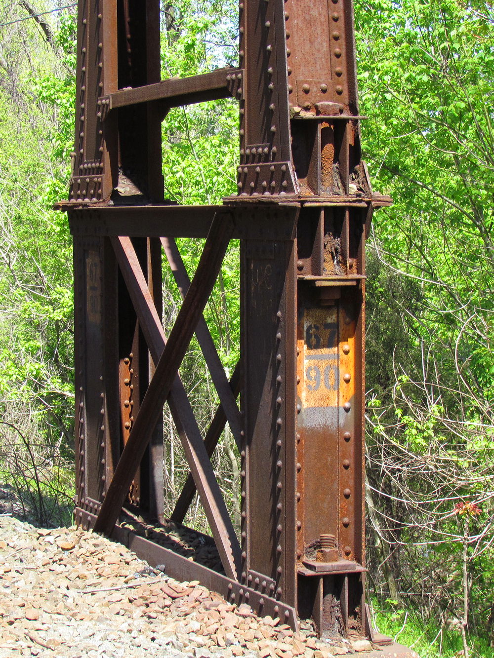
WAGO interlocking was typical for 1980's Conrail interlockings, making use of existing signaling arrangements as much as possible. In this case the new interlocking was situated at NCRR milepost 67 ABS signaling location south of CLY which allowed reuse of the old PRR signal bridge. Like the other 4-track ABS signal bridges on the 2+2 section this one was elevated on risers (note the old milepost) to clear the overhead catenary when they were installed in the late 1930's and due to the NS re-signaling this is probably the only surviving bridge of this type. Note the disused mounting for the westbound Enola Branch ABS signal at the right of the gantry.
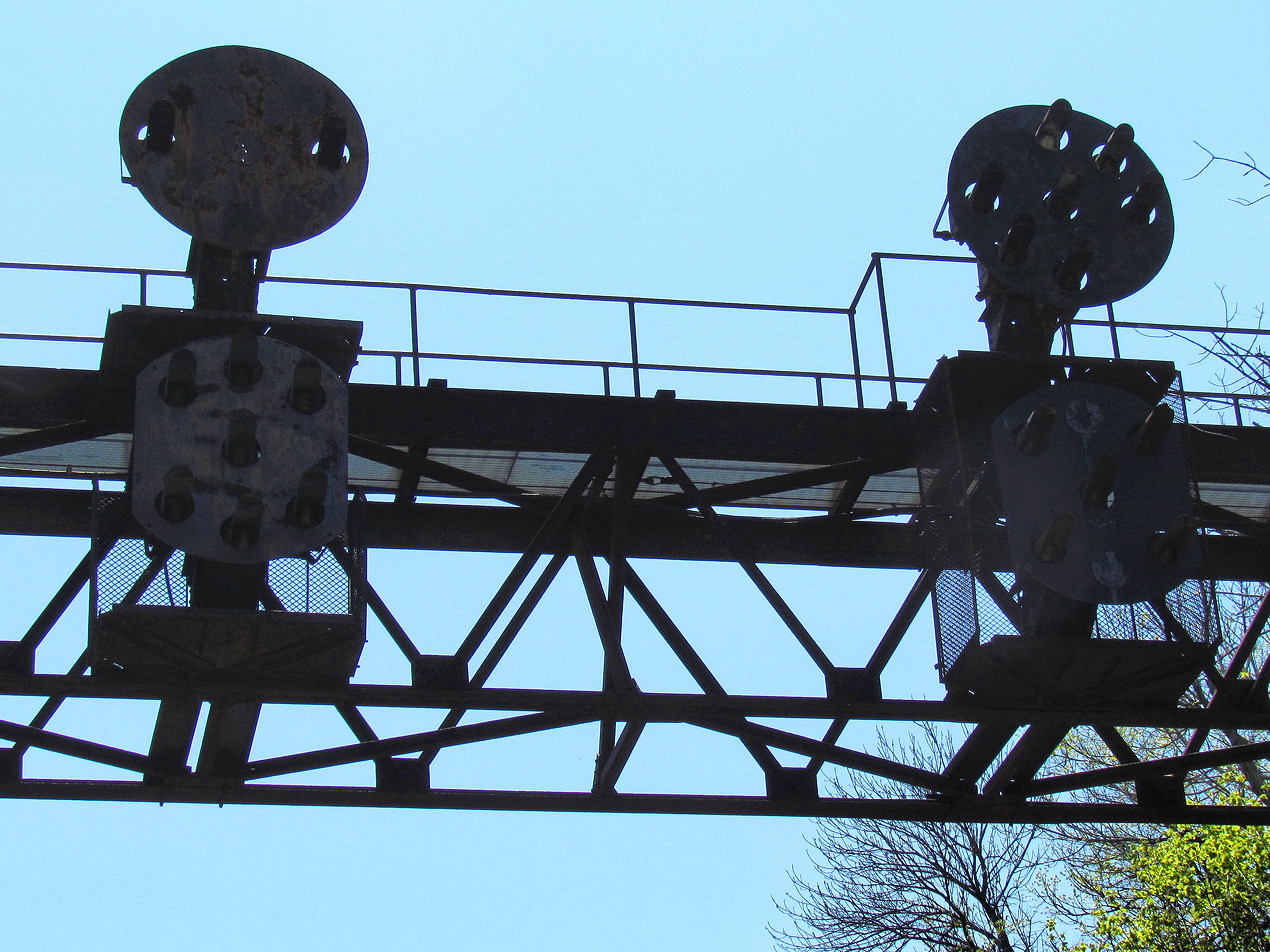
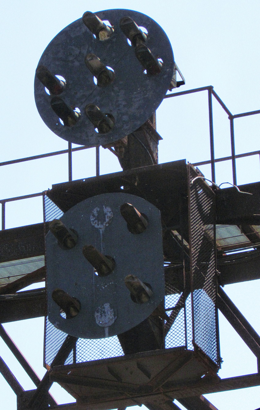
For East (South) bound train WAGO presented a crossover from track two to 2, an interlocked lead to the Brunner Island Power Station and a connection to the Northern Central, now known as the York Secondary. Both the power station and York Secondary tracks were non-signaled and would normally result in Restricting indications. As you can make out on this backlit photo of the eastbound signal bridge the Track 1 "2E" signal is equipped to display a Slow Approach indication as well as restricting. As the interlocking is quite long this was most likley used with an "End of Block" sign when entering the York Secondary.
The Track 2 "4E" signal likely displayed Slow Approach as well, but this distinction was obscured by the additional ability to display Medium Clear and Medium Approach indications for wrong-railing trains crossing over to the "right" direction track. If you are a bit confused here since I already said that WAGO only contained a single facing point crossover you would be correct. WAGO was originally built with a full set of crossovers and later had one removed due to infrequent use. The full lower head on the 4E signal is an artifact of this older configuration.
The old ABS relay cabinet is still in place at the west end signal bridge and still includes a few old signal transformers.
The only remaining crossover at WAGO, #1 switch, appears to have recently undergone some basic upgrades including roller mounted blades and additional electric point heating which includes loop heating elements under the points in addition to longitudinal elements on the rails.
The WAGO relay hut is again typical of Conrail practice being constructed of Corten "protective rust" steel and featuring a milepost number on the blue station sign.
For a more detailed view of WAGO interlocking here is an interlocking chart dating from 1997. There are a number of differences between this chart, the 1998 timetable and the facts on the ground in 2012 and I will get into them as we move through the interlocking. All of the differences are of the "stuff being removed" variety" so the chart has everything that was ever part of the plant.
WAGO interlocking was typical for 1980's Conrail interlockings, making use of existing signaling arrangements as much as possible. In this case the new interlocking was situated at NCRR milepost 67 ABS signaling location south of CLY which allowed reuse of the old PRR signal bridge. Like the other 4-track ABS signal bridges on the 2+2 section this one was elevated on risers (note the old milepost) to clear the overhead catenary when they were installed in the late 1930's and due to the NS re-signaling this is probably the only surviving bridge of this type. Note the disused mounting for the westbound Enola Branch ABS signal at the right of the gantry.
For East (South) bound train WAGO presented a crossover from track two to 2, an interlocked lead to the Brunner Island Power Station and a connection to the Northern Central, now known as the York Secondary. Both the power station and York Secondary tracks were non-signaled and would normally result in Restricting indications. As you can make out on this backlit photo of the eastbound signal bridge the Track 1 "2E" signal is equipped to display a Slow Approach indication as well as restricting. As the interlocking is quite long this was most likley used with an "End of Block" sign when entering the York Secondary.
The Track 2 "4E" signal likely displayed Slow Approach as well, but this distinction was obscured by the additional ability to display Medium Clear and Medium Approach indications for wrong-railing trains crossing over to the "right" direction track. If you are a bit confused here since I already said that WAGO only contained a single facing point crossover you would be correct. WAGO was originally built with a full set of crossovers and later had one removed due to infrequent use. The full lower head on the 4E signal is an artifact of this older configuration.
The old ABS relay cabinet is still in place at the west end signal bridge and still includes a few old signal transformers.
The only remaining crossover at WAGO, #1 switch, appears to have recently undergone some basic upgrades including roller mounted blades and additional electric point heating which includes loop heating elements under the points in addition to longitudinal elements on the rails.
The WAGO relay hut is again typical of Conrail practice being constructed of Corten "protective rust" steel and featuring a milepost number on the blue station sign.
Tuesday, December 17, 2013
DIY Interlocking Machine
I tend to prefer my interlocking towers and interlocking machines "in the wild" that means in service on a real railroad and not "in a zoo" (tourist line) or stuffed (in a museum). Now while something like HARRIS tower and its PLC controlled Model 14 or SoNoToMo and its interactive lever frame are great fun in some way it would have been better had they still been in service, invulnerable to Chinese cyber attack. However today I have discovered an interesting example of an interlocking machine that was neither caught for a Zoo or stuffed for a museum. This one was hand built from scratch for a model railroad and while I don't think it would pass muster at GRS it is certainly better than what most people use on their layouts.
Yup, you are seeing that correctly. This person has built a replica GRS interlocking machine entirely out of wood, from scratch. The best part is that it is being wired up to run the largest New York City Subway model layout in North Dakota. I'm actually nt exactly what if any interlocking logic it uses, but there are a while mess of relays involved so its not completely braindead.
I have to give major props to the wiring job as well.
The builder would have actually prefered a US&S machine (and you can see some of the design elements), but the pistol grips were easier to implement and also control the model train stuff. Still, I'm not complaining.
Yup, you are seeing that correctly. This person has built a replica GRS interlocking machine entirely out of wood, from scratch. The best part is that it is being wired up to run the largest New York City Subway model layout in North Dakota. I'm actually nt exactly what if any interlocking logic it uses, but there are a while mess of relays involved so its not completely braindead.
I have to give major props to the wiring job as well.
The builder would have actually prefered a US&S machine (and you can see some of the design elements), but the pistol grips were easier to implement and also control the model train stuff. Still, I'm not complaining.
Subscribe to:
Posts (Atom)