The following track diagram will apply to this part.

If you forgot all of the photos can be seen here.
The summit of the Alleghenies, like most mountain railroad summits, features a complex of tracks that enables the use of helpers to be cut off and return to base and also accommodate any reductions in main tracks due to tunnels and junctions of alternate / low grade routes. The Gallitzin Summit is not different and at one point featured all of those in a giant interlocking complex known as BN-SF-AR-UN, seen here in this 1948 chart. After a signaling consolidation project during World War 2, the entire complex was controlled from a pair of US&S Model 14 interlocking machines in a new all brick tower overlooking AR interlocking overlooking tracks 1 and 2 with a logically seperate yet direct wire controlled UN interlocking on tracks 3 and 4. East of AR and UN was the previously mentioned SF interlocking where the Muleshoe Curve route diverge and before that was BF that provided a trailing point pre-processing ladder.
Today only AR and UN remain as active interlockings and the tower was closed in 1994. Today CP-AR serves as the eastern end of two sidings off track 1 that run between there and CP-MO. CP-UN acts as a crossover between tracks 2 and 3. Finally, between AR and UN runs a loop track that helper sets (or excursion trains) can use to turn back to Altoona after helping a westbound train over the grade. CP-UN used to have a 3-track PRR signal bridge for westbound movements, but around 2009 it was replaced by a color light cantilever due to structural issues. We can see it here with the 12W and 14W signals.

#15 switch crossover with pneumatic switch machines.

The slow speed loop track splits off between the two crossovers on the #11 switch.

The relay hut is located in the crook of the loop track, adjacent to the #11 crossover.

The restricting-only 14E reverse direction dwarf follows immediately on the Rule 251 West track #3.

Around a bend sits the 12E-1 signal sitting all alone on a 2-track PRR signal gantry. The lower head only offers a Restricting indication as the only routes available are straight ahead or against the flow of traffic on track #3. Back in the day this used to support two semi-automatic exit signals for westbound movements.

After leaving CP-UN we pass under the 2493 automatic, which is for westbound movements on tracks 3 and 4 only. Yes you heard me right, between CP-UN and CP-MO the tracks are renumbered 0 through 4 due to the presence of two siding tracks on the other alignment and thus track 3 becomes 4, 2 becomes 3 and we have a new tracks 2 and 0. This automatic is also distant to CP-MO, mounted on a two track late model gantry and if you look at the bottom | you can see the old mounting bracket for a Limited speed triangle.

You can see the alignment at this location in its near original PRR configuration here.

At this point we reach CP-MO (MOuntain), which was re-signaled in the 1994 clearance project that also closed the tower. Unlike CP-MG, CP-MO got new main signals partly due to the fact that the position lights on the west end were on a low bridge that needed to be removed. The dwarf signals were not replaced. Here we see the westbound cantilever for 3 and 4 track. Off to the right is the extension of the interlocking on track 1 for the track 0 split.

The lever 9 turnout in the foreground used to by rated for Limited speed (40/45ph with), and while the turnout still appears to be a #20 (as it has two A-5 point machines) I am unsure if the home signal and/or the distant give a flashing Limited Clear aspect over it.

CP-MO could have been simplified by moving the start of the new #2 track to the other end of the interlocking past the crossovers, but for whatever reason the layout as a complete 4-track crossover was generally left the same through two rounds of re-configuration. You can see the original PRR diagram here. The only major change besides from the loss of the 4th track to the west was that the 0 track connector was moved to allow access from the ladder track. In modern times I am not sure of the exact function of the two additional sidings between CP-MO and CP-AR, but I assume they are used by trains that need to cut off helpers as tracks 0, 1 and 2 are only used by eastbound movements.

Here are the eastbound mast signals at CP-MO. It was here where the signals used to be mounted on a low bridge that had to be removed in the 1994 clearance project. On track #3 and the siding we can see that the position light dwarf signals have been retained. On the left is the lead track for the Cresson helper base where helper sets are stabled and serviced with fuel and sand. There is another smaller base at Johnstown and also facilities at Altoona, but this is the main facility and where most helper crews sign in. The switch to the spur track after the pot signal on the yard lead is still interlocked and that branch line actually goes to a coal mine about 20 miles to the north. You can see the signal for trains coming off the spur just behind the white posts on the far left. Unlike some countries where trains would need to reverse to use the interlocked switch, coal trains from that branch continue past the helper base and join the main at a hand throw switch What is marked on the MO diagram as the Cresson Branch is also still in use to another coal mine. The Google Map view still shows the tracks in the old configuration where the Cresson Branch used the now removed flyover to 0 track.
At this point I would like to talk about MO tower. There is a lot of good information and pictures on this page from a model manufacturer. MO was fairly standard for PRR Main Line towers in that it was made of wood and dated from about 1890. Older than ALTO it started life with a mechanical frame and was later upgraded with a somewhat non-standard US&S Electro-Pneumatic machine. MO had no "trademark" PRR Bay window, but did have many of the other typical architectural details. Closed in 1994 MO was slated for preservation at a nearby railfan park that included a viewing platform (Cresson PA also has a railfan themed bed and breakfast across from the main line), however when the tower was being moved in 1998 the 108 year old wooden structure literally fell to bits. This is not that surprising considering that the mechanical frame was probably structurally integral and its replacement probably weakened the structure, which was probably built anticipating replacement after a few decades anyway. The same thing happened to the famous Leaning Tower of PD in Patchogue, NY when its lever frame was removed. Some additional inside pics of MO can be found here.
http://www.flickr.com/photos/jonroma/se ... 099457414/
MO tower used to stand just in front of the surviving brick shack that houses the air compressor equipment visible to the right of the tracks.

Finally moving on we reach the 2526 automatic and eastbound distant to CP-MO. This is on a very old model of signal gantry that is probably not long for this world.

There used to be something here at MP 253, but not sure what and when it was removed.

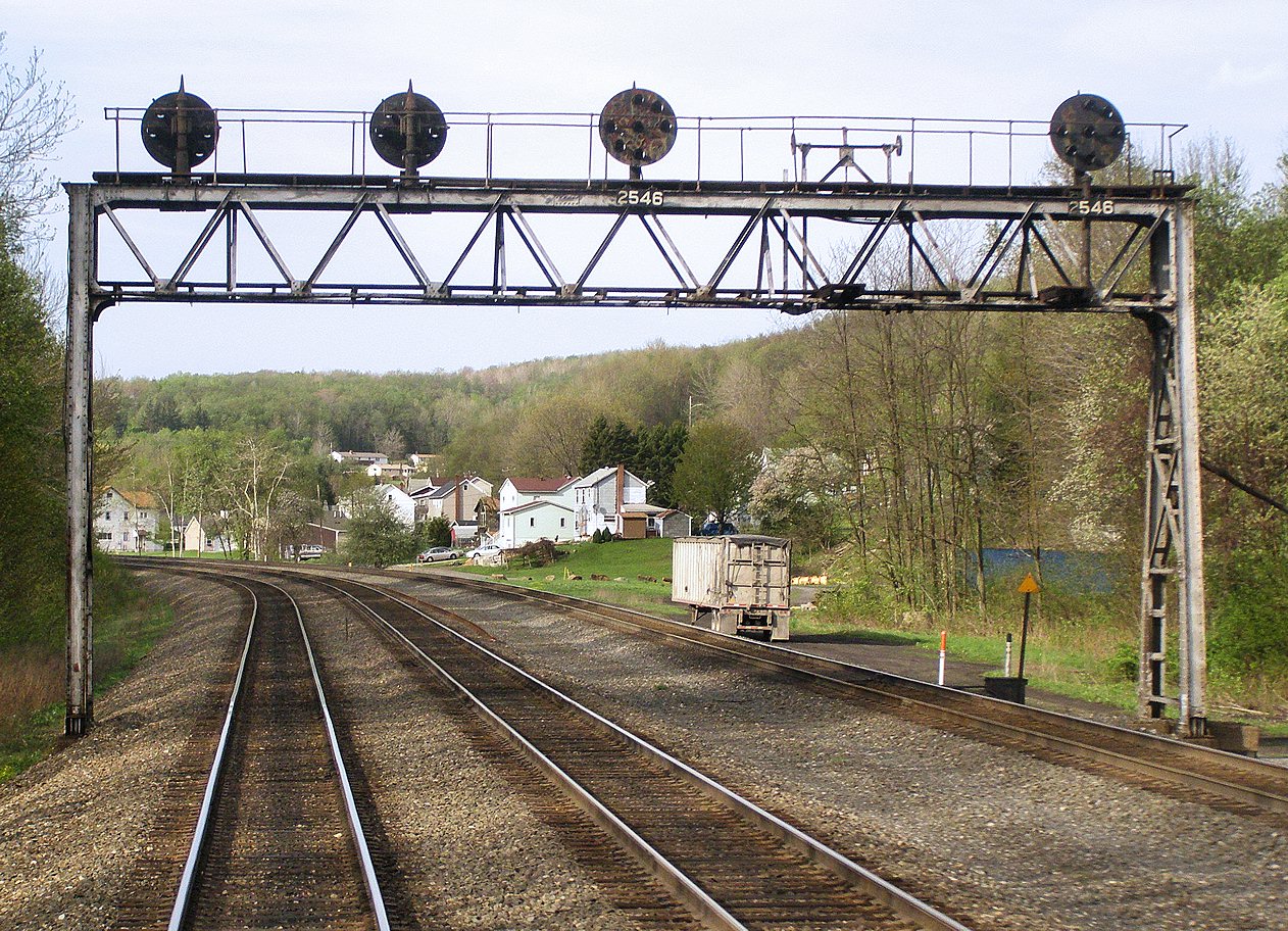
Automatic 2546 on a gantry that was probably painted in the 1980's. After the 80's railroads generally lost interest in painting their classic steel signal bridges.
Automatic 256? for westbound trains only. Another very old lattice gantry with large footings like those seen at MP 253. That shadowy area in the background is the Cassandra Cut, another popular trainspotting location.

A literal signal bridge supports automatic 2572 for eastbound trains. The bridge is open for traffic and one can get close up to the signals. Here a mixed freight train passes that we saw the signal cleared for at CP-MO.

As you can see even short freight trains get helpers, in this case SD40's #3337 and #3338.

The only position light mast signals on this part of the line are the 2588 automatics at Portage. The default direction on track 2 is eastbound as the mast is placed to the right hand side of that track. This is another very popular trainspotting location because of the curve and the easy road access.

Standard type gantry for the 2612 automatic.

It goes without saying that the 2638 automatic has become a popular trainspotting location. This bizarre beastie was the result of a grade crossing elimination project that required a road bridge to be built which in turn would block the line of sight to the 2638 automatic for eastbound trains. The cost effective solution was to raise the eastbound signals up on masts mounted on top of the signal gantry. To ensure workplace safety those little crows nests were constructed along with them. The town has become so enamored with its famous signals (and the trainspotters they bring in) that they erected a preserved position light adjacent to the road bridge that actually cycles through its various aspects.

As you can see the re-mounted signals actually work! BTW, if you noticed these signals are the westbound distants to CP-SO.


The relay hut certainly saved on sign printer's costs.

However the eastbound signals were not so frugal. For some strange reasons both eastbound tracks got a three-headed mast each with all three lamp position occupied. Each of these masts could have been fine with 2 head with a total of 4 lamps. Somebody got a kickback.

This is interesting, a PRR pedestal signal automatic #2656 on the '0' track between CP-SO and CP-W. Don't see many of those. The anti-vandalism screen is also unique.

CP-SO (SOuth Fork) is located right after a sharp curve in the town of South Fork, PA. It was a telegraph operator here that first tried to send warning downstream after the nearby South Fork Dam burst in 1889 in the Johnstown flood disaster. Like CP-MO, CP-SO was completely re-signaled in the 1994 clearance project with the tower being closed and the layout being somewhat rationalized. Position light signals were replaced with 3-track tubular cantilevers and the interlocking became a 3-track crossover with a lead for the siding to CP-W (which itself had hand operated switches to a branch line). Here is the westbound cantilever with the signal heads angled due to the sharp curve. Note the "Begin/End 251" signs. This marks the end of the single direction ABS on the outer tracks.

A wider angle showing the mast signal on the W siding.

My train was crossing over from 3 track to 2 track over the 7 switch. The 9 switch to the siding has a power derail as that track has unprotected yard and branch line switches on it. All points are still air powered.

One day before my Main Line trip in 2008 the closed SO tower burned to the ground. Here we see 6 months later the rubble was still in place.

Here is how SO tower appeared in 2006.

Fortunately many of the internal fittings has been preserved such as the model board as seen at the museum in Altoona. You can see the modified 4-track crossover layout that persisted until 1994. Note the traffic levers 10 and 16 which would co-ordinate with its neighbors (C and MO) to control the bi-directional track 2. The original PRR diagram can be seen here
The interlocking machine was some sort of bizarre chimera that looks to be a mix of a GRS pistol grip and a US&S Style S electro-mechanical machine. I hope it was preserved along with the model board.
http://www.flickr.com/photos/jonroma/se ... 099405506/
Anyway, we continue on, not on track 2.

Here we have the eastbound gantry and even tho #3 track does not have a full speed route the top signal head has all three lamps. Note the Begin/End 261 signs as from now on all three tracks are bi-directional. On the far right we can see the blue Conrail era sign on the relay hut and a newer NS style green sign on a post. I much prefer the Conrail for its size and font. Few other railroads so plainly mark their interlocking names with some like CSX merely stenciling the name on the relay cases in plain black paint.

Between CP-SO and C tower the line was completely re-signaled by Conrail in 1994, although the left the 251-261-251 arrangement in place. As such we are back on the Conrail era numbering scheme as evidenced by the MP 268 automatic. Here we see the Conrail era cantilever, but an NS installed mast signal. That NS mast replaced a single direction Conrail mast in the same location and I think it was just chopped down and placed on the cantilever as the 2683E signal which was not in place on the 1998 diagram. Further evidence for this is the blanking plates on the unused lamps on the 2683E signal are less weathered than the surrounding target. The 2683E cannot display Clear as there are no full speed routes available at CP-SO.

At this point things get a wee bit odd. After miles and miles of 2 mile block intervals ticking by like clockwork we now have a 3-mile block that strikes me as a bit out of place. What makes things especially strange is the presence of at least two places where there are a bunch of signal relay cabinets and a larger general purpose relay cabinet with a big old milepost number on it. It seems like there might be some sort of cab-signal infill blocks, but without any special signals for locomotives with a cab signal failure whatever they put in place would have to be completely backwards compatible. This requires further investigation.

We finally reach the next automatic at MP 271, however this is in service on tracks 2 and 3 only as on track one is CP-AO. My view of CP-AO is blocked by a coal train, but the remains of AO tower (first floor) is still standing as it housed air compressor equipment for the single remaining set of points (since converted to electric operation). AO tower was simplified and remoted to C tower 2 miles to the west. Like SO and AR towers this remote interlocking was direct wired to a separate Model 14 machine in C tower because...yes, the PRR didn't trust that new fangled CTC.
The 271 automatic on tracks 2 and 3 was modified a little bit more transparently for the Rule 261 conversion. The reverse direction signal on track 3 is not like the others. It is a Safetran model that uses its scallop shell modular units normally seen in traffic light signals arranged in a triangular fashion. Note the large open space in the middle of the signal lamps compared to the US&S model that has a single housing for all 3 lamps. The westbound signals with 2 heads are distants to C interlocking.


A little bit further still I was lucky enough to encounter what local railfans refer to as a four banger, ie two helper sets on the back of a heavy coal train in the 10,000 to 12,000 ton range. With the two new SD70M-2's on the front this train is attacking the West Slope with 20,000 hp.

We will close out this part of our journey with CP-C, formerly C(onemaugh) Tower. C tower was closed around 2003 when NS went ahead with the 261 project. C tower is where helpers are attached for eastbound trains and served many of the same functions as ALTO, just without a very large CTC footprint. Here we see the westbound cantilever signal gantry which was installed with the re-signaling replacing a PRR bridge.

While the points remained pneumatic the dwarf signals were replaced with color lights instead of remaining position light as was popular at other re-signaled interlockings such as CP-MO. There are no interlocked pocket tracks between the main tracks with helper sets instead using interlocked pockets to the south of track 1. An original PRR diagram can be found here

The dumpy cinder block C tower was a 1950's replacement for a much more ornate wooden tower that either ran into a train or caught fire. This new tower of course received a pair tried and true US&S Model 14 machines, one for the local plant and one for AO interlocking two miles to the east (CTC bad!). At some point during its life another train derailed into it requiring a bit of a patch job on the east end. Between 1994 and 2003 C was the only other active tower on the non-Amtrak Main Line. Hopefully its air plant and cinder block construction will save it from the wreckers ball.

Some third party interior photos can be seen here.
http://www.flickr.com/photos/jonroma/se ... 101742967/
And the tower in 2004 from the east where you can see the patch job from the derailment damage and the very concise interlocking ID signs.


The eastbound signals were replaced by Conrail sometime around the 1994 clearance project and were retained by NS for the re-signaled interlocking. Again note a CR blue interlocking sign on the new relay hut (probably pulled off the tower) and an NS green sign on a small post. A helper set lays over at the entrance to the interlocking in front of the local crew base.

Next time we start at Johnstown and head westward on to Pittsburgh!
Why was there no high speed route on track 3 at CP- SO? The sharp curve?
ReplyDeleteTracks 1 and 3 are rule 251 so the straight route on Tk 3 would display a Restricting.
DeleteOriginal C tower was destroyed by a derailment
ReplyDelete