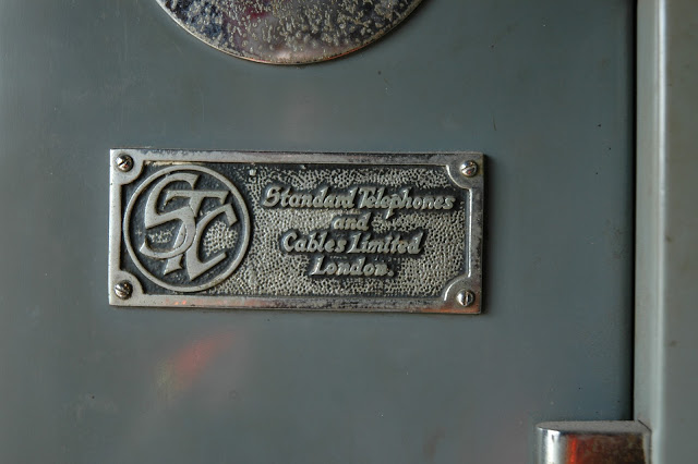
Years ago I wrote up a profile of METRA's GRESHAM JUNCTION tower on the Rock Island division south of Chicago. Not only had GRESHAM JUNCTION managed to stay open into the 21st Century, it was a unique North American example of a sequence switch interlocking. Supplied by the Standard Telephone and Cables Company of London, the interlocking used telecom grade sequence switches to carry out the interlocking functions instead of relays.
In my original post I provide photos of the equipment as well as a general concept of how sequence switches work and some sequence switch interlocking circuit diagrams from the UK, but without time and access to the equipment or someone who was intimately knowledgeable about how it functions, my commentary had to remain at a very high level. Fortunately, the gang from the Connections Museum in Seattle is on the case because sequence switches is pretty much how Bell Number 1 Panel central office machines functioned (again, as opposed to later relay based technologies). I could try to go into things, but fortunately the museum's YouTube channel has video that is specifically about how sequence switches work.
Once you see them in action at the Connections Museum, their function in the photos from GRESHAM JCT will become obvious. Of particular note is the function of the magnetic clutch mechanism that rotates the switch spindle. Perhaps if I stare at things enough I can determine what each sequence switch corresponds to in the interlocking. Is each a complete route? An entrance? An exit? An entrance-exit combination? Let me know in the comments if you figure it out. BTW, if you like this video take some time to watch the rest of the Museum's content. It's top notch and does a superb job of explaining some normally opaque topics in the realm of pre-modern telephone switching technology.


No comments:
Post a Comment