The Reading Darby Creek Drawbridge is located on a bit of industrial track that served industry along the Delaware River between Philadelphia and Chester, PA. Directly paralleled by a competing PRR line, much of the Reading branch and along the the Darby Creek bridge, were abandoned shortly after the formation of Conrail in 1976. 
Nevertheless, movable bridges are substantial pieces of kit with non-trivial removal costs so for the last 45 years the remains of the Reading Darby Creek Bridge have sat in the weeds next to the PRR bridge, permanently open.

It's easy to forget that movable bridges are almost all railroad interlockings, even on otherwise un-signaled territory. Moreover, this means that before CTC the person on hand to work the bridge would also need to work an interlocking machine and both Darby Creek bridges operated in this manner with the tender/operator managing both train movements and marine traffic.

In the case pf the Reading bridge, the interlocking was controlled through a US&S Electro-Mechanical machine with 2 active mechanical levers on a 4 lever frame and 5 active crank style levers on a 7 lever electric frame.

The combination of being manned for bridge openings, no need to associate with CTC territory and flying under the radar in remote locations has allowed for movable bridges to survive as active interlocking towers well beyond even their busiest main line peers. While the PRR bridge ultimately had its interlocking and bridge control hardware replaced in 2005, the Reading bridge, in a strange turn of fortune, unwittingly became a time capsule as Conrail literally turned out the lights on the old bridge in 1976 and walked away leaving the old interlocking cabin and interlocking machine mostly intact.

Placed in service some time around 1923, the Union Switch and Signal Electro + Mechanical interlocking machine used a combination of electric Model 14 style crank levers for electric based components such as the signals, and long mechanical "Armstrong" style levers for the mechanical components such as the bridge locks.

The mechanical levers, 5, 9 and 13, had only 5 and 9 functioning when the diagram was drawn in 1955 to operate the mechanical bridge locks with 5 operating the north lock and 9 the south.

As US&S had taken over the Saxby and Farmer style interlocking machine from the UK, this small frame still used the S&F style rocker action to interface the levers with the logic.

The electric portion of the machine has room for 7 crank style levers with 6 levers originally installed ad one of those being a spare. Three downward oriented levers, 4, 8 and 12, operated a total of 5 smashboard signals, while the upward oriented levers confirmed the position of the bridge locks (#6), worked the master bridge unlock (#10) and served as a spare (#2).

The rear of the machine exposes typical US&S style interlocking
technology including magnetic coils for the quadrant style lever locks
and electric contact spindles to interface the mechanical components
with the various electric circuits.


The mechanical levers connected to a pipeline to actuate the bridge locks. The pipeline made use of the same type of equipment normally associated with land based towers including the dquare rotation shaft. BTW note the surviving Reading style bridge railings.

The #5 mechanical lever worked the north side rail locks, one for each of the four rails. The #9 lever would work the south side with its pipeline able to engage with a traveling pipeline on the movable span that would in turn engage a duplicate set of 4 locks on the south side of the span. In this photo we can see the north side locks operated by the #5 pipes with the #9 pipe proceeding into the engagement mechanism.
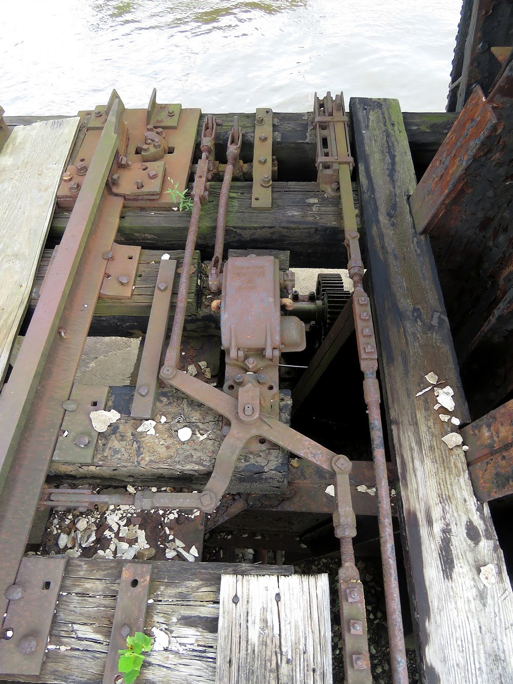
The rail locks ensured proper rail alignment at each of the four rails and also prevented the movable span from moving under a train. Engagement of the locks is determined by 4 position detecting circuit controllers, also one for each rail.

A similar setup can be observed on the south side.

The lever that would mechanically lock the movable span closed was larger than the other two and not considered part of the interlocking machine.

In something for the phone nerds, the Reading Darby Creek bridge really shows its age by way of the emergency contact information that lists a local phone number with 2 letters and 5 numbers!

The adjacent Conrail/PRR bridge was actually fully automated in 2005 with no need for an on-site bridge tender and most bridge ops being controlled by the train crew's radios.

Marine traffic is governed by a railroad style color light dwarf signal displaying *G* Limited Clear when the bridge is open and *R* Restricted Proceed when it is not.


That concludes the tour. Just remember that while vintage towers continue to be demolished, they can still live on in some odd places just waiting to be rediscovered. If you are interested in the full set of photos you can find them here.
No comments:
Post a Comment